All Images : Murray Jones – Transmission Live Line Work Officer at Ergon-Energex
Murray is a specialist trainer responsible for transmission live work audits, re-authorisations and live work method development for live line stick and bare hand crews.
Duties include running training for the transmission and distribution field crews in the areas of High Risk plant up to and including advanced rigging techniques for the electrical transmission industry, with conductor stringing and winching applications for all field crews, along with all applicable rescue procedures and techniques from single person rescue.
275kV V String Insulator Change
Tension Insulator Removal Via 5-1 Tackle Rigged With Samson Rope & Horizontal Ladder
Tension Insulator Change From Horizontal Ladder With 3t Lever Hoist
Changing Bolted Connections From The Horizontal Ladder With D3T90 Structure
Remove Conductors & Change Tower Crossarm. Conductor Left Suspended From Insulators Below Block & Tackle
Concrete Pole Flying Angle Insulator Change. Hook Ladder & Lever Hoist
Lower 275kV Conductor Via Square Rig & 3/1 Tackle Using Samson Rope As A Winch Extension
Changing Bridging Restraint Strings
Horizontal Ladder Training – 6m Side Reach At 40m
Changing Conductor Spacer With Aeropower Helicopters
400kV Live Line Insulator Wash.This is an operational rather than a training shot, but its one of the tasks carried out during Aeropowers live line re-certification training. Insulator washing is performed to remove salt and other pollution deposits from insulator strings which allows them to operate at a greater efficiency. This can be carried out with the line still energised by using “clean” water. Essentially, pure water is not a conductor of electricity.
Subscribe now to our POWER NEWSLETTER– a monthly email circulation packed with news, projects, videos, technical tips, training information, promotions, webinars, career opportunities and white papers.
Includes access to our popular JOINTERS BLOGwith contributions from utility professionals, linesmen and cable jointers working on MV HV EHV cables and overhead lines typically at 11kV, 33kV, 66kV and up to 132kV.
15,000+ Subscribers. ➡
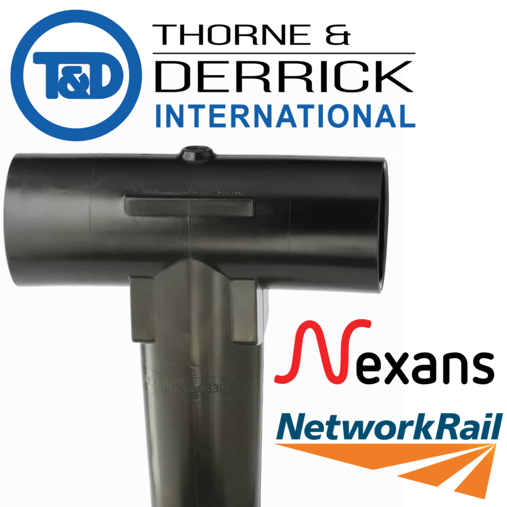
Stokbord Drum Cable Protection for Underground Utility Cables
Stokbord Drum
MV HV Cable Protection for Underground Utility Cables
Centriforce, working through their distributor network including Thorne & Derrick, announce a new cable protection product that can help to improve working safety for utilities applications – known as the Stokbord Drum.
Stokbord Drum cable protection is supplied on a reel allowing minimal effort for the cable cover to be rolled out across expansive areas; a change from the tedious task of laying individual 1m cover sections.
Stokbord Cover is the “go-to” solution with a proven track record for offering heavy duty protection for buried cables and utilities – suitable for major infrastructure projects were speed of installation of operative’s safety is the top prioritises. The drum system also helps to increase safety as it gives a clear visual warning of the presence of underground pipes and medium/high voltage cables.
Stokbord Drum
The new Stokbord Drum system has been developed to provide a mechanical installation option decreasing the need for any manual work. It reduces the manual labour involved and provides a safer environment as workers spends less time in the cable trench. As well as supporting safety on site, the Stokbord Drum also delivers a sustainable solution as it is manufactured from recycled polyethylene waste.
With all the benefits of the traditional Stokbord Covers, and a simple, less manual installation process, the Drum delivers improved safety and value for large scale operations.
Stokbord Drum Features
Time saving installation for cable protection at LV MV HV EHV
Lower risk to operatives and cable installation teams
High impact resistance – cable protection does not shatter on impact
Provides clear visual warning with bright colours and bold warning text
Rot resistant and chemically inert meaning a long service life
Cable covers conform to internationally recognised standards (e.g. BS 2484)
Tried and tested by UK Distribution Network Operators and their contractors
Stokbord Drum offers a faster and safer way of installing Stokbord Cover utility protection. Stokbord Cover is approved and specified by utility companies throughout the world. It offers high visibility and prevents damage to buried HV cables and other utilities including gas, water and telecoms.
Stokbord Sheet is manufactured from post-consumer and post-industrial recycled plastic. This means that there can be some variability in product performance and within finish and colour uniformity. The degree of variability is controlled by our ISO 9001 Quality Assurance scheme.
Please Note: All plastics are susceptible to thermal expansion and contraction with temperature changes.
Manufactured from high impact resistant recyclde polyethylene, Stokbord Cover is able to withstand damage from both hand tools and mechanical plant.
Stokbord Drum was launched at Utility Week Live where Centriforce demonstrated the ease of installation of the new drum system to our clients, alongside our full utility protection range with Tapetile and Locata products.
Stokbord® Drum has since been successfully used on a number of large projects across the UK.
Centriforce Tapetile and Stokbord underground cable protection tiles and covers are the market leading, heavy duty utility protection system for protecting underground cable and pipes – this includes low voltage, medium voltage and high voltage power networks working at 11kV and 33kV.
Stokbord Drum Cable Protection for Underground Utility Cables
THORNE & DERRICK are national distributors of LV, MV & HV Cable Installation, Jointing, Duct Sealing, Substation & Electrical Equipment – we service UK and global businesses involved in cable installations, cable jointing, substation earthing, overhead line and electrical construction at LV, 11kV, 33kV and EHV.
Since 1985, T&D have established an international reputation based on SERVICE | INTEGRITY | TRUST.
Contact us for 3M Electrical, ABB, Alroc, AN Wallis, CATU Electrical, Cembre, Centriforce, CMP, CSD, Elastimold, Ellis Patents, Emtelle, Euromold, Filoform , Furse, Lucy Electric & Zodion, Nexans, Pfisterer, Polypipe, Prysmian, Roxtec, Sicame, WT Henley.
Who better to ask than Chris Barker, a leading UK and International EHV Jointer and owner of CB Jointing Ltd.
Chris informed us, “the perfect cable jointing bay for me would have a concrete float finished floor. Timber sides and horses heads with no acro’s in the way.”
“No other services in the joint bay would be present and no live cables nearby the cable jointing zone. Fault joint bays are a nightmare.”
“Other underground utility services constrict the available working space – this is especially difficult when multiple new cable joints need to be installed.”
Pictured below : Cable Jointing Bay Typical– this cable joint bay has been constructed to accomodate 4off 132kV Pfisterer cable joints.
The joint bay was prepared by the civil engineering contractor – ideally the civils contractor would liase with, and listen to, the site cable jointer to ensure sufficient working room is created when building the joint bay.
Two Pfisterer cable joints need to be installed side by side. And the same at the other end of the bay.
Pictured below : Cable Joint Bay Perfection – note the upright timbers along the joint bay side and perfect clear working area for the cable jointer.
EHV Jointers Glossary
Horse heads – these are 9×3 metre timbers upright in the ground and concrete. Located about 1.9 metres above ground level and then a 9×3 metre across the top of them.
Acro’s – these push the sides of the cable joint bay out to stop the timbers collapsing providing structural stability.
A Battle Between Jointer & Joint Bay….
Chris Barker proves that experience and professionalism can conquer jobsite difficulties. Recall the cramped conditions captured in the top photograph. Now imagine not only the sweat and toil needed to wrestle with the cables and joints but the intelligence and determination to actually accomplish the installation.
Lets watch the magic unfold…….
For Starters – Cable Preparation Perfection
Main Course Served – 1 Joint Down, Just 3 More To Go…..
Back For More – 2nd Joint Down…..
Getting Crowded – not much space left to connect concentric bonds and to fit two PP housings…..
Take A Deep Breath…..
Victory – joints boxed up and ready for backfill. Jointer covered in bruises but triumphant.
Subscribe now to our POWER NEWSLETTER– a monthly email circulation packed with news, projects, videos, technical tips, training information, promotions, webinars, career opportunities and white papers.
Includes access to our popular JOINTERS BLOGwith contributions from utility professionals, linesmen and cable jointers working on MV HV EHV cables and overhead lines typically at 11kV, 33kV, 66kV and up to 132kV.
15,000+ Subscribers. ➡
Competitive Quotations | Large Stocks | Technical Support
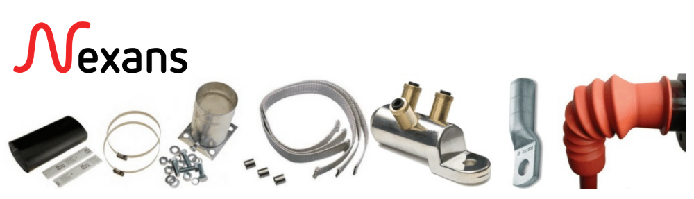
Thorne & Derrick have an International Distribution Agreement with Nexans Power Accessories UK and are their main stockists and suppliers for their range of Heat Shrink Joints & Terminations up to 33kV.
Due to the following Key Points the Nexans brand of Heat Shrink Cable Joints are increasingly preferred and adopted by the renewable energy, rail, power utilities and construction industry.
Key Points
Manufactured by Nexans – “Global Expert in Cables & Cable Systems”
Tested – International Standard IEC60502-4
High Quality Heat Shrink Tubes & Components
No Jointer Retraining Required – Clear Jointing Instructions
Distributed By T&D – Technical Support, Fast Quote & Next-Day Delivery
The Nexans Training centre provides jointer training courses that are specifically tailored to enable upskilling of cable jointers from LV to MV 11kV, 33kV and 66kV.
The Jointer Training courses cover various cable constructions, cable preparation plus the installation of heat shrink / cold shrink push on cable terminations, separable connectors and cable joints.
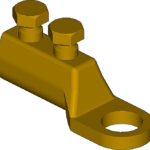
33kV Cable Joint Kits
All 33kV joints are heat shrink type, single phase and include mechanical shearbolt connector
All 11kV joints are heat shrink type, single phase and include mechanical shearbolt connector
All 11kV terminations are heat shrink type, 3 phase and include universal cold-applied boots (FB1), “top-hat” Triplex gland (HSGK2), brass wire screen earth lugs and mechanical shearbolt connectors
Also available – Cold Applied Slip On Joints & Terminations | Euromold Connectors (Screened Separable Connectors)
Cable Terminations & Joints
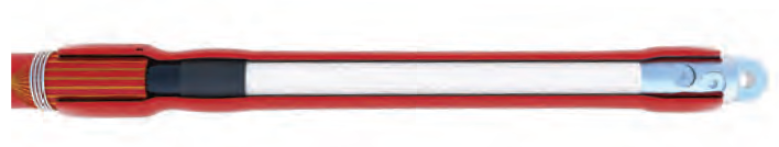
Nexans MONOi heat shrink cable terminations are a one-piece co-extruded anti-track (red) and stress control tube for connection and terminating 11kV BS7870-4-10 Triplex Cables 95-300sqmm into medium voltage electrical equipment.
Easy, quick to install without requirement to retrain Jointers.
Specification & Installation Instructions For Jointers
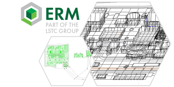
Republished with Permission of Matthew Taylor – Principal Engineer & Managing Director at Earthing Risk Management Ltd
HV System Earthing Design – A Case Study
Project Brief
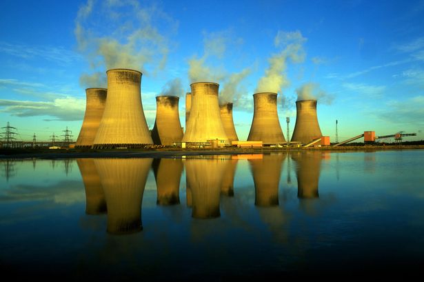
An effective earthing system is vital for large installations such as power stations.
ERM was asked to verify the proposed earthing design against UK standards, including ERM’s previous experience designing the earthing system for the new 400kV connection substation and verifying the designs for the existing 400kV and 275kV substations.
The scale of the site, its varying elevation and the proposed use of a backfill material made this a challenging project.
Challenges
Sheer size; with a site almost a kilometre across, the amount of electrode involved in calculations is taxing for even modern computing with the latest CDEGS software.
Varying surface elevation presented a technical challenge and required the use of specialised functions within CDEGS as well as top-end hardware to process the model and keep calculation times to an acceptable level.
Lateral variation in soil resistivity and significant depths of imported backfill material to be represented in the model. Staged construction of the earthing system in the vicinity of live 400kV and 275kV substations and the provision of 11kV construction supplies present particular safety hazards. ERM was asked to analyse the construction programme and design out any safety hazards associated with the 11kV power network.
Working with multiple companies to progress the project, including international involvement
OUR APPROACH
The size of the power station earthing system, along with the adjacent interconnected sites and requirement to represent a multi layer soil model including backfill representation made the construction and processing of a CDEGS model difficult.
ERM built a bespoke top-end PC to give sufficient processing power to run this model in a timely manner.
Regular liaison with the client throughout the project allowed ERM to understand the breadth of the project including associated areas such as construction techniques and installation methods proposed.
The range of practical and technical experience at ERM allowed us to not only deliver the customer’s requirements but to provide advice value engineering advice, which subsequently provided significant safety improvements and savings in excess of £1M.
PROJECT OUTCOME / DELIVERABLES
The earthing design was approved from a safety viewpoint and significant cost savings were identified during value engineering both for the design itself and for its construction. The saving exceeded £1M.
Safety hazards with 11kV construction supplies were identified and designed out with a pragmatic solution that required little ongoing management.
The finished product was a detailed model with the functionality required to examine, calculate and draw the above conclusions.
Earthing Risk Management Ltd (ERM) was established in 2002 to address the needs of the Electricity Supply Industry to manage safety hazards associated with HV earthing systems.
Since then, the company has grown to be an established, well respected consultancy serving a broad range of clients.
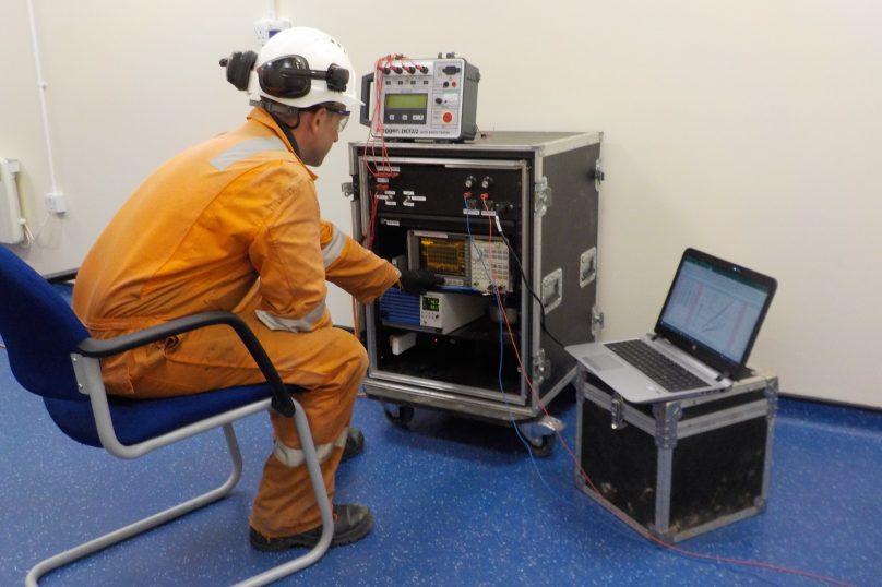
Employing an experienced engineering team as well as full time site testing teams, they are able to manage, assess and evaluate safety hazards associated with all aspects of HV earthing and lightning protection systems.
ERM’s experts from around the world provide their clients with the highest quality services in earthing design and verification, earth testing and measurements, earthing/lightening protection systems commissioning and test pit reconfiguration, pipeline interference studies, high frequency and transient studies, lightening protection design and upgrade, industry training, quantified risk assessment and fault investigation.
Earthing Risk Management has many years of experience in working with many companies throughout the electricity, gas, rail, and renewables industries trust ERM to deliver solutions for critical infrastructure such as National Grid, DNOs, Mitsubishi and Siemens.
➡An onshore substation which was constructed as a part of the new extension for an offshore wind farm project, located in the Irish Sea has a capacity of approximately 750MW.
The power from the offshore wind farm is to be exported by undersea high voltage cables to the 400kV onshore substation where the power is fed into the transmission network.
ERM was asked to test the new, onshore substation earthing system to verify the earthing installation and the CDEGS (Current Distribution, Electromagnetic Interference, Grounding and Soil Structure Analysis) model.
Lightning Risk Assessment
➡ ERM was asked by Uniper Energy to carry out a lightning protection site survey and risk assessment for one of their sites.
Their approach was to attend the site to obtain all relevant information needed to complete the lightning protection risk assessments (LP RA). This information was then passed over to the engineer who could then check that all of the required information was obtained.
This information was entered into specialist software to calculate the lightning risks in accordance with BS EN 62305. Any structures that were above the risk limits were then reassessed with additional lightning protection to reduce the risks to tolerable levels.
The client was provided with a report which detailed the results of these risk assessments and any improvements that they should make to bring the lightning risk levels down.
Accurate lightning risk assessment results were obtained for each of the structures, taking account of existing lightning and surge protection.
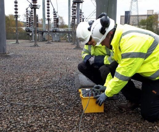
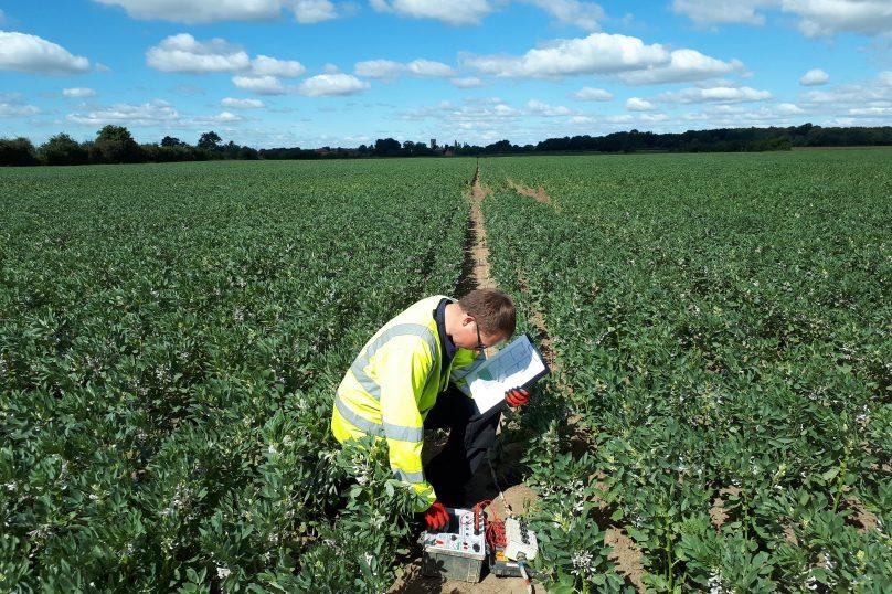
Soil Resistivity Measurement
➡ A new overhead line (OHL) was being built between two EHV substations.
The new planned route was in a difficult location compared to the existing route with Earth Potential Rise (EPR) impacts being likely along the strings. As there is potential for significant impacts ERM were brought in to examine the impact of EPR on towers along the routes.
Their experience and information gathering expertise allowed for the identification of Often Frequented Towers (OFT’s) as points of interest along a significant number of tower spans.
This prioritisation allowed for the planning of Soil Resistivity test routes in proximity to these points of interest only and therefore reduce the number of tests that had to be carried out. This allowed for savings on project costs and time taken to produce results.
The project was delivered to the customer outlining the findings of the study in a timely manner. The report made recommendations to the customer for not only the results but for the possible improvement of this, and any subsequent, studies with regards to the information used and alternative approaches to the study.
Contact ERM
Britannia House, Caerphilly Business Park, Caerphilly, South Wales, CF83 3GG
THORNE & DERRICK are national distributors of LV, MV & HV Cable Installation, Jointing, Duct Sealing, Substation & Electrical Equipment – we service UK and global businesses involved in cable installations, cable jointing, substation earthing, overhead line and electrical construction at LV, 11kV, 33kV and EHV.
Since 1985, T&D have established an international reputation based on SERVICE | INTEGRITY | TRUST.
Contact us for 3M Electrical, ABB, Alroc, AN Wallis, CATU Electrical, Cembre, Centriforce, CMP, CSD, Elastimold, Ellis Patents, Emtelle, Euromold, Filoform , Furse, Lucy Electric & Zodion, Nexans, Pfisterer, Polypipe, Prysmian, Roxtec, Sicame, WT Henley.
INDUSTRIAL LABEL PRINTING SOLUTIONS When clear, durable and professional identification is required across control panels, cable systems, production facilities and industrial installations, print quality, reliability and ease of use are critical. Cembre industrial label printers are designed to support...
HIGH VOLTAGE JUNCTION BOXES & ENCLOSURES When high-voltage power distribution and cable termination are required, safety, enclosure integrity and long-term reliability are critical. HV Junction Boxes and Electrical Enclosures manufactured by Abtech are engineered for the safe distribution, cable termination and protection...


")