

Blog
110kV Cable With Stainless Steel Sheath Plumbed/Wiped To Copper Sheath Cable
May 6th, 2021Image Courtesy of: Andy O’Malley (IBEW 258 EHV Cable Jointer/Splicer).
“This is a stainless steel super sheathed 110kV cable in Brisbane Australia – the high voltage cable had an HDPE graphite coated outer sheath then a stainless steel sheath.”
“A PVC sheath was below the stainless steel then below that a copper sheath. Finally, inside the sheath layers was a 1600sqmm copper conducted XLPE cable.”
“Great project with the Energex boys,” comments Andy.

Further Reading
Confined Spaces Cable Jointing Using 3M Cold Shrink Straight Joint Splice (25kV)
3M Cold Shrink Terminations Connecting Nexans 12kV (MV) Cable Onto Copper Busbar
132kV Termination Using Pfisterer IXOSIL EST SUB Self Supporting Cable Termination
![]()
Jointers blog
Subscribe now to our POWER NEWSLETTER– a monthly email circulation packed with news, projects, videos, technical tips, training information, promotions, webinars, career opportunities and white papers.
Includes access to our popular JOINTERS BLOG with contributions from utility professionals, linesmen and cable jointers working on MV HV EHV cables and overhead lines typically at 11kV, 33kV, 66kV and up to 132kV.
15,000+ Subscribers. ➡ 
25kV Elastimold Tee Connector Terminations Connected To S&C Vista Switchgear
May 6th, 2021Image Courtesy of: Andy O’Malley (IBEW 258 EHV Cable Jointer/Splicer).
Location: Vancouver, Canada.
Jointer: Andy O’Malley
We have the greatest pleasure in showcasing this first example of Andy’s jointing expertise on our Photoblog – terminating medium voltage cable into S&C switchgear using Elastimold Connectors.
We have plenty more Jointers Blogs from Andy, including an image series featuring the pulling, laying and terminating of 138kV Southwire EHV cable using NKT cable terminations.
Jointing is in the O’Malley genes. Andy’s father Patrick inspired him to follow in his footsteps – we hope to soon run some “old-skool” photo’s from the family archive of Patrick’s splicing work.
Whether down the trench or up the pole, Andy is a key member of the Allteck team.
Allteck are international leaders in the design, construction, maintenance and upgrade of overhead and underground high voltage electric power utilities.
S&C Electric Company – Vista® SD Underground Distribution Switchgear
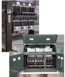
S&C Electric Company offers another choice in metal-enclosed gear.
Economical new Vista SD Underground Distribution Switchgear is the first practical solid-dielectric medium voltage switchgear with a visible open gap and field-replaceable bushings.
The elbow-connected MV switches and fault interrupters are encapsulated in an environmentally friendly solid-dielectric insulating material.
S&C Electric Company Blog – GridTalk
![]()
Jointers blog
Subscribe now to our POWER NEWSLETTER– a monthly email circulation packed with news, projects, videos, technical tips, training information, promotions, webinars, career opportunities and white papers.
Includes access to our popular JOINTERS BLOG with contributions from utility professionals, linesmen and cable jointers working on MV HV EHV cables and overhead lines typically at 11kV, 33kV, 66kV and up to 132kV.
15,000+ Subscribers. ➡
Prysmian 132kV GIS EHV Cable Termination – Connector Welded & Cleaned
May 6th, 2021Images Courtesy: David Young – HV/EHV Cable Jointer at CRS Ltd
Pictured: Prysmian 132kV GIS EHV Cable Termination – Connector Welded & Cleaned

Prysmian 132kV
- 132kV XLPE Cable 630mm² Cu/Pb
- 132kV XLPE Cable 1000mm² Cu/Pb
- Composite Outdoor Cable Terminations
- Single Core Transition Cable Joints
- Three Core Transition Cable Joints
- Link Boxes
- Bonding Lead


Prysmian BICON Cable Joints Cable Glands Cable Cleats Jointing Tools
T&D are distributors for Prysmian Cable Components which includes their range of Bicon cable joints, cable cleats, cable glands and jointer tooling for LV, MV and HV cables.
![]()
Jointers blog
Subscribe now to our POWER NEWSLETTER– a monthly email circulation packed with news, projects, videos, technical tips, training information, promotions, webinars, career opportunities and white papers.
Includes access to our popular JOINTERS BLOG with contributions from utility professionals, linesmen and cable jointers working on MV HV EHV cables and overhead lines typically at 11kV, 33kV, 66kV and up to 132kV.
15,000+ Subscribers. ➡
Long-Term Protection Of Buried 4″ to 8″ Diameter Carbon Steel Pipelines
May 5th, 2021
Project Data
| Location | Sultanate of Oman |
| Client | CC Energy Development S.A.L (CCED) |
| Contractor | Best Oil & Gas Solution LLC and Al Haditha Petroleum Services S.A.O.C. |
| Products | Denso Paste™ , Densyl™ Tape and Denso PVC Self-Adhesive Tape 200™ – both tapes applied with a 55% spiral overlap |
| Date | August 2020 |
PROJECT DETAILS
CC Energy Development S.A.L (CCED) is an independent upstream Oil & Gas Exploration and Production Company which has been operating in Oman since 2007. CCED has had considerable exploration success to ensure long-term sustainability.
Their operating footprint is in Blocks 3 & 4, one of the largest concession areas in the Sultanate of Oman. CCED brings significant exploration, development, and production experience in the oil & gas industry and is an important contributor to the hydrocarbon sector in Oman.
Facts about Block 3:
• The Block is situated in eastern central Oman and comprises an area of 5,911 km2.
• The main producing fields in Block 3 are Farha South and the two recent discoveries of Ulfa and Samha.
Facts about Block 4:
• The Block is situated in eastern central Oman and comprises an area of 23,212 km2.
• The main producing fields in Block 4 are Saiwan and Shahd.
Denso’s high-performance Petrolatum Tape System has been successfully used to protect CCED’s buried Oil & Gas pipelines for approximately 8 plus years.
The system comprises of Denso Paste™, Densyl™ Tape and Denso PVC Self-Adhesive Tape 200™ (yellow). Both tapes are applied with a minimum 55% spiral overlap. In areas of high soil stress, Denso PVC Self-Adhesive Tape 250 or 440 grade (outerwraps) or Denso Glass Outerwrap™ are available subject to the degree of soil stress, and would also be applied with a minimum 55% spiral overlap.
➡ T&D stock and distribute Denso Mastic Duct Seal | Densoseal 16A

ABOUT DENSO
Denso North America Inc. is a subsidiary of Winn & Coales International, a leading manufacturer of anti-corrosion coatings that include Protal liquid epoxies, Denso petrolatum tapes, mastics, primers, bitumen tapes, butyl tapes, hot applied tapes, and a full line of marine pile protection systems. Winn & Coales was originally established as a business in London, England, in 1883, and the first petrolatum tape manufactured in the UK was Denso tape, manufactured under license by Winn & Coales (Denso) Limited.
Denso tape was developed over 80 years ago for the “Long Life Protection” of buried steel pipelines against corrosion. The Denso SeaShield Marine Systems include fiberglass forms, epoxy grouts, underwater epoxies, injectable epoxies, petrolatum tape and wrap systems.
![]()
Further Reading
Sealing & Waterproofing of Cable Ducts Using Densoseal 16A | Thames Water Project
Denso Bore-Wrap | Prevent Coating Damage During Pipeline Installations

Thorne & Derrick are Specialist Distributors to the UK and international Construction industry to provide safe and reliable LV HV Electrical Cable & Power Distribution Systems up to 66kV – we are highly customer responsive and absolutely committed to providing a world-class service.
Contact our UK Power Team for competitive quotations, fast delivery from stock and technical support or training on all LV-HV products.
Key Product Categories: Duct Seals | Cable Cleats | Cable Glands | Electrical Safety | Arc Flash Protection | Cable Jointing Tools | Cable Pulling | Earthing | Feeder Pillars | Cable Joints LV | Joints & Terminations MV HV

Four Ways Of Ensuring Proper Selectivity In MV/HV Electrical Network Protection
May 5th, 2021")
Four ways of ensuring proper selectivity in MV HV electrical network protection (photo credit NSS Ltd)
MV/HV Electrical Network Protection
With Kind Permission of: Edvard Csanyi (Editor-In-Chief & Electrical Engineer at EEP)
Selectivity study of a power system is usually considered as an advanced job for advanced engineers, mostly relay protection engineers.
This article will try to get close to a few important selectivity principles in a simple manner. It’s important to fully understand that protective devices form a logical system in relation to the power system structure and its earthing system.
Protective devices are the brain of a power system based on the principle of selectivity that consists of isolating the part of the network affected by the fault, and only that part, as quickly as possible, while all the other unaffected parts of the network remain energized.
There are various ways of ensuring proper selectivity in electrical network protection..
- Time-graded selectivity (using time),
- Time-graded selectivity with independent time overcurrent protection
- Time-graded selectivity with inverse time overcurrent protection
- Logic selectivity (via information exchange),
- Directional protection selectivity,
- Differential protection selectivity,
1. Time-graded selectivity
Time-graded selectivity consists of setting different time delays for the overcurrent protection devices distributed throughout the network. The closer the protection is to the source, the longer the time delay. See Figure 1.
Thus, in Figure 1, the fault shown is detected by all the protection devices (at A, B, C and D). The time-delayed protection at D closes its contacts more quickly than the one installed at C, which in turn reacts more quickly than the one located at B.

Figure 1 – Time-graded selectivity
Once circuit-breaker D has been tripped and the fault current has been cleared, protection devices A, B and C, through which the current no longer passes, return to standby position.
It takes into account:
- Circuit-breaker breaking time tc
- Time delay tolerances δt
- Upstream protection memory time tm
- Safety margin
∆t must therefore satisfy the relation: ∆t ≥ tc + tm + 2δt + margin (see Figure 2)
For example, for the independent time-phase overcurrent protection devices of the protection relay associated with medium voltage circuit-breakers (see Figure 2):
- tc = 85 ms
- tm = 55 ms | maximum values
- δt = 25 ms

Figure 2 – Time-delay selectivity interval of protection devices A and B
This selectivity system has two advantages:
- It provides its own back-up. Indeed, the protection at C will be activated if the protection at D fails (a healthy part of the installation is cut off);
- It is simple.
However, when there are a large number of cascading relays, the fault clearing time is prohibitive and incompatible with the short-circuit current withstand of equipment, or with outside operating requirements, owing to the fact that the protection furthest upstream has the longest time delay. Thus, the highest fault current is cleared after the longest time delay.
Both types of overcurrent protection (independent and inverse time) can be used.
1.1 Time-graded selectivity with independent time overcurrent protection
The protection time delay is constant and independent of the current. The protection tripping curves are shown in Figure 3.

Figure 3 – Time-graded selectivity with independent time overcurrent protection
The current threshold settings must be such that:
- Iset, A > Iset, B > Iset, C > Iset, D
- Iset, A > Iset, B > Iset, C > Iset, D : current thresholds of protection devices A, B, C and D.
It is estimated that the accuracy of the measuring unit is 10%. Two successive protection devices must therefore comply with the following relation:
- 0.9 × Iset, A > 1.1 × Iset, B or
- Iset, A ≥ 1.22 × Iset, B
In practice, the following values are taken:
- Iset, A ≥ 1.25 × Iset, B
- Iset, B ≥ 1.25 × Iset, C
- Iset, C ≥ 1.25 × Iset, D
1.2 Time-graded selectivity with inverse time overcurrent protection
The greater the current, the shorter the time delay. The protection tripping curves are shown in Figure 4.

Figure 4 – Time-graded selectivity with inverse time overcurrent protection
If the current thresholds are set at a value close to In , both protection against overloads and protection against short circuits are ensured. The following values are, for example, taken:
- Iset, A = 1.2 × InA, Iset, B = 1.2 × InB, Iset, C = 1.2 × InC and Iset, D = 1.2 × InD
- InA, InB, InC, InD : nominal currents at the location points of protection devices A, B, C, and D
To ensure selectivity, the protection devices must satisfy the following two conditions:
Condition #1 – The current threshold must be set to at least 25% above the downstream protection threshold:
- Iset, A ≥ 1.25 × Iset, B
- Iset, B ≥ 1.25 × Iset, C
- Iset, C ≥ 1.25 × Iset, D
Condition #2 – The time delay settings are determined in order to obtain the selectivity intervals ∆t = 0.3 s for the maximum current detected by the downstream protection. For example, for the maximum short circuit at D, the time delay at C must be longer than the time delay at D by a value ∆t .
2. Logic selectivity
As we have just seen, time-graded selectivity has some weaknesses. The logic selectivity system has been designed to eliminate these drawbacks. With this system, perfect selectivity can be obtained when tripping occurs, and, furthermore, the tripping time delay of the circuit-breakers located closest to the source is reduced considerably.
When a fault occurs in a radial network, the fault current flows through the circuit located between the source and the fault point:
- a current flows through the protection devices upstream of the fault;
- a current does not flow through the protection devices downstream of the fault;
- only the first protection directly upstream of the fault must be activated.
A protective device able to send and receive a logic standby order is associated with each circuit-breaker. When a fault current flows through the protection, the latter:
- Sends a logic standby order to the protection directly upstream;
- Causes tripping of the associated circuit-breaker if it has not received a logic standby order from another protection.
Figure 5 gives a simplified description of a radial distribution system.

Figure 5 – Logic selectivity
Operation when a fault occurs at A
A fault current flows through protection devices no. 1, no. 2, no. 3 and no. 4.
Protection no. 1 sends a logic standby order to upstream protection no. 2 and a tripping order to circuit-breaker CB1. Protection no. 2 sends a logic standby order to upstream protection no. 3 and receives the logic standby order from protection no. 1, which locks the tripping order of circuit-breaker CB2.
Protection no. 3 sends a logic standby order to upstream protection no. 4 and receives the logic standby order from protection no. 2, which locks the tripping order of circuit-breaker CB3. Protection no. 4 receives the logic standby order from protection no. 3, which locks the tripping order of circuit-breaker CB4.
Circuit-breaker CB1 clears the fault at A at the end of a time interval: tCB1 = t1 + tc, CB1
- t1 – protection no. 1 time delay
- tc, CB1 – circuit-breaker CB1 breaking time
Operation when a fault occurs at B
- a fault current flows through protection no. 1;
- a fault current flows through protection devices no. 2 and no. 3, which then send a logic standby order upstream;
- only protection no. 2 does not receive a logic standby order and sends a tripping order to circuit-breaker CB2.
Circuit-breaker CB2 clears the fault at B at the end of a time interval: tCB2 = t2 + tc, CB2
- t2 – protection no. 1 time delay
- tc, CB2 – circuit-breaker CB1 breaking time
With the logic selectivity system, the fault clearance time can be reduced and is independent of the number of stages. It is possible to obtain selectivity between an upstream protection with a short time delay and a downstream protection with a long time delay, e.g. by setting a shorter time delay at the source than near the loads.
Note! To ensure safety, the logic standby time is limited, thus allowing an upstream protection to operate as back-up of a faulty downstream protection.
Example: mixed selectivity (logic + time-graded)
Operation of mixed selectivity
")
Figure 6 – Example of mixed selectivity (logic + time-graded)
Logic selectivity is set up between the incoming feeder and the outgoing feeders of each switchboard. The logic link wire costs little since it connects the circuit-breakers or relays to the same switchboard. Between the switchboards, time-graded selectivity is set up, thus avoiding the necessity of installing long logic link wires.
The logic standby time is limited to 200 ms after the time delay of the protection giving the standby order. This allows the protection upstream to operate as back-up for a faulty downstream protection.
Fault at (1)
The protection devices at F, D and B send a logic standby order to protection devices E, C and A, which may be time delayed to 0.1 second, respectively. The circuit-breaker F is tripped after its time delay of 0.1 second. The non-tripping of circuit-breakers D and B is ensured by time-graded selectivity: tD = tF + 0.3 s and tB = tD + 0.3 s.
In the event of failure of the protection at F or the associated circuit-breaker, the protection at E is activated after the logic standby time, i.e. 0.1 + 0.2 = 0.3 seconds. The 0.4 second time-delayed protection at D is also activated (there is no selectivity between E and D in the event of F failing, unless D’s time delay is increased).
Fault at (d)
The protection devices at D and B send a logic standby order to the protection devices at C and A respectively. The circuit-breaker E is tripped after its time delay of 0.1 second.
Fault at (e)
The protection devices at D and B send a logic standby order to the protection devices at C and A respectively. The circuit-breaker at D is tripped after its time delay of 0.4 seconds.
In the event of failure of the protection at D or the associated circuit-breaker, the protection at C is activated after the logic standby time, i.e. 0.4 + 0.2 = 0.6 seconds. Therefore, using mixed selectivity the time delays can be reduced (roughly by a ratio of 2) without going to great expense, since logic link wires need only be installed between circuit-breakers or relays in the same switchboard.
3. Directional selectivity
In a meshed network, in which a fault is fed by both ends, protection that is sensitive to the direction of the fault current flow must be used in order to be able to locate and clear the fault. To do this, directional overcurrent protection devices are used.
We will give an example of directional selectivity for the phase-to-phase faults in a network with two incoming feeders. See Figure 7.
Figure 7 – Directional selectivity for the phase-to-phase faults in a network with two parallel incoming feeders
Circuit-breakers CB1 and CB2 are fitted with directional overcurrent protection devices, whereas CB3 and CB4 are fitted with phase overcurrent protection devices.
For a fault at A:
- The short-circuit currents Isc1 and Isc2 are established simultaneously;
- The directional protection at CB2 is not activated because a current circulating
in the opposite direction to its protection detection flows through it; - The directional protection at CB1 is activated because a current circulating in the same direction as its protection detection flows through it. This causes the circuit-breaker CB1 to be tripped and the current Isc2 is interrupted. An inter-tripping system causes CB3 to open and the current Isc1 is interrupted;
- The protection at CB4 is no longer activated.
4. Selectivity by differential protection
This type of protection compares the currents at the ends of the monitored network section (see Figure 8). Any difference between these currents indicates the presence of a fault. The protection reacts only to faults inside the monitored zone and is insensitive to any external fault. It is thus self-selective.
Figure 8 – Selectivity by differential protection
The equipment protected may be:
- a motor;
- a generator;
- a busbar;
- a cable or line;
- a transformer.
This type of protection has the following characteristics:
- It can detect fault currents lower than the nominal current;
- The time delay may be short, if not zero, since the selectivity is based on the detection and not on the time delay.

Follow EEP – Electrical Engineering Portal
Edvard Csanyi

Electrical engineer, programmer and founder of EEP. Highly specialized for design of LV/MV switchgears and LV high power busbar trunking (<6300A) in power substations, commercial buildings and industry facilities. Professional in AutoCAD programming.
Follow Edvard on LinkedIn here
THORNE & DERRICK
Thorne & Derrick are national distributors of LV, MV & HV Cable Installation, Jointing, Substation & Electrical Equipment – servicing businesses involved in cabling, jointing, substation, earthing, overhead line and electrical construction at LV, 11kV, 33kV, 66kV and EHV. Supplying a complete range of power cable accessories to support the installation and maintenance of low/medium and high voltage power systems:
- Slip-on Cable Terminations
- Cold-shrink Cable Terminations
- Heat-shrink Cable Terminations
- Cable Joints – Heat & Cold-shrink
- Separable Connectors (Euromold)
- Surge Arresters & Switchgear/Transformer Bushings
Key Product Categories: Duct Seals | Cable Cleats | Cable Glands | Electrical Safety | Arc Flash Protection | Cable Jointing Tools | Cable Pulling | Earthing | Feeder Pillars | Cable Joints LV | Joints & Terminations MV HV

