Blog
Pushing & Pulling Loads – RAPP Tools
December 6th, 2022
uploaded by Chris Dodds | Sales & Marketing Manage at Thorne & Derrick
All Content is Copyright of HSE & Original Information is here.
The HSE aims to reduce work-related death, injury and ill health.
Pushing and pulling of loads is a way to reduce or avoid manual lifting and carrying. Putting the load on a trolley and pushing it is one way of avoiding carrying.
So, when people push and pull instead of lifting and carrying, less effort is required, but there may still be a risk of musculoskeletal disorders (MSDs), which you need to assess and eliminate or reduce.
Although you may think that the Manual Handling Operations Regulations only apply to the lifting, lowering and carrying of loads, they also apply to pushing and pulling.
This ‘pushing and pulling’ guide should help you comply with the regulations and control the risks to your workers.
A risk assessment tool for pushing and pulling operations (the RAPP tool) is available:
- It is a simple tool designed to help assess the key risks in manual pushing and pulling operations involving whole body effort.
- It is similar to the MAC tool and uses colour-coding and numerical scoring, like the MAC.
- It will help identify high-risk pushing and pulling activities and help you evaluate the effectiveness of any risk-reduction measures.
- You can assess two types of pulling and pushing operations using the RAPP:
- moving loads using wheeled equipment, such as hand trolleys, pump trucks, carts or wheelbarrows;
- moving items without wheels, involving dragging/sliding, churning (pivoting and rolling) and rolling.
- For each type of assessment there is a flow chart, an assessment guide and a score sheet.
NOTE: Since the RAPP tool was launched, our experience, supported by further testing, has indicated that the tool is not sensitive to the level of risk in some tasks (or parts of tasks) involving moving loads with hand pallet trucks or similar, with small wheels.
In these tasks, small irregularities (including debris) and small gradients in the floor surfaces, which would otherwise be assessed as low risk (Good G/0) under the A-7 Floor surface and A-8 Obstacles along the route factors, can have a very significant effect on the manual forces required. In these situations, the RAPP will tend to underestimate the level of risk, although the need for high force should be identified from looking at worker posture in factor A-2 Posture.
Therefore, a full, site-specific, pushing and pulling risk assessment may be preferable when assessing tasks (or parts of tasks) in locations with varying floor and environmental conditions. This is particularly likely for tasks that occur outdoors or can be affected by the weather, such as deliveries or loading/unloading in yards. Worker involvement in the assessment process is important as they have valuable knowledge of the specific risks of the task, particularly, for example, drivers who are experienced in delivery operations.
HSE has produced a pushing and pulling risk assessment checklist and an example checklist to help with your full risk assessments – contact HSE for further information.
Push Pull Tools
The range of Push Pull Tools manufactured by the Hand Safety Tool Company and distributed by Thorne & Derrick provide significant Health & Safety Improvements around site where “pushing and pulling” operations such as handling deliveries or loading/unloading in yards is commonplace. This download produced by the UK HSE enables the Risk Assessment according to Load Weight, Operation Frequency, Push/Pull Distances and other impacting factors – the range of tools to keep hands off loads, enable “hands-free” lifting, mitigate risk of load handing and prevent hand or finger injury are available in the UK from Thorne & Derrick.

ShoveIt Hand Safety Tool | Prevention of Hand & Finger Injury
The ShoveIt Hand Safety Tool is manufactured by Hand Safety Tools and stocked and distributed by Thorne & Derrick.
ShoveIt tools are designed to help users avoid hand injuries while working with suspended loads or manoeuvring objects. The tool ensures correct ergonomic body positioning for safe handling out of the line of fire, while enabling users to guide loads, move and position objects, as well as grab slings and taglines without physically placing hands on the item.
Thorne & Derrick distribute a range of Safety Tools from Hand Safety Tool Company designed to minimise hand injuries by keeping hands out of the line of fire.
Over a quarter of a million people suffer serious hand injuries each year. The Hand Safety Tool Company works hard to help to reverse that trend by creating No Touch Hand Safety Tools that keep hands off and away from potential injury areas. The range of Safety Products are the result of numerous conversations and in-field encounters over the last decade with key Health & Safety Officers and “boots-on-the-ground personnel” to ensure each tool produced does the most important job of all – helps every user to keep their hands.
![]()
High Voltage Cable Accessories 66kV 72.5kV | Nexans Euromold | New Catalogue Download
December 2nd, 2022
Distributed in the UK by Thorne & Derrick International
-
uploaded by Chris Dodds | Sales & Marketing Manager at Thorne & Derrick
Joints Termination Connectors Tools
Nexans Power Accessories is the leading European innovator and manufacturer of Low, Medium & High Voltage Cable Accessories as well as connection technology for energy transmission and distribution networks, including both onshore and offshore renewable projects. The Nexans range of Medium Voltage Power Cable Accessories ranged is stocked and supplied in the UK by Thorne & Derrick, contact us for commercial quotations, specification support, product training or to discuss your requirements.
Power Cable Accessories for High Voltage Power & IAC Cables 66kV 72.5kV
Catalogue Contents | ↓ Catalogue Download ↓
Euromold
R909TB/G – EUROMOLD® Tee connector, Interface F
R909PB/G – EUROMOLD® Coupling connector
900SA-CD – EUROMOLD® Surge arrester, Interface F
R900BE/G – EUROMOLD® Bushing extender, Interface F
R900DR-B/G – EUROMOLD® Dead-end receptacle, Interface F
900GP-SBT – EUROMOLD® Grounding plug, Interface F
Possible arrangements Interface F
R900AR-8 / R900AR-12 – EUROMOLD® Equipment bushing, Interface F
Fixings for equipment bushings
AFN72 – EUROMOLD® Slip-on termination for indoor and outdoor use
AFNS72 – EUROMOLD® Slip-on termination with support
FEV72.5 – Outdoor termination with composite insulator
ESC – EUROMOLD® Premoulded EPDM stress cone
Ready to install, pre-assembled cables
72MSJ – Slip-on single core straight joint
72MSJ-x-SB – Sectionalizing slip-on single core straight joint for cross-bonding application
Slip-on tools
900OJF P1-P1 – Offshore junction frame
900OJF P2-P0 – Offshore junction frame
900OJC P2(3)-P1(2)(SA) – Offshore junction cabinet
➡ See Also | Heat Shrink MONO Terminations MV HV | Heat Shrink JTS Joints MV HV


Specialist Distributors to the UK and international Offshore Wind & Renewable industry to provide safe and reliable LV HV Electrical Cable & Power Distribution Systems up to 66kV – we are highly customer responsive and absolutely committed to providing a world-class service.
Contact our UK Power Team for competitive quotations, fast delivery from stock and technical support or training on all LV-HV Cable Accessories & Electrical Products.
WEBINAR | Glass Fibre Reinforced (GRP/GFRP) Cable Support Systems (CPD APPROVED)
November 23rd, 2022 Cable Support Systems (CPD APPROVED)")
Cable Support Systems
What is GRP?
GRP/GFRP (Glass-fibre reinforced polymer) cable support and trough systems possess unique properties that enable them to resist highly corrosive environments; particularly where conditions indicate that conventional materials may not provide an economic service life. During this brief but comprehensive webinar/online learning; you will be getting to know more about the type of cable support system designs; GRP as a composite material from the sustainability point of view; how to choose the right cable support; advantages of GRP cable support systems; its applications and many more. This course is designed for beginner and intermediate learners.
Thorne & Derrick are a Preferred Distributor & Supplier of MITA brand Cable Support Systems – contact us for scheme design, specification guidance and competitive delivery of product from UK stocks at reduced lead times.


MITA brand is now powered by Wibe Group. MITA have been supporting customers through their technical journey on choosing the correct product, manufactured from GRP, in cable support applications for almost five decades. MITA are now fully separated operationally from Schneider Electric. They now have a stand alone presence in the UK market with their “Made in UK” products which are fully compliant to the related cable management standards. MITA are marker-leaders in the manufacture of CABSYS cable trays and GRP cable ladders
![]()
GRP Cable Support Systems | Features & Benefits
November 23rd, 2022
GRP Cable Support Systems
Thorne & Derrick together with Mita® can offer an extensive range of GRP cable support solutions that are suitable for any kind of application. As a leading manufacturer of corrosion resistant industrial cable support products, Mita® hereby presents all you need to carry and support each and every kind of electric cable, data, instrumentation, computer or power circuit without any doubt.
Their GRP offer includes a complete industrial cable support systems and trough range specifically designed for harsh and corrosive environments. Whether you are specifying a range of equipment for a major project or buying a selection of components for a simple maintenance installation, their range is unequalled.
What is GRP?
GRP is a composite material formed if glass rovings/shavings together with resin fillers and additives. GRP is the abbreviation of Glass Reinforced Polymer, meaning it is a man-made resin based material which makes it a polymer, reinforced with glass. There are also different acronyms used by different manufacturers, such as FRP and GFRP, however, they all refer to the same type of composite.
The mechanical properties of GRP can vary widely depending on the matrix fibre combination, fillers, veils, reinforcement design, and manufacturing methods.
These properties allow an initial comparison of different types of composites as well as providing a benchmark against which to measure the success of the specific recycling process in achieving acceptable material properties.
How is GRP Manufactured?
GRP is manufactured through a process called pultrusion.

Above you see the glass rovings going into the resin bath, then mats are placed on to these to create the profile first and goes into the die which shapes and cures it in the form of a ladder or tray, and at the end of the line it is cut to the required length.
Pultruded Technology is used whenever the benefits of whole life cost are appreciated and although the process was originally developed in the USA around 50 years ago, low levels of technology have traditionally meant high costs and therefore applications suited mainly to the extreme longevity of the material.
Pultruded Composites consist of four or five main elements:
1) Glass rovings (strands) and mats -approx. 50% by weight
2) Resin – usually Polyester
3) Filler – usually Calcium Carbonate
4) UV Veil and UV additives
5) Fire Retardants as required
Pultruded composites remain largely impervious to corrosion regardless of application. The GRP pultrusion process uses a combination of unidirectional and cross strand glass mat which is resin impregnated and pulled through a hot die to produce a very solid, structurally sound profile.
Pultrusion process gives outstanding structural strength when compared to other composite processing techniques.
GRP Cable Support systems
Production Methods
There are 2 common production methods for GRP cable support systems, which are moulding and lamination (though pultrusion) and do not produce the same results.
Compression Moulding:
Light / Medium Duty
1.Enough structural strength for light and medium duty applications (Low/medium load carrying )
2.Glass content is around 20-25%
3.High filler content
4.Orthothalic resin or Isopthalic resin which might end up having a low fire retardancy
5.Good for indoor applications, its manufacturing results in nice bends and better shape
Lamination through Pultrusion:
Heavy duty
1.High structural strength for heavy duty applications (high load carrying)2.Glass content is around 40-55%
3.Low filler content
4.Isopthalic polyester resin which has a good corrosion/fire performance, and Acrylic resin resulting in better corrosion, fire performance and low smoke/fumes
5.Good for indoor and outdoor applications thanks to the UV surface veil applied during the lamination
The main 2 methods that we come across in GRP cable support manufacturing is pultrusion and moulded manufacturing.
Cable Trough Resin Types
MITA offers 4 main resin types to accommodate the requirements of various industrial applications which can be in chemically aggressive, demanding heated environments.
 |
POLYESTER Type 2 | Referencing Convention: Ending with PY2 This type of polyester is for general applications, is resistant to corrosion suitable in industries using heavy chemical and caustic materials, and resistant to UV light by nature. |
| POLYESTER Type 1 | Referencing Convention: Ending with PY1 This type of polyester has better fire retardance which makes it suitable for railway, trackside and any other application requiring UL94 compliance and 5VA classification. |
|
| POLYESTER Type 1 Carbon Loaded | Referencing Convention: Ending with PY1C This type of polyester has anti-static properties as it contains carbon powder. It, therefore, requires grounding. It is for on-shore and off-shore oil and gas applications which are classified as explosive environment. |
|
| MODIFIED ACRYLIC | Referencing Convention: Ending with MX This type of polyester has anti-static properties as it contains carbon powder. It, therefore, requires grounding. It is for on-shore and off-shore oil and gas applications which are classified as explosive environment. |
Cable Trough Approvals
| Materials | Standards |
| PY2 | BS 476 Part 7 |
| BS EN 60695-2-12:2001 | |
| PY1 | UL 94 – V0 |
| UL 94 – 5VA | |
| BS EN 60695-2-12:2001 | |
| PY1C | BS476 Part 7 |
| UL94 – V0 | |
| UL94 – 5VA | |
| NES713 | |
| BS60079-0 | |
| BS EN 60695-2-12:2001 | |
| MX | BS 476 Part 7 |
| BS 476 Part 6 | |
| NES 713 | |
| BS 6853 – D8.3 | |
| BS 6853 –D8.4 Cat 1B | |
| BS 6853 – Annex B2 | |
| BS EN ISO 4589-2 | |
| BS EN iSO 4589-3 | |
| UL 94 V0 | |
| UL 94 5VA | |
| BS EN ISO 4589-2 | |
| BS EN ISO 4589-3 | |
| BS EN 60695-2-12:2001 |

| References | |
| Wibe full reference | Wibe quick reference |
| Polyester Class 2 | PY2 |
| Polyester Class 1 | PY1 |
| Polyester Class 1 Anti Static | PY1C |
| Acrylic Class 0+ | MX |
GRP Cable Support Solutions
Features & Benefits
| Features | Benefits |
| Light weight Density and weight are significantly lower than steel (70% lighter than steel) with reduced handling requirements. Lightweight in design. |
Health & safety Reduced risk of staff injuries due to its lightweight, easy to cut, no hot works requirement, no deburring and no sharp edges. |
| Compression strength Despite its lower weight, tension, flexure and compression strength of GRP is almost 20 times that of steel with much greater safety factors. It does not deform permanently under high loads. Slow heat transfer allows for even stronger mechanical resistance. |
Low installation & transport costs Typically between 30-40% less than steels with easier cutting, drilling and no deburring, painting or earthing. Transportation costs are more economical and the ease of installation ensures that GRP is the more cost effective solution. |
| Slow heat transfer & resistant to electromagnetic pulses It is effective at temperatures between -140oC to +120oC. Resistant to electromagnetic pulses and transfers heat more slowly than steel. Composite materials are excellent insulators having a thermal conductivity 1/60 of a steel product, and do not require earthing. |
Long life & low maintenance Composites are corrosion resistant and maintenance free. Our GRP products are designed and manufactured to withstand a majority of chemicals & extreme weather – without requiring further maintenance. No rusting, even when exposed to salt spray, H25, acid build up from exhaust gases or brake dust. |
| Zero halogen, UV & corrosion resistance GRP cable support solution is resistant to UV and corrosion, and is zero halogen. It is also available in low smoke classified material. |
Fire performance GRP is zero halogen. It has low heat and electrical conductivity, and is available in self extinguishing and low smoke material. |
| Offer & design Available in 3m and 6m lengths. Full range of pre-manufactured bends, jointing bays and transitions available for fast installation. Dedicated design facility to support bespoke solutions. |
Installations & modifications are simpler Mita GRP solutions offer a far easier installation, without the need for painting, earth bonding or special tools. Supplying 6m or 3m lengths reduces amount of couplers required. |
MITA, Schneider Electric + Wibe Group
In 1988, Mita Holdings Ltd was born. In a short while, the company became a leading manufacturer of corrosion resistant industrial cable support products in the UK. In 2005, the company was acquired by Schneider Electric under the name of Mita (UK) Ltd. Mita name continued as a range name under the Schneider Electric brand. Finally, in 2021 the cable support division is acquired by the Swedish group, Storskogen, and is reborn as a stand alone company, Wibe Group.
MitaR is back as a leading brand in GRP cable support solutions. MITA brand is now powered by Wibe Group.
MITA have been supporting customers through their technical journey on choosing the correct product, manufactured from GRP, in cable support applications for almost five decades. MITA are now fully separated operationally from Schneider Electric. They now have a stand alone presence in the UK market with their “Made in UK” products which are fully compliant to the related cable management standards.
MITA are marker-leaders in the manufacture of GRP non-metallic troughing, GRP cable ladders, CABSYS cable trays, ducts, cable support channels and Fibastrut as the brand continues to lead the industry towards a sustainable future for a wide range of low (LV), medium (MV) and high voltage (HV) cable installation applications.
RAIL CABLE ACCESSORIES, ELECTRIFICATION

& INSTALLATION EQUIPMENT
Thorne & Derrick supply an extensive range of 400V-33kV Rail Cable Accessories & Power Distribution Systems including feeder pillars to contractors undertaking Low Voltage Power Distribution, HV Electrification & Substations, DC Traction & Networks, OLE and Track Feeder Cable Renewals – a complete range of Network Rail PADS approved track terminations, cable joints, cable repair and connection products up to 25kV, including 3M Cold Shrink, Pfisterer CONNEX and Nexans Euromold products.
Full range of Cable Pulling Equipment & Products to ensure safe and efficient of rail cables in to cable ducts and containment infrastructure including cable troughs.

Cable Cleats | Cable Hangers | Cable Joints | Cable Glands | Cable Lugs | Cable Transits | Arc Flash Clothing
Earthing System Testing | Are We Really Testing R, Z or Something Else?
November 15th, 2022![]()
Earthing System Testing
-
Special thanks to Stephen Palmer from Safearth for kind permission to republish this article
In theory, earthing system testing is very simple, but in practice somewhat more complicated. Recently our development engineers Matthew Lee and Steven Preedy asked the question…Are we really testing R, Z or something else?
The authors have investigated and tested a range of scenarios and instruments and sought to be definitive. This article presents their methods, results, and conclusions.
In theory, earthing system testing is very simple. One simply applies a voltage between the system under test and a remote earth electrode, measure the current, measure the voltage ‘across’ the system under test, and divide it by the current.
In practice earthing system testing is somewhat more complicated. Questions often arise regarding the practicalities of testing, including:
- How do you establish a suitable remote earth?
- What type of voltage do you apply?
- How much current flow do you need?
- Where & how specifically do you measure the voltage?
- How do you measure both reliably?
- How do you detect and reject (or correct for) electrical noise, both AC & DC?
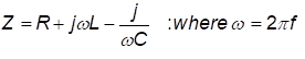
These are all important questions, and whilst many have reasonable answers, one question remains in dispute: If you test with an applied voltage that has both DC & AC characteristics, do you measure a resistance or an impedance?
The IEEE committee revising Std 81, amongst others, have wrestled with this question, and currently, there is no consensus. To answer the question “Are we really testing R, Z or something else?” the authors have investigated and tested a range of scenarios and instruments and sought to be definitive. This article presents their methods, results, and conclusions.

Safearth consultants in the field performing soil resistivity testing
Why are we asking this question and what are we testing?
For an earthing system to be effective, its performance needs to be adequate for the power system attached to it and all the factors that affect its performance need to be considered. The performance of the earthing system is entirely dependent of the ground in which it is placed.
The soil composition, existing infrastructure and mineral/moisture content all affect the apparent resistivity of the soil and thereby the performance of the earthing system. To assess the performance of an earthing system requires tests of parameters associated with or affecting that performance, including soil resistivity, EPR, resistance of earth grid, loop impedance, and continuity.
How Are We Testing?
To measure each of the aforementioned parameters current must be injected into the earthing system and/or the surrounding soil and the response measured. The injected current can be either a ‘Switched DC’ or an ‘AC current’ injection.
In both methods, the current is known, and voltage is measured. The question we are investigating here is “for a switched DC injection how should the measured voltage be interpreted?”
How do switched DC instruments work?
Switched DC instruments inject a known current in the form of a switched current square wave into the system. The voltage measurement is conducted at a specific part of the injected waveform, some in the middle and some at the end of the waveform.
Measurements are taken at these points to remove the effect of test lead coupling. With a known current and a measured voltage, ohms law can be applied – (R=V/I) to deduce the measured resistance.
What Happens When It Gets Complex?
Reactive elements in the system introduce complexity to an earthing system’s response. When measuring a complex system, the presence of reactive elements can affect the measured result. These reactive elements come from auxiliary paths such as overhead earth wires, buried conductors and cable screens.

Figure 1 Resistance Measurement of Complex Earthing System
How we showed the measurement can include errors
Using two switched DC instruments, we set up an equivalent circuit that would allow us to change real and reactive components. From this we could simulate how the measurement waveforms become distorted as the ratio of L to R increases and what the resistance tester records as the apparent resistance.
The setup was measured with zero inductance initially to establish a control value. All other measurements with inductance were compared to the control value.
What happens when we have reactive elements?
Based on one theory the behaviour of reactive elements is just …
The reality is that high inductance reacts to the injected switched DC current such that the resulting voltage waveforms become distorted, as shown in Fig 3. The distortion in the measured voltage waveforms create error within the measured resistance.
The result is that the magnitude of the measurement is larger than the resistive component of the circuit and is not indicative of the system under test. If the reactive element is small in relation to the real resistance, there exists a plateau near the falling edge of the received signal. This plateau is the real magnitude and contains little to no error being uninfluenced by the reactive element. By using the plateau of the signal, the measurement can be effectively used to calculate the real resistive element.

Figure 3 Measured voltage waveforms in high inductance circuits
How does impedance affect the results?
What we found was that the effects of inductance on measurement accuracy and reliability are dependent on the ratio of R to L, with the following features:
- Large R values negate low L values;
- Large L values dominate low R values;
- The L/R ratio does not imply the associated error;
- The error becomes significant when the millihenry range of inductance is reached; and
- The lower the frequency the more time for reactive elements to dissipate, allowing more time for a plateau to be reached.
Are we measuring an impedance with switched DC?
The short answer is no. Switched DC current injection measures the voltage at a certain point of the waveform and applies Ohm’s Law (R=V/I). It cannot measure a phase angle and thus cannot get a phase shift to deduce impedance.
The long answer is, it’s complicated. Due to the truncated measurement window technique used specifically by these testers, quantifying the amount of reactive information captured in that sample window is not trivial. In addition to this, the result is not a linear increase in error for a linear increase in inductance.
Does It Matter?
Typically, switched DC measuring instruments are reliable for individual electrodes, groups of electrodes and small to medium sized grids with no or minimal interconnecting paths. When testing on large grids or grids with multiple auxiliary paths, the effect of reactive elements can be observed by changing the injected frequency and noting that the recorded resistance changes with frequency.

Safearth engineers in the field performing soil resistivity testing
We ask again…. Are we really testing R, Z or something else?
These instruments are suitable for testing a resistance until they cross an implicit R/L ratio threshold. Past this threshold it appears that the inductive (L) component affects the measurement sufficiently such that substantial error can be observed. This measurement is relative to the circuit under test, but the reactive element cannot be deduced.
Through this investigation, it was found that 3 & 4 terminal switched-DC testers are always attempting to measure a resistance. When significant reactive elements are introduced into the circuit under test, the instrument ends up reading something else as it is trying to calculate resistance despite the measured waveform being distorted by the presence of the reactive elements. This implies that it is not an impedance being measured, the value that is calculated is only relevant to that specific circuit.
A way to check if there are reactive elements in the circuit is to change the frequency of the square wave. If the value doesn’t change, then it is dominantly resistive, and the measured estimate is valid. However, if the measured value changes significantly, there is enough of a reactive element in the circuit under test to affect the result and it must be considered an invalid measurement.
This article comes from the perspective of Safearth development engineers Matthew Lee and Steven Preedy who research, design, develop and manufacture our suite of Safearth earthing system test instruments. Their consultants regularly use our earthing testing equipment in the field in Australia and overseas. Original article can be found here – https://www.safearth.com/are-we-really-testing-r-z-or-something-else/
About Safearth
![]()
Safearth is a specialist electrical engineering group providing world-recognised expertise in safe power earthing systems.
Safearth delivers comprehensive earthing solutions and management to safeguard people and infrastructure from electrical faults and lightning. Since being established more than 30 years ago, we’ve designed and tested thousands of earthing systems for high voltage installations, for power utilities, mines, oil & gas sites, and other industries.
![]()
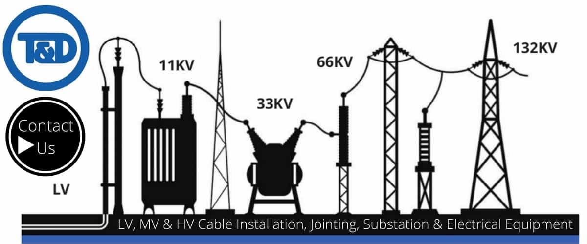
THORNE & DERRICK are national distributors of LV, MV & HV Cable Installation, Jointing, Duct Sealing, Substation & Electrical Equipment – we service UK and global businesses involved in cable installations, cable jointing, substation earthing, overhead line and electrical construction at LV, 11kV, 33kV and EHV.
Since 1985, T&D have established an international reputation based on SERVICE | INTEGRITY | TRUST.
Contact us for 3M Electrical, ABB, Alroc, AN Wallis, CATU Electrical, Cembre, Centriforce, CMP, CSD, Elastimold, Ellis Patents, Emtelle, Euromold, Filoform , Furse, Lucy Electric & Zodion, Nexans, Pfisterer, Polypipe, Prysmian, Roxtec, Sicame, WT Henley.