

Cable Joints & Terminations HV
Flooding & Underground Cables: Myth or Reality?
September 6th, 2021
Protecting Underground Cables
This Article was originally published by T&D World.
From Superstorm Sandy to Hurricanes Harvey, Irma, Maria, Florence and Michael – the volume of rain and storm surge has and can cause unprecedented flooding.
Flooding negatively impacts power systems – but not for the reasons you might think. Power Delivery Intelligence Initiative (PDi²) is taking on the myth that flooding compromises underground cables.
Medium and high voltage cables are designed to be direct buried, often in areas where they will be below the water table and permanently in a wet environment. Under normal weather conditions, manholes and vaults are often full of water and need to be pumped out for even routine inspections.
Outer jackets for these cables, made of polymeric materials, resist moisture permeation to prevent water incursion into the cable over the life of the system.

Roxtec Cable Transits provide effective protection to LV HV substation cables against flood damage and water penetration be it in dry or wet conditions.
In the rare instances that water permeates a cable jacket, certain insulations, including tree-retardant crosslinked polyethylene, are designed to resist growth of water trees that could cause premature cable failure. In addition, cable also can be manufactured using moisture-blocked conductor, water-swellable tapes and powders and corrugated sheath to make them more moisture impervious.
Underground cables are expected to meet rigorous standards specifically addressing operation under adverse weather conditions like flooding. These standards take into consideration both moisture and chemical resistance as there can be significant differences between rain and flood water. ICEA, ANSI and AEIC require adherence to a variety of test procedures that address moisture barriers, water-blocking components, water-resistance tests and other sealing components and technologies.

CSD RISE Duct Seals – combining ease of installation with cable duct sealing and protection against water, gas and fire.
Cables are rarely at fault for failures related to flooding.
The biggest concern for flooded underground systems are the open-air terminations at ground level where external or internal contamination has occurred due to poor sealing. However, technology is improving here as well.
Certain elbow and T-bodies are typically submersible and have not shown any significant negative impact after flooding. Joints and other accessories like link boxes are used in manholes and vaults and can be designed and installed in such a way that they can operate submerged in water without compromising cable insulation integrity.
Areas known for periodic flooding can take additional measures for outer protection of cable joints like metal housings moulded with epoxy coatings or fibreglass boxes filled with water sealants.
These designs are typically electrically screened with electrical fields that are fully contained within the solid insulation of the cable.
Myth – flooding and underground cables
busted.
Cables are made to resist water under both normal and extreme operating conditions. As long as water does not extend to the exposed terminations, there is little risk of failure due to flooding.
Where terminations are at ground level, technology and products exist to mitigate the chance of failure. These solutions should be part of storm hardening efforts and decisions regarding choices for new and rehabilitated power infrastructure.

Joint | Terminate | Connect Medium & High Voltage Cables MV HV
Further Reading
- Sealing Underground Cables & Pipes Under Constant Water Pressure
- Submersible Switch Applications By G&W Electric
- 21st Century Costs of Underground Distribution
LV, MV & HV Jointing, Earthing, Substation & Electrical Eqpt
Thorne & Derrick International are specialist distributors of LV, MV & HV Cable Installation, Jointing, Duct Sealing, Substation & Electrical Equipment – servicing UK and global businesses involved in cable installations, cable jointing, substation, overhead line and electrical construction at LV, 11kV, 33kV and EHV.
THORNE & DERRICK Product Categories: Duct Seals | Cable Cleats | Cable Glands | Electrical Safety | Arc Flash Protection | Cable Jointing Tools | Cable Pulling | Earthing | Feeder Pillars | Cable Joints LV | Joints & Terminations MV HV
Substandard Oversized Joints Identified With IMCORP Factory Grade® Technology
August 6th, 2021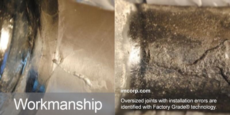
Guest Article: IMCORP
uploaded by Natalie Lundie – Thorne & Derrick Supply Chain: Marketing Lead
IMCORP is a provider of underground power cable reliability services for medium and high voltage (5kV to 500kV) power cable systems for both aged and new cable installations.
IMCORP’s Factory Grade® technology will access MV HV Cable Systems, identify cable systems in need of rehabilitation allowing the customer to ultimately restore the cable system to like-new status.
OVERVIEW
Oversized joints with installation errors are identified with the Factory Grade® technology.
CHALLENGE
Identifying root cause of multiple cable joint failures and substandard performance after a Factory Grade® assessment.
RESULTS IMCORP’s
IMCORP’s Factory Grade® technology effectively identified incorrectly sized joints and provided critical information to improve product selection and installation practice.
Our utility client asked us to assist in identifying the root cause for the multiple joint failures on several two year old substation exit feeders.
Initial assessments with IMCORP’s Factory Grade® technology revealed several substandard pre-molded joints. The utility asked IMCORP to provide a dissection and root cause analysis for two joints excavated from the field. One faulted in service prior to the assessments and the other was serviceable but showed substandard performance.
The dissection and root cause analysis produced evidence of electrical (or carbon) treeing between the inside surface of the joint and the cable insulation (the joint interface). Electrical treeing was observed at the same location in both joint samples only treeing is much more extensive in the joint that failed in service.
Electrical treeing started near the connector (where the Faraday cage makes contact with the cable insulation) and grew along the interface towards one end of the joint. (Figure 1).
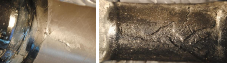
Figure 1 Evidence of electrical treeing was observed on the inside surface of both the serviceable joint with substandard PD activity (left) and the faulted joint (right).
Comparisons of the manufacturer’s catalogue product size selection table and the cable diameter revealed these were the loosest fitting of three models covering this cable size range. A looser fitting joint increases the likelihood of interfacial voids and other installation errors leading to substandard performance.
Voids and stress enhancements in the presence of sufficient voltage stress gives rise to partial discharge, erosion, electrical treeing and eventually failure. Other workmanship issues identified included incorrect dimensions, contamination on the interface, and little to no evidence of void filling grease applied at the cable’s semicon cutbacks.
The utility learned the value of a Factory Grade® assessment since the substandard performance was only observable at 1.5 times the operation voltage and would have been completely missed if the assessment was only performed at operating voltage.
By partnering with IMCORP our client utility gained critical knowledge about their joint performance and soon made significant changes to their joint specification and retrained their installers.
IMCORP is the technology leader in Medium & High Voltage Power Cable Systems life cycle condition assessment and performance – IMCORP have been helping their clients achieve maximum cable reliability for more than 20 years and have assessed over 130,000 5kV to 500kV cable systems spanning in excess of 160 million feet.
THORNE & DERRICK
T&D are Specialist Distributors to UK Distribution Network Operators (DNO’s), NERS Registered Service Providers, ICP’s and HV Jointing Contractors of an extensive range of LV, MV & HV Jointing, Earthing, Substation & Electrical Eqpt – this includes 11kV/33kV/66kV cable joints, terminations and connectors for both DNO and private network applications.
Contact our UK Power Team for competitive quotations, fast delivery from stock and technical support or training on all LV-HV products.
All international sales enquiries can be serviced and supplied by our Export Power Team.
Key Product Categories: Duct Seals | Cable Cleats | Cable Glands | Electrical Safety | Arc Flash Protection | Cable Jointing Tools | Cable Pulling | Earthing | Feeder Pillars | Cable Joints LV | Joints & Terminations MV HV

Network Renewal With Environment-Friendly Pfisterer Cable Terminations
August 6th, 2021
Pfisterer Cable Terminations
Spanish grid operator i-DE Redes Eléctricas Inteligentes, member of the Iberdrola Group, is using the advantages of the new oil and gas free retrofit cable terminations from PFISTERER for the renewal of its network infrastructure.
They allow the existing cable to be retained when ageing terminations are replaced. Easy to install, they also safeguard the environment in the long term.
")
Alroc Tools – Cable Jointing Tools (MV HV)
i-DE Redes Eléctricas Inteligentes, based in Bilbao, is one of Spain’s main grid operators. Like many network operators, it faces the challenge of long-term infrastructure renewal.
Networks have to be maintained, updated and brought into line with future requirements. In this case, the task was to replace ageing porcelain terminations on a 132 kV line in the Madrid metropolitan area. A modern solution was sought, but one that did not necessitate changing the existing cable.
“This is a typical requirement that we meet with our push-on EST retrofit terminations. In principle they are suitable for all XLPE cables up to a conductor cross-section of 2,500 mm². However, the solution can also be adapted for other cable types – such as here for i-DE, where an EPR cable is used.
It is compatible with substation and transmission tower installation, is easy to fit and maintain, and it is sustainable,” explains Tarek Fahmy, Senior Product Manager at PFISTERER.

PFISTERER Retrofit i-DE Spain
Environmentally safe and flexible
Whether in the substation (with or without integrated surge arrester), as a flexible solution or on the transmission tower – with its dry retrofit terminations, PFISTERER offers a comprehensive range for all requirements and voltage levels from 72.5 to 170 kV, tested in accordance with IEC 60840.
The advantage with these solid-insulated, oil and gas free terminations is that they are explosion-resistant with no risk of leakage in the event of a fault, and there is no environmental hazard at any time. Plus the terminations are maintenance-free over their entire service life.
“As well as the installation and maintenance cost savings, the environmental aspect is just as important as it allows us to sustainably renew our energy infrastructure,” says Jose Miguel Sánchez Pereira, Maintenance Manager EHV Lines Centre Region at i-DE. The PFISTERER solution meets all of the grid operator’s needs.
It has been in use since November 2020 in a substation and on a transmission tower, each with six terminations. And its flexibility is already apparent: the new terminations can be used as a self-supporting version or in existing support structures, and are also easier and faster to install thanks to their low weight.

Pfisterer
The Pfisterer corporate group has been dealing with the interfaces in the flow of electricity ever since it was founded back in 1921.
As a specialist in energy transmission and distribution, Pfisterer offer our customers and business partners a range of sophisticated, future-ready products: For all voltage ranges and wherever reliable, long-lasting systems are needed for powerful energy grids.
As well as the energy sector, they are also active in transport technology and industrial solutions.
SICON SHEARBOLT CONNECTORS
The Right Connection for All LV MV HV Conductors – For years, bolted clamps, connectors, and cable lugs have been gaining ground – with good reason. Bolted connectors offer technical and practical advantages that compression technology cannot match.
Bolt type connectors offer not only technical, but also practical advantages over compression technology. All SICON Shearbolt Cable Connectors cover a wide conductor cross-section range so that you always have the right connectors on site for any application.
Main benefits of Sicon Connectors include:
- Reliable connection for all conductors
- Optimal contact force for all conductors
- No damage to individual strands
- Installation with standard tools
- Ideal for all type of joints or terminations
- Wide application range

LV MV HV Jointing, Earthing, Substation & Electrical Eqpt
Key Product Categories: Duct Seals | Cable Cleats | Cable Glands | Electrical Safety | Arc Flash Protection | Cable Jointing Tools | Cable Pulling | Earthing | Feeder Pillars | Cable Joints LV | Joints & Terminations MV
Subsea Power Cables in Shallow Water | DNVGL-RP-0360
August 6th, 2021
This Document supersedes DNV-RP-J301, February 2014.
Thorne & Derrick can provide Joints, Terminations & Connectors for the safe and reliable operation of subsea power cable systems up to 66kV – this includes cable accessories utilising Heat Shrink, Cold Shrink and EPDM Rubber type connection and termination products from market-leading manufacturers including 3M Electrical, Pfisterer CONNEX, Nexans Euromold and NKT.
Further Reading
- Cable Grips | Supporting Inter-array, Export, Umbilical & Subsea Cable Installations
- Nexans Subsea Solutions For Power Networks
- How To Install A Subsea Cable – Power Networks
- How To Remove Bitumen From Subsea Cables & Umbilicals Using Socomore Wipes
- Avoiding Subsea Cable Failures Before They Hit The Water
- Subsea Power Cables For North Sea Link Interconnector Project

Thorne & Derrick are Specialist Distributors to the UK and international Offshore Wind & Renewable industry to provide safe and reliable LV HV Electrical Cable & Power Distribution Systems up to 66kV – we are highly customer responsive and absolutely committed to providing a world-class service.
Contact our UK Power Team for competitive quotations, fast delivery from stock and technical support or training on all LV-HV products.
Key Product Categories: Duct Seals | Cable Cleats | Cable Glands | Electrical Safety | Arc Flash Protection | Cable Jointing Tools | Cable Pulling | Earthing | Feeder Pillars | Cable Joints LV | Joints & Terminations MV HV

See how T&D support, supply and service the Renewable Energy industry.

MV HV Cables 11kV 33kV 66kV | Cable Joints, Terminations & Connections
PFISTERER Connex | Separable Connectors Specification Guide for Medium Voltage Electrical Systems
July 23rd, 2021
PFISTERER Connex | Stocked & Distributed in the UK by Thorne & Derrick
The following guide is designed to help with the specification of PFISTERER CONNEX Separable Connectors size 0 – 3/3-S. You can access the form using the link below.
PFISTERER Connex Separable Connectors
Thorne & Derrick provide competitive prices and fast delivery from stock for the complete range of LV MV HV Power Products manufactured by Pfisterer – this includes Pfisterer CONNEX MV HV cable plugs and terminations.
The application, cable and MV-CONNEX Separable Connector need to be matched.
Only adapted connectors can achieve the required reliability in the grid.
For cables according to DIN VDE standard, a simplified selection process is possible.
See the beginning of “Section B”.
For cables that have not been produced to comply with DIN VDE, a product configurator is used to determine an individual article number for the required MV-CONNEX Separable Connectors size 0-3/3-S. In order to be able to define the article number, the Specification Form for MV-CONNEX Separable Connectors must be completely filled-in by the project specialists of the customer.
The individual article number consists of a 9-digit number plus an optional variant code. This article number contains all parts for connecting and earthing the individual cable. This article number is marked as Set – which means 3 pieces of the same connector.
Please find instructions below, which will help to correctly fill in the CONNEX Specification form.
The parameters needed can be separated into two groups:
A. Application specific parameters
B. Cable specific parameters
Please complete section ‘A’ and ‘B’.
Section A: Application specific parameters

GIS/Trafo Socket
The cable connector and the socket have to be the same size. The electrical parameters and dimensional measures are defined in the standards EN 50180 and EN 50181.
The following details might help you:
- size 0: lᴺ=250A; Uᵐ=24kV
- size 1: lᴺ=630A; Uᵐ=36kV
- size 2: lᴺ=800A; Uᵐ=42kV
- size 3: lᴺ=1250A; Uᵐ=42kV
- size 3-S: lᴺ=1250A; Uᵐ=52kV
It is important to know the size of the socket of which is installed in the switchgear or the transformer.
Application
Depending on the application some special materials and/or additional components are needed.
For application “offshore” or for application “soil-resistant”, special material for housing and sealing is provided.
The section”offshore” should also be ticked if the application is in a coastal area where there is a saline/corrosive atmosphere. Soil-resistant is used if the cable connector itself is underground.
Lowest Ambient Temperature
The standard ambient temperature range is from +50ºC down to -25ºC. For applications where the ambient temperature goes down to -45ºC a special low temperature grease is needed. The temperature directly around the Separable Cable Connector is relevant.
Please note that for indoor application the decisive factor is the ambient temperature inside the building.
Connector Plug-in Location
Only for single sockets installed from inside of the equipment (not relevant for transformer elbow bushing or cast resin joints).
If the application is “outdor” and if the socket entry is from the top, an additional sealing system has to be applied. This is needed to prevent rain/water from entering the connector.
Therefore, please indicate if the position of installation is “top entry” or “other” (not top entry).

Voltage Tap
The voltage tap serves as an interface for a continuous voltage indicator system (DSA-LRM, DSA-2, DSA-i3). This is used to ensure the absence of voltage in the cable system before working on the cable system. For the indication of voltage, a separate product is needed (not in the scope of supply of the connector). To connect this voltage indicator system, the voltage tap (additional components) has to be included in the connector kit. Please indicate “yes” if needed.
standard is “no”
Section B: Cable specific parameters
For cables according to DIN VDE standard, a simplified process is possible. To select the connector, only “cable type”, “cross section”, “voltage level” and “section A” are required.
The simplified process is valid for the following cable types:
| N2XS2Y RM | N2XS(F)2Y RM | N2XS(FL)2Y RM |
| NA2XS2Y RM | NA2XS(F)2Y RM | NA2XS(FL)2y RM |
In case of non-DIN VE cables, please indicate all the cable parameters.

Cable Design
Single core cable or three core cable.
A three core cable only has to be indicated if the accessories for cable break out have to be included in the cable kit. If those accessories are not needed as they are e.g. already supplied in scope of project, single core cable can be selected (please indicate cable screen and armouring only for the single core cable).
Voltage Level
Voltage level of the cable
U⁰ = phase to earth voltage
Uⁿ = nominal voltage; phase to phase voltage
Uᵐ max. operating voltage (2 x U⁰)
Common voltage levels as reference:
| U⁰ (kV) | Uⁿ (kV) | Uᵐ (kV) |
| 3,6 | 6 | 7,2 |
| 3,8 | 6,6 | 7,2 |
| 6 | 10 | 12 |
| 6,6 | 11 | 12 |
| 8,7 | 15 | 17,5 |
| 12 | 20 | 24 |
| 12,7 | 22 | 24 |
| 15 | 20 | 24 |
| 15 | 25 | 30 |
| 18 | 30 | 36 |
| 19 | 33 | 36 |
| 20,8 | 36 | 42 |
| 26 | 42 | 52 |
Conductor Cross Section
Cross Section is only a reference value and does not influence component selection.
Conductor Diameter & Type
The contact system consists of several components. The components are selected according to the conductor type and the diameter of the conductor. The diameter of the bare conductor is relevant (without semi-con conductor screen).
The components have a designed working tolerance in which the can be used. During cable preparation and connector assembly, the conductor diameter has to be within this tolerance, for the contact system components to fit properly.
Conductor types (IEC 60228):
![]() RM: stranded circular (class 2)
RM: stranded circular (class 2)
SM: stranded sector
RE: solid circular (class 1)
SE: solid sector
RF: super-flexible stranded (class 5+6)
The standard is RM stranded circular (class 2).
Insulation Diameter
The insulation diameter defines the correct insulating part of the connector. The diameter of the bare insulation (without semi-con insulation screen) is required.
The insulating parts have a designed working tolerance in which they can be used. During cable preparation and connector assembly the insulation diameter has to be within this tolerance, for the insulating part to fit properly.
Semi-Conductive Insulation Screen
Depending on the semi-conductive screen type and layer thickness, a special assembly method with special components is used.
- Fully Bonded: The semi-con insulation screen is removed with a cable peeling tool. Standard for DIN VDE cables. Standard thickness is ≤ 1mm; in case thickness is ≥ 1mm please indicate the thickness of semi-con layer.
- Easy Strip: The semi-conductive insulation screen can be removed without a cable peeling tool.
- Graphite: The cable has a layer of graphite on the insulation. This could be the case with older cables, but is not common with new cables.
- Without Semi-conductive Layer: if a low voltage cable or a medium voltage cable with only 2 kV voltage level is used the insulation could be without semi-con insulation screen.
The standard is fully bonded, thickness ≤ 1mm.
Cable Screen
Depending on the cable deign the cable core could have one or more metallic layers. If these metallic layers are indicated on the specification form (Cable screen, 1st and 2nd armoring) corresponding accessories to connect and to ground these layers are supplied.
Diameter values are over each metallic layer.
The standard is: cable screen = Cu wire screen, without 1st and without 2nd armouring.
- Wire: made from Cu or Al
- Laminated foil ( ≤ 0,1 mm): made from Cu or Al
- Tape: made from Cu or Al
- Lead Sheath: made from Pb
- Corrugated Sheath: made from Cu or Al
- Wire Mesh: made from Cu
If your cable had another special cable screen, please indicate this on the form, e.g. fibre optics or up to 3 separate earthing leads (3 core cables).
Outer Cable Jacket
Diameter of the complete cable. For cables with very big or very small diameters, a special assembly method with special components is applied.
PFISTERER
The Pfisterer corporate group has been dealing with the interfaces in the flow of electricity ever since it was founded back in 1921.
As a specialist in energy transmission and distribution, Pfisterer offer our customers and business partners a range of sophisticated, future-ready products: For all voltage ranges and wherever reliable, long-lasting systems are needed for powerful energy grids.
As well as the energy sector, they are also active in transport technology and industrial solutions.
LV MV HV Jointing, Earthing, Substation & Electrical Eqpt
Key Product Categories: Duct Seals | Cable Cleats | Cable Glands | Electrical Safety | Arc Flash Protection | Cable Jointing Tools | Cable Pulling | Earthing | Feeder Pillars | Cable Joints LV | Joints & Terminations MV
