

Cable Joints & Terminations HV
Cable Testing – Is Resonance Testing The Way Forward For Offshore Wind?
June 15th, 2021
-
Reproduced with kind permission of Calum Galvin from Mane - Worldwide Recruitment Specialists
Offshore Wind
Cable Testing of Medium Voltage Power Systems & Accessories
Imagine this: Right before the winter season, something goes wrong at an offshore wind farm. There’s a fault somewhere in one of the long submarine cables that carry the generated electricity to land.
But with storms raging and the testing season almost over, nobody can get out there to run a high-voltage test on the cables. There’ll be no way to find the fault until at least April – which means no electricity. The turbines spin all winter for nothing, while the power company bleeds money.
Conventional cable testing systems aren’t designed to be used in the middle of the ocean.
Salty air, rain, snow, and stormy seas make it impossible to operate them reliably. And you can’t exactly pitch a tent over them. Then there’s the difficulty of getting people to the site to carry out the tests. It’s only possible for a few months of the year, and even then it takes considerable advance planning.
This means offshore wind companies have resigned themselves to the use of SOAK tests (a 24-hour test with only nominal voltage) to test cables. But with cables getting longer, and often being made without joints, these tests are becoming increasingly inadequate. Practical and weatherproof testing systems for offshore cables are urgently needed.
Offshore wind is the leading form of renewable energy, and wind turbines are constantly increasing in power. For new wind farms, the operating voltage of the submarine cables that deliver the electricity is being increased to 66kV.
The International Electrotechnical Commission (IEC) has therefore greenlit a second form of testing for operating voltages over 36kV: resonance testing.
Rather than using nominal voltage like the SOAK test, resonance testing actually reproduces the load on a cable operating normally at normal voltage and grid frequency. The test is carried out using a resonant circuit made up of a test inductor (inductance) and a test cable (capacitance). The test system supply has a variable frequency which is automatically set to the test circuit’s resonance frequency, minimising the feed-in power needed.
Resonance testing can also reliably detect installation errors – which are the cause of over half of all problems on offshore wind farms.
The resonance testing system offers wind farm operators, testing service providers, cable manufacturers the flexibility they need to keep complex offshore wind infrastructure functioning continuously, all year round.
And if something does go wrong just before the end of the testing season, resonance testing will enable them to quickly test the systems, fix the problem and keep the winter wind generating power.
- More By Mane Contract Services – Why Large Offshore Wind Farms Should Double Their Intra-Array Voltage


See how Thorne & Derrick support, supply and service the Renewable Energy industry.
Insight
by Ross Piercey | Asset Manager at JDR Cable Systems
Insurers want confidence in power systems – the weakest part of the inter array system is the cable accessories. The resource pool for Competent Jointers is shrinking due to high demand meaning quality of Jointing & Terminating workmanship can fluctuate.
The conditions they are fitted in are not that of labs.
Given over 50% of failures are cable accessories, a PD monitored, resonance test at power frequency does give early indications of potentially critical issues with cable preparation.
Furthermore, understanding PD inception voltages when testing at power frequency gives a much better indication of a “hard working” array cable. Resonance may practically be an issue, but we are an industry and business who thrives on a challenge. The Carbon Trust and others are looking at testing options and this issue needs addressing at an industry level, the cost of failure, dictates we must.
VLF /DAC are great tools but some feel they do not excite failure modes enough to be picked up but PD analysis is helping this, but offshore this is not without its issues. JDR are already bidding resonance for numerous clients, before the year is out we will resonance test with a state of the art purpose built system offshore, watch this space.

Global energy companies depend on high performance subsea umbilicals and cables to provide power and control in the world’s harshest offshore environments. JDR is a leading provider of technology connecting the global offshore energy industry.

Thorne & Derrick are Specialist Distributors to the UK and international Offshore Wind & Renewable industry to provide safe and reliable LV HV Electrical Cable & Power Distribution Systems up to 66kV – we are highly customer responsive and absolutely committed to providing a world-class service.
Contact our UK Power Team for competitive quotations, fast delivery from stock and technical support or training on all LV-HV products.
Key Product Categories: Duct Seals | Cable Cleats | Cable Glands | Electrical Safety | Arc Flash Protection | Cable Jointing Tools | Cable Pulling | Earthing | Feeder Pillars | Cable Joints LV | Joints & Terminations MV HV

Partial Discharge Secrets, Tips & Tricks by William Higinbotham (President) at EA Technology
June 7th, 2021Partial Discharge
-
Special Thanks To William Higinbotham President at EA Technology for allowing T&D to republish
Most of us started our electrical careers with fairly good knowledge about the practical aspects of our jobs. We understood voltage, current, power, resistance, etc.
We mastered the more esoteric areas such as electrical fields and electrical stress control and only revisited these topics if our day-to-day job required it. Partial discharge (PD) is one of those areas where we might have learned how to identify it or how to use a test set, but most of our roles have not exposed us to the ins and outs of this topic.
In this article, I share some unexpected things I have learned while working with clients on partial discharge issues. I hope this includes the secrets, tips, and tricks you always wanted to know about partial discharge but were afraid to ask.
Can Cable Termination Mistakes Cause PD?
When a termination containing multiple layers and different materials is exposed to an electric field, the voltage stresses are larger in the areas of lesser permittivity.
Air has a permittivity about 2.3 times lower than insulation, so a void in the termination will have approximately 2.3-times-higher field stresses. Combined with a 10-times lower dielectric strength, this leads to discharge across the void.
Cable terminations are specifically engineered to ensure voltage stresses do not exceed the insulation capability at any point. This is accomplished by ensuring the voltage gradients across the insulation are even (Figure 1).
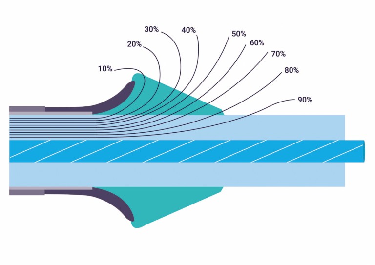
FIGURE 1 VOLTAGE GRADIENTS IN A CABLE TERMINATION
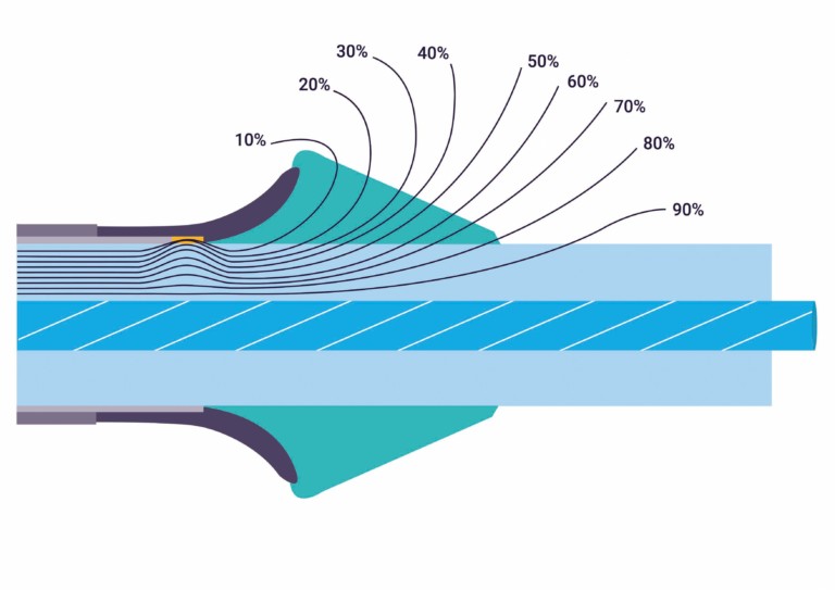
FIGURE 2 VOLTAGE GRADIENTS IN A POOR TERMINATION
Voids can be caused by common mistakes in terminations. Failure to completely fill gaps between insulation and conductors with mastic is very common. Imprecise trimming of semiconductor layers can leave a void where the stress tube cannot fill the poorly trimmed section. Failing to fully clear the semiconductor layer off the insulation causes a concentration of stress and results in PD even if there is no void. Figure 2 shows that electrical stress is greater in and around the void.
Cable termination procedures are precisely engineered, and any failure to follow them closely can lead to voids, field concentration, and partial discharge. An example of this can be seen in Figure 3, where an overly large gap that was not filled with mastic led to failure.
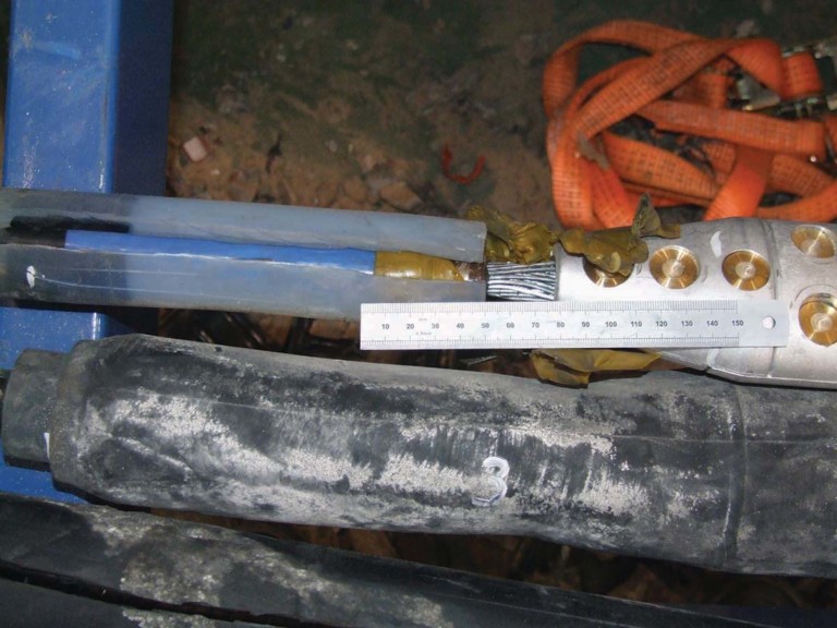
FIGURE 3 DEFECTIVE CABLE TERMINATION
Can Incorrect RFCT Placement Induce PD?
When performing an online partial discharge test on a cable, a radio frequency current transformer (RFCT) must be attached to the cable ground strap. In placing the RFCT, think 95% about safety and 5% about getting a good signal. Improper placement of an RFCT can affect both safety and signal.
For safety reasons, ensure you have a solid ground capable of withstanding any phase-to-shield fault current. Also ensure the RFCT is away from the termination and close to the ground bar so the RFCT is still safe if the ground does separate. Figure 4 shows an RFCT placed on an adequate ground close to the main ground bar and away from the termination.
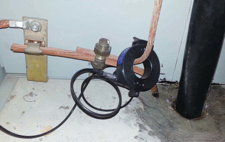
FIGURE 4 PROPERLY PLACED RFCT
Is that the only reason you put the RFCT away from the termination? Remember that the termination is where the electric field goes from nice and contained inside the shield to free and unrestrained after the shield cut-back. The termination is designed to allow the field to spread out gradually so there is a lesser field but evenly distributed around the termination.
The closer you get to the termination, the stronger the field becomes. Allowing the RFCT inside that field can induce PD. It probably will not lead to failure unless it is very close, but it will make it impossible for that RFCT to discern any real PD.
What Are Contact Discharge and Floating Metal Discharge?
Contact discharge is caused by a poor high-voltage connection where sparks can jump across the gap at set times on the sine wave when the voltage level is high enough. These defects usually produce heat as well as ultrasonic sound that can be detected.
A related discharge — floating metal discharge — is an electrical discharge that takes place due to floating metal in the electric field. The floating metal typically acquires an electric charge from the field and then discharges to ground, the conductor, or via corona through the air. Common examples include tools or hardware left in a cabinet after work is performed.
Contact discharge and floating metal discharge have characteristic phase resolved partial discharge (PRPD) plots where the level of discharge is consistent as the voltage increases (Figure 5). These two types of discharge emit similar patterns, so it can be difficult to differentiate between the two.
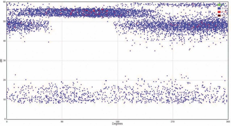
FIGURE 5 PHASE RESOLVED PARTIAL DISCHARGE PLOT
The phase resolved pattern indicates that PD magnitude does not change despite the change in voltage. This is because the distance from the gap at the poor HV connection or the floating metal to the live conductor is constant; therefore, the flashover voltage remains the same.
The discharge phase angle actually moves with each succeeding discharge due to the physics of this type of discharge. The variance in phase and consistency in discharge amplitude produces these characteristic flat, broad lines in the PRPD. This characteristic can be used to identify this type of discharge and make it easier to find the offending component.
Contact discharge can cause failure due to the poor HV connection, whereas floating metal discharge tends not to lead to catastrophic failure. Both discharge types create a strong signal that often masks more damaging types of discharge. Ensure you eliminate this so you can see other discharge sources.
Is It Better to Ground the Cable
at One End or Both?
When you design a cable system, you have an option of grounding the shield at one end or both ends. If one end is ungrounded, a sheath voltage limiter (SVL) is typically placed on that end. The shield of a cable capacitively and inductively couples to the conductor, thereby acquiring potentially dangerous voltage.
If both ends are grounded, the sheath voltage will be lower than if one end is an open circuit, especially during a fault. The downside of grounding both ends is that circulating currents can heat the cable and reduce its ampacity.
If a cable grounded at one end shows PD, the current has nowhere to go except the ground strap where the RFCT is located. This allows you to measure the total PD current. If the cable is grounded at both ends, the PD current will divide according to the ratio of impedances in either direction. This gives a lower reading.
However, there is a bright side: Testing both ends of the cable allows better sensitivity overall. A small discharge on one end might not be detectable at the other end.
Is There a Standard for Acceptable
PD Levels in Cables?
The world of electrical testing is largely predicated on the fact that we can assign a threshold. Above the threshold is considered bad, and below the threshold is considered good, or vice versa.
As an example of the latter, in an insulation resistance test at 1kV, above 100 Megaohms is generally considered good for many equipment types while below 100 Megaohms is suspect or bad. These test methods and thresholds are codified in international, peer reviewed, and balloted standards to ensure they are accurate.
The world of partial discharge testing has very few approved standards, and most of them contain vague words like “should” and “may” instead of “shall” and “must.” Cable PD testing is especially void of standards that include hard and fast thresholds. ANSI/NETA MTS 2019 is the first United States standard to include online PD testing, but it doesn’t cover cables. IEEE 400.3 is specifically for field PD testing of cables, but it has no thresholds.
This lack of standardized acceptance levels can be traced back to the very nature of PD. It is an unfortunate fact that the absolute PD level is not directly relatable to the likelihood of failure or the time to failure. PD levels go up and down with a variety of influencing factors: Voltage, current, ambient temperature, relative humidity, time since inception, defect carbonization, and other factors.
With all these variables unrelated to the test method, it is difficult to arrive at threshold levels. Trending over time or comparison to similar assets remains the best way to gauge the severity of PD. You may not be able to predict when something will fail, but you can identify bad actors for further study.
Which Is Better — Online or Offline PD Testing?
This is a bit of a trick question. The tests are quite different, and they tell us different things. Both have their place in any maintenance and reliability program. It is important to understand their different strengths.
Online PD Testing is usually the first step. You can test all your assets quickly and efficiently to see what is good and what needs further study. You are testing under real-world conditions of voltage, current, frequency, and load. If PD does not exist in the real-world conditions, there is no need to be too concerned.
You can test all your assets without taking anything out of service or opening any panels to do the tests.
Typically, a very small percentage of assets record any PD. The downside is that online PD testing will tell you less about PD than an offline test.
Offline PD Testing is as close as you can get to factory testing in the field. You can vary voltage and see noise-free PD patterns. You can see exactly at what voltage PD begins and ceases.
Unfortunately, it’s not all good news. You must take the equipment out of service and bring in large, heavy, expensive test equipment. You are also not working in a real-world condition, so results may not be fully representative of normal conditions.
An offline test takes 10 to 20 times longer than an online test. The frequency is typically not power system frequency, and there is no load current, so the temperature profile is also different.
The global best practice is to do online testing or monitoring on all assets and do offline tests on the small population of assets that give indications of PD online.
Can You Find PD Inside Switchgear by Testing the Cable?
Transient earth voltage (TEV) is a standard technique for finding partial discharge inside medium-voltage metal-clad switchgear. The TEV effect, discovered in the late 1970s by Dr. John Reeves of EA Technology, has become the basis for non-invasive testing for internal discharge.
Voltage is induced on the outside surface of metal-clad gear as a result of discharge inside the gear. This voltage is a narrow pulse of a few microseconds and amplitude in millivolts. Measuring TEV can be very difficult because the signals of interest are hidden in noise.
One trick we have learned is that performing a TEV test on the outside of a cable exiting the cubicle is an excellent way to find PD inside the cubicle. A TEV probe on the outside of the sheath will couple to the shield and often provide a higher signal than the outside of the switchgear.
The PD pulse in the switchgear will travel down the conductor and radiate to the shield. However, gaining access to the cables within a meter of the switchgear is not always possible. With IEC-type gear, the cables are exposed. In most cases with ANSI gear, you will need access below the cabinet. Many industrial substations are raised or have a basement that allows access. If at all possible, try it out.
How Soon After Energizing Can You See PD?
Traditional knowledge held that partial discharge took years or decades to develop. The standard response was “all my equipment is new! I don’t need to do PD testing.”
In some instances, PD takes a long time to start. The thermal cycling that occurs throughout device operation can cause voids over time, and internal discharge can take decades to cause failure. However, as we have learned recently, early-life PD and failures are quite common.
The oil sands region of Alberta, Canada, has seen explosive growth in the past 25 years, and the demand for jointers outstripped the qualified supply. Cable failures within the first 12 to 18 months were common. Data centers and windfarms have similarly driven cable installation rates to rise, and early failure rates in those applications are well above acceptable levels.
If the conditions are right for PD, there is no physical reason for it not to start immediately. It may be so low as to be undetectable at first, but it can be present. PD is more likely to be caused by workmanship than by aging, and bad workmanship is there from day one.
In Figure 6, a monitoring system was installed on a cable with new splices; PD was detectable by day 10. By day 14, it was 300 pC — not quite ready to fail, but clearly a rapid increase immediately after energizing.
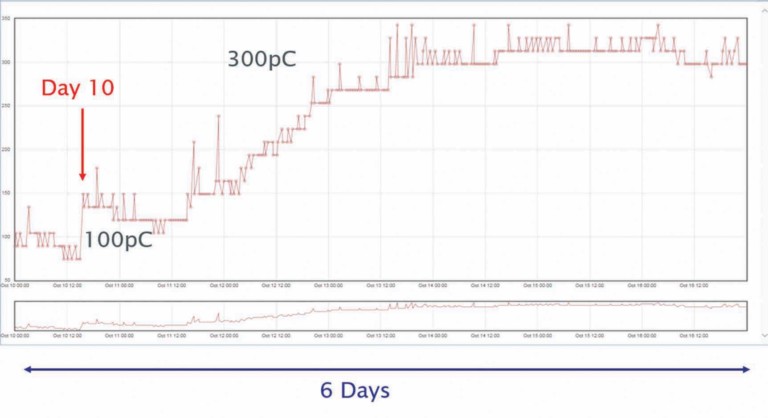
FIGURE 6 PARTIAL DISCHARGE OVER TIME
Figure 7 is an EHV termination that failed within days of energization. PD would have been detectable immediately.
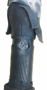
FIGURE 7 FAILED EHV TERMINATION
Conclusion
I hope these few examples have been interesting and enlightening. While partial discharge is still a developing topic in our industry and we continue to find new things every day, the information we can learn about our assets is worth the learning curve.

William G. Higinbotham has been president of EA Technology LLC since 2013. His responsibilities involve general management of the company, including EA Technology activities in North and South America. William is also responsible for sales, service, support, and training on partial discharge instruments and condition-based asset management. He is the author or co-author of several industry papers.


Thorne & Derrick distribute the most extensive range of Low & High Voltage Cable Installation & Electrical Distribution Equipment to the Power Transmission & Distribution industry in the onshore and offshore wind, solar, rail, oil/gas, data centre, battery storage and utility sectors.
We service UK and international clients working on underground cables, overhead lines, substations and electrical construction at LV, 11kV/33kV and up to and EHV transmission and distribution voltages.
Key Products: MV-HV Cable Joints & Terminations, Cable Cleats, Duct Seals, Cable Transits, Underground Cable Protection, Copper Earth Tapes, Cable Jointing Tools, Feeder Pillars, Cable Ducting, Earthing & Lightning Protection, Electrical Safety, Cable Glands, Arc Flash Protection & Fusegear.
Distributors for: 3M Electrical, ABB, Alroc, Band-It, Cembre, Centriforce, CMP, Elastimold, Ellis Patents, Emtelle, Furse, Lucy Zodion, Nexans Euromold, Pfisterer, Polypipe, ProGARM, Prysmian, and Roxtec.
- Scope –single-source supply of extensive range of products
- Stock – a multi-million pound stock holding provides complete global supply solutions
- Staff – technical support from a trained, proactive and friendly team
- Delivery – UK stock turnaround with express logistics to all international destinations

HVPD Case Study | Offline TDR Testing of a 25kV Cable for Rapid Transit Organisation
May 21st, 2021
-
Special thanks to Harriet Robertshaw at HVPD for the kind permission to republish
Medium Voltage Project
Following the visual identification of a fault in a 25kV cable, a Rapid Transit Organisation in the UK had a requirement to locate the presence of any further faults across its cable network, which was approximately 40 years old.
Offline Time Domain Reflectometry (TDR) testing was conducted across three sections of 25kV trackside PILC to pinpoint the locations of any further insulation degradation present.
Solution
- HVPD Pulse Generator
- Diagnostic Unit
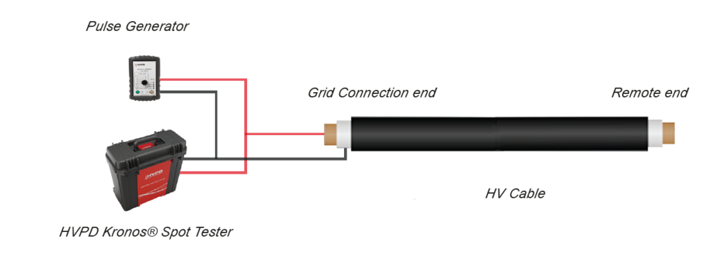
Offline TDR testing was conducted from the known failure point of the cable, back to each cable sealing end termination using an HVPD Diagnostic Unit.
Offline TDR testing was also conducted on an additional cable section from an Overhead Line Equipment (OLE) switch. The cable was mapped using a Pulse Generator.
Background Theory
Offline TDR is performed by injecting a low voltage pulse onto the core of the cable under test. High changes of impedance within the cable will create reflections of the original injected pulse.
These areas of high impedance change can typically be attributed to either cable faults or joints and therefore analysis of these pulse reflections can indicate fault and joint locations. TDR can also be used as a tool to verify the total length of the cable if this is unknown.
The test is carried out by measuring the injected pulse return time (i.e. the time for an injected pulse to propagate from one cable end and back) in order to provide the locations of changes in impedances, such as cable joints and the end of the cable. TDR testing is utilised to provide accurate fault location data in cables.
Background Theory
Results
Initial results showed that there were no visible impedances relating to cable joints or faults in the cable section located from the original failure point back to sealing end terminations.
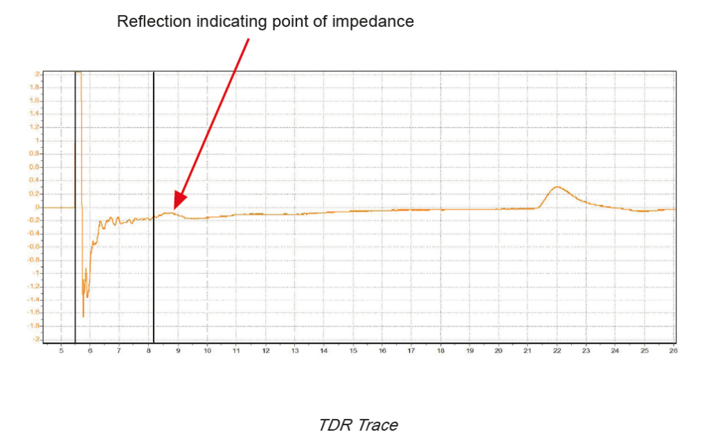
However further testing of the cable section leading back to an OLE switch demonstrated a large impedance change not associated with any known joint location. This impedance location was observed to be approximately 239 meters from the test location.
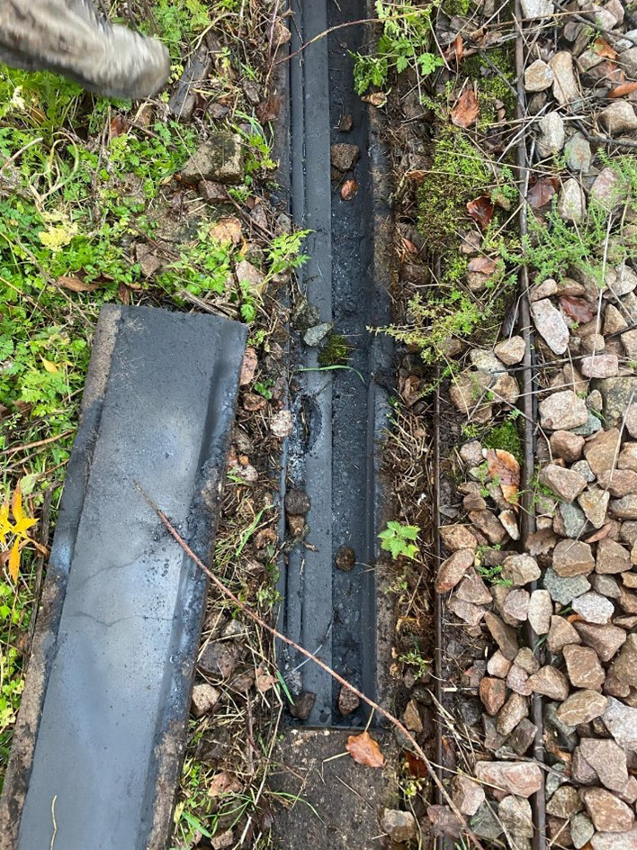
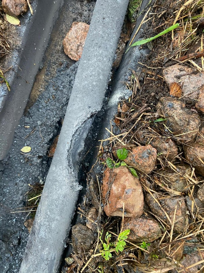
Following this observation, a visual inspection along the identified cable section route was performed. Upon lifting the cables covers at approximately 241 meters along the cable from the test point a visibly clear cable fault was identified.
TDR Trace
Inspection of Cable Fault Location
Conclusions and Recommendations
- Offline TDR testing revealed an unknown cable fault, which had the potential to cause further risk of an in-service cable failure
- The cable section with the fault was subsequently removed and cable repaired
- Further TDR testing is required on this cable and additional cables in the network to determine if any other points of degradation are present

About HVPD
HVPD supplies a comprehensive range of equipment to detect and monitor On-line PD for the condition assessment of in-service power cables, switchgear, motors and generators, and transformers rated at 3.3kV and above. Our PD testing and monitoring technology provide you with an early warning of developing insulation faults, helping you to avoid costly failures and resulting unplanned network outages.
To find out how we can test and monitor your cable network for PD and locate any faults, terminations or joints, get in touch today at [email protected] or call us on 0161 877 6142.

Thorne & Derrick
Specialist Electrical Distributor
Established since 1985, T&D International based in the UK distribute the most extensive range of LV, MV & HV Cable Jointing, Terminating, Pulling & Installation Equipment – contact us today for a competitive quotation.
Key Products : MV Joints & Terminations, Access Chambers, Cable Cleats, Duct Seals, Cable Transits, Jointing Tools, Feeder Pillars, Cable Duct, Earthing & Lightning Protection, Electrical Safety, Cable Glands, Arc Flash Clothing Protection & Fusegear.
Distributors for : 3M, Pfisterer CONNEX, Nexans Euromold, Elastimold, Catu, Roxtec, Emtelle, Centriforce, Lucy Zodion, Alroc, Cembre, Prysmian, Ellis Patents, ABB & Furse.

T&D Providers Of Jointer Training Courses By Pfisterer CONNEX & Nexans Euromold
Five Steps to Landing a Wind Turbine Technician Role
May 20th, 2021
-
Special thanks to Freya Mortimer from Eden Scott for sharing the article
Wind Turbine Technician Role
It’s an exciting time for the wind power industry here in Scotland with the first ever floating wind farm opening on the 18th of October 2018 off the coast of Peterhead and millions of pounds being invested across the board into onshore and offshore wind developments. So what better time to finally break into renewables and make moves to become a wind turbine technician?
Eden Scott have put together a quick ‘how to’ guide covering the basics of preparing yourself for a wind turbine technician job. Whether you’re looking for an entry level position, or you are more experienced candidate looking to move from another industry, these top tips will help you get yourself ready and qualified.
Thorne & Derrick are leading Specialist Distributors & Stockists of LV, MV & HV Cable Installation, Jointing, Substation & Electrical Equipment to the Wind industry.
Complete range of MV Cable Accessories to suit wind energy power cables – this includes joints, terminations and connectors from manufacturers including 3M, Pfisterer, Nexans Euromold and Prysmian.

1. LEARN AND TRAIN
Whether you’re an experienced technician looking to change industries or looking for your first position, there are many companies are willing to train technicians on the job.
However, one of the most challenging parts of landing your first role can be building that initial experience and knowledge. If you’re worried that a lack of background in the industry is holding you back, there are a wide variety of options that will allow you to learn and develop those key skills.
Fife College offers a one year multidisciplinary renewable engineering technician course, and Ayrshire College offers a City and Guilds one year wind turbine technician qualification. Both of these are perfect for aspiring technicians with any level of experience outside of renewables; they will prepare you for the job and show you are ready to work and put your new knowledge into practice.
If a year of studying isn’t for you and you want to get stuck right in, there are quick courses that provide industry and technical insight to add to your existing skillset to give you that extra edge. For instance, the European Energy Centre for instance offer a SQA accredited two days long ‘Wind Power Qualification’ that can be taken online or at Napier University.
2. GET CERTIFIED
Academic courses are a beneficial, but not a necessary stage in targeting technician roles. However, certain qualifications, licenses and certificates are key requirements. Get a driving license if you don’t have one already; not only are a lot of sites in remote locations, but almost all positions will specify a license as a core requirement. You will often be expected to travel to different sites across the country. The good news is, some organisations offer car allowances or access to company vehicles, you just have to bring the license!
Specific turbine qualifications may need to be undertaken. For example, employers frequently look for wind turbine safety rules (WTSR) or Vestas certification. Requirements change role to role so it is crucial you fully read the job description. You can also find a niche and take training courses in specific types of turbine or blade. Although this limits the variety of positions you’d be qualified for, targeting a specific area can give you a strong chance when these opportunities arise.
Inevitably, many courses come with financial implications. They can be completed and paid for yourself on or offline, but some companies may put you through your training so it is crucial you express a will to build these skills from your first contact with the organization. This will show your commitment and puts you at less of a disadvantage against others who may already be qualified.

3. CLIMB!
Working at a height is an integral part of being a wind turbine technician. You also need to be physically fit, so taking up climbing as a hobby is a great way to keep in shape and simultaneously get comfortable with heights. There are plenty of recreational training centers such as Glenmore Lodge and EICA at Ratho that offer classes and certificates at all levels and have the facilities for you to just give it a go by yourself.
It’s also possible to build up some related height experience in completely different industries; taking up work or odd jobs doing window or gutter cleaning actually puts you in very similar environments and shows your capability working in them!
It’s also possible to pick up an industry qualification showing you know the ropes; this is especially beneficial if you’re from a more ‘hands off’ background. For instance, Talon NDT, who have sites in Edinburgh, Aberdeen and Blackpool, offer a variety of training including Industrial Rope Access Trade Association. If specifically targeting rope access roles, it’s commonplace for employers to look for this at level 1.
Specifically involving heights, employers generally require a CSCS work at heights card which can be taken by Construction Support at a variety of UK locations. As with other elements of learning on the job some employers can put you through these courses and certifications, but if you have the means to put yourself through them you’ll be at a strong advantage when applying for positions.
4. KNOW YOUR LINGO, KNOW YOUR FACTS
When applying or interviewing for jobs it goes without saying that some background research into the role and company is a necessary step. However, it is particularly important if you’re looking at entry level jobs or coming from a science or engineering background outside of renewables.
Showing you know what’s involved in the job, the names and details of the turbines, and how they work will not only make you better prepared when it comes to the interview, but show yourself as a knowledgeable candidate who is ready to learn more on the job. Make sure you have the right lingo to reflect your knowledge and interest in the industry; think turbines and blades, not windmills and fans…
If you’re looking into undertaking formal qualifications you will pick up this information on the course alongside more advanced knowledge, but this isn’t the only way to pick up the basics. There is a wide variety of information and easy to understand guides online explaining the ins and outs of turbines, such as on Good Energy’s website.
There are also of plenty wind power and renewable organisations you can follow on Twitter and LinkedIn, such as Scottish Renewables who regularly post updates and articles about the industry. The fresher and deeper your knowledge, the more appealing you are to hiring managers.

5. SHOW YOUR SKILLS
Make sure the right skills and keywords are on your CV.
This is particularly true for service engineers/technicians looking to move into renewables from another industry; a lot of companies are willing to train you up in the sector on the job, but will be looking to make sure the base skills are there.
Does the role look for knowledge of hydraulics or maintenance?
Make those skills clear. It’s worth remembering that this is for the benefit of both employer and candidate. It might be assumed within your current or previous sector that certain skills and experience come hand in hand with the amount of time served and your job title; but hiring managers might not know this. Make sure all technical experience is included even if it’s not related to the wind industry.
Don’t just focus on STEM experience; more and more roles are looking for demonstrable experience of basic IT. Generally this is Microsoft office programs such as Word and Excel, and even if you might not think it’s relevant, it’s worth indicating if you have an awareness and experience of this software.
If your tech skills are feeling a bit out of touch there are plenty of excellent tutorials on YouTube, or if there’s someone quite tech-savvy among your friends or family you could ask them for a quick refreshed course before your interview.
About Eden Scott

Eden Scott opened the doors of our recruitment agency in 2003; with eight consultants equipped with a computer, a telephone, and a passion for the trade. 17 years on, they’ve grown to be a leading Scottish recruitment agency with over 50 consultants, operating in offices across Edinburgh, Glasgow and Aberdeen.
Eden Scott deliver performance centric recruitment solutions specialising in over 20 different markets across permanent contract and temporary roles.
As well as recruitment, they also design and deliver assessment centres, create compelling digital recruitment campaigns and provide services specifically crafted for start-ups and early stage companies.
See how T&D support, supply and service the Renewable Energy industry.

Thorne & Derrick
T&D are Specialist Distributors to the Renewable industry sector of an extensive range of LV, MV & HV Jointing, Earthing, Substation & Electrical Eqpt – this includes 11kV/33kV/66kV joints, terminations and connectors for both DNO and private network applications.
Contact our UK Power Team for competitive quotations, fast delivery from stock and technical support or training on all LV-HV products.
Key Product Categories: Duct Seals | Cable Cleats | Cable Glands | Electrical Safety | Arc Flash Protection | Cable Jointing Tools | Cable Pulling | Earthing | Feeder Pillars | Cable Joints LV | Joints & Terminations MV HV
T&D Providers Of Jointer Training Courses By Pfisterer CONNEX & Nexans Euromold
Cable Terminations & Minimum Air Clearances for Bushings
May 11th, 2021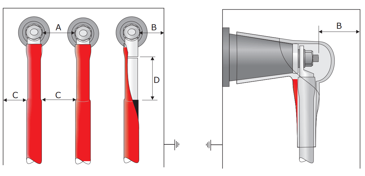
- Check the cable box for minimum clearances and refer to table 1 below.
- If actual dimension ‘A’ and ‘B’ is less than the value given, a bushing boot must be fitted.
| Table 1 – Minimum Air Clearances for Terminations in Cable Boxes in Accordance with BS 164 Class A. | ||||
| Maximum System Voltage, Phase to Phase (kV) | 7.2 | 12 | 24 | 36 |
| Minimum Air Clearance Between Live Metal ‘A’ (mm) | 90 | 127 | 242 | 356 |
| Minimum Air Clearance Between Live Metal and Earth ‘B’ (mm) | 65 | 75 | 140 | 222 |
| Table 2 – Minimum Air Clearances for Terminations in Cable Boxes in Accordance with BS 164 Class A. with Bushing Boots Fitted | ||||
| Maximum System Voltage, Phase to Phase (kV) | 7.2 | 12 | 24 | 36 |
| Minimum Air Clearance Between Live Metal ‘A’ (mm) | 45 | 75 | 100 | 125 |
| Minimum Air Clearance Between Live Metal and Earth ‘B’ (mm) | 32 | 60 | 75 | 100 |
| Table 3 – Minimum Clearance Between Cores and Between Cores and Earth | ||||
| Maximum System Voltage, Phase to Phase (kV) | 7.2 | 12 | 24 | 36 |
| Minimum Clearance ‘C’ (mm) Measured From top of Stress Tubes | 15 | 20 | 40 | 50 |
| Table 4 – Minimum Clearance Between top of The Stress Control Tubing and Base of the Cable Lug. | ||||
| Maximum System Voltage, Phase to Phase (kV) | 7.2 | 12 | 24 | 36 |
| Minimum Clearance ‘D’ (mm) | 30 | 50 | 95 | 250 |
| Table 5 – Impulse Voltage Withstand for Indoor Terminations, Installed With Bushing Boots, on Bushings in Accordance with BS2562. | ||||
| Maximum System Voltage, Phase to Phase (kV) | 7.2 | 12 | 24 | 36 |
| Impulse Withstand Voltage (kV) | 75 | 95 | 125 | 170 |

MV HV Cables 11kV 33kV – Joints, Terminations & Connections
THORNE & DERRICK
Thorne & Derrick are national distributors of LV, MV & HV Cable Installation, Jointing, Substation & Electrical Equipment – servicing businesses involved in cabling, jointing, substation, earthing, overhead line and electrical construction at LV, 11kV, 33kV, 66kV and EHV. Supplying a complete range of power cable accessories to support the installation and maintenance of low/medium and high voltage power systems:
- Slip-on Cable Terminations
- Cold-shrink Cable Terminations
- Heat-shrink Cable Terminations
- Cable Joints – Heat & Cold-shrink
- Separable Connectors (Euromold)
- Surge Arresters & Switchgear/Transformer Bushings
Key Product Categories: Duct Seals | Cable Cleats | Cable Glands | Electrical Safety | Arc Flash Protection | Cable Jointing Tools | Cable Pulling | Earthing | Feeder Pillars | Cable Joints LV | Joints & Terminations MV



