

Earthing
Copper Earth Electrode System Designs By AN Wallis
November 5th, 2020
Copper Earth Electrode System Designs
-
Special thanks to Andy Chaluda Business Development Manager - Technical Services at AN Wallis
Earth Electrode Systems are a critical part of any electrical system, yet are often seen as inert and may sometimes be dismissed as cost-saving or forgotten about until a later stage of the project. But should these earthing systems by AN Wallis fail due to incompetent design or the use of cheap substandard earthing components, the resulting events may be catastrophic to infrastructure or even lethal to people.
Our team of highly experienced professional Engineers & Technicians use the world’s most up to date Electrical Earthing Analysis software package CDEGS to assist in the earth electrode system design process. CDEGS is now recognised as the industry standard earthing design analysis software in the UK and in many other parts of the world.
Our Earth Electrode System Designs not only comply with the relevant National and International Standards, but also follow the ethos of the UK Governments’ Construction, Design & Management (CDM) Regulations 2015.
Some of the areas we are working in are:-
- Electricity Transmission & Distribution Networks
- Electricity Generation sites inc Renewables (Solar, Wind, Anaerobic Digesters)
- Process Plants Static Earthing
- Petrochemical Production
- Telecommunications
- Nuclear EMP
- Rail Traction Substations
- Rail Functional Earthing
- Data Centres
- Airports
CDEGS
The most powerful and accurate suite of commercially available grounding (earthing) and electromagnetic analysis software packages on the market. A complete array of auxiliary software tools are included in the CDEGS suite to complement, support and enhance the methods used to solve various problems involving grounding, electromagnetic interference, electromagnetic fields and transient phenomena that can be tackled by CDEGS.
AN Wallis Earth Electrode System
The 3 areas to analyse with any Earth Electrode system are the Touch, Step and Rise of Earth Potentials (RoEP) also known as Earth Potential Rise (EPR or Ground Potential Rise (GPR).
We will liaise with the DNO or Electricity Supply Company on your behalf to gain all the required ‘Point of Connection’ data for your new electrical connection.
Using the Soil Resistivity data, we produce a conceptual earth electrode system layout based on your existing plant layout drawings and analyse the associated voltage contours using either the MALT or MALZ module of the CDEGS software.
Graphical plots are produced using the CDEGS software that visually identifies any ‘hot’ spots around the site that may need further design time.
These Touch, Step and Rise of Earth Potential levels are assessed, and only when they are within safe limits will we pass this design for construction.
Further calculations will be carried out to determine whether the site may influence other electrical installations under fault conditions and from that we can determine the site ITU classification as either HOT or COLD.
Only once we have confidence that the design is parameters are met, a full ‘for construction’ style drawing will be produced.
Further Reading
- AN Wallis Earthing & Lightning Protection | ECA Consultant & Specifier Associate
- Earthing | An Introduction To Earthing & Earthing Designs | Part One
- Lightning | An Introduction To Lightning Protection | Networks, Strategy & Systems | Part Two
- Earth Bars | High Specification Copper Earth Bars for Lightning Protection Systems
AN Wallis
The Wallis product range includes copper earth rods (solid copper, copper bond and stainless steel types), earth bars, copper tape, earth clamps and aluminium tapes.

Specialist Distributors: LV, MV & HV Cable Jointing, Substation & Electrical Eqpt
THORNE & DERRICK are national distributors of LV, MV & HV Cable Installation, Jointing, Duct Sealing, Earthing & Electrical Equipment – we service UK and global businesses involved in cable installations, substation, overhead line and the installation of medium/high voltage cable joints and terminations at LV, 11kV, 33kV and HV.
Contact us for 3M Electrical, ABB, Alroc, AN Wallis, CATU Electrical, Cembre, Centriforce, CMP, CSD, Elastimold, Ellis Patents, Emtelle, Euromold, Filoform , Furse, Lucy Electric & Zodion, Nexans, Pfisterer, Polypipe, Prysmian, Roxtec, Sicame, WT Henley.
Soil Resistivity | Why & How to Perform Soil Resistivity Surveys
October 19th, 2020
Soil Resistivity Surveys
-
Special thanks to Andy Chaluda Business Development Manager - Technical Services at AN Wallis
The soil resistivity survey by AN Wallis is the first step in ensuring the correct design of an earth electrode system. It is essential that accurate measurements are taken at this stage as this data is used to determine what conductors are required in the finished earthing system to give a safe and suitable design. Corrupt data taken with inadequate test equipment could lead to a vastly over- or under-engineered solution.
Why We Carry Out Soil Resistivity Surveys
To complete an earth electrode system analysis, we need to know what the electrical properties of the ground we intend to install the earthing into.To do this, we would need to complete a soil resistivity survey of the site, or if not directly at the site, a location near to the site on a similar elevation.
How To Perform A Soil Resistivity Survey
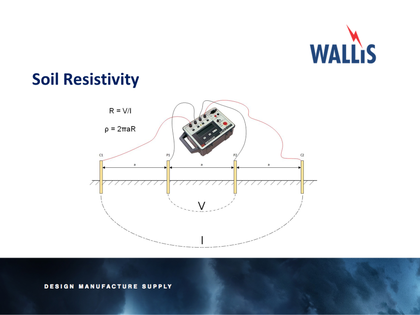
Soil Resistivity
Four probes are inserted into the ground to give a good connection. The four probes are equidistantly spaced apart from one another to the given separation distances, we tend to use the separation distances given in BS EN 50522 as a set value. The distance the probes are spaced apart, dictates the depth into the ground you are testing.
The largest separation distance would normally depend on the size of the proposed substation site, for instance a 5x5m substation may only need to have, for example a 13.5m separation distance, where as a larger substation will need larger separation distances, this would be determined by our Earthing Design professionals when attending site. We must remember that ultimately the surveys will be limited by the land available to us and can therefore take this into account should we not have sufficient space.
It may be possible to compare the derived soil model to the local geology if that is known as shown below:
| Type Of Soil | Soil Resistivity |
| Marshy Soil | 5 to 40 |
| Loam, Clay, Humus | 20 to 200 |
| Sand | 200 to 2,500 |
| Gravel | 2,000 to 3,000 |
| Weathered Rock | Mostly below 1,000 |
| Sandstone | 2,000 to 3,000 |
| Granite | Up to 50,000 |
For instance, in London, we would expect a soil model to be around 20Ω-m, as we know London is in an area of clay. If the values are dissimilar to those shown in the table extracted from BS EN 50522, we may have a problem with our surveys or the land is not natural, such as a landfill site or former quarry.
Once the first survey is complete, further surveys will be completed at different parts of the site until the data gained collates and a ‘clean’ data set is derived.
We are vigilant not to survey near buried metallic objects such as pipelines or parallel to overhead lines, as these may influence the readings taken.
Once the raw data is gained, this is then processed using the CDEGS RESAP software to gain an indicative soil model of the site and therefore completing the Soil Resistivity Survey.
Further Reading
- AN Wallis Earthing & Lightning Protection | ECA Consultant & Specifier Associate
- Earthing | An Introduction To Earthing & Earthing Designs | Part One
- Lightning | An Introduction To Lightning Protection | Networks, Strategy & Systems | Part Two
- Earth Bars | High Specification Copper Earth Bars for Lightning Protection Systems
AN Wallis
The Wallis product range includes copper earth rods (solid copper, copper bond and stainless steel types), earth bars, copper tape, earth clamps and aluminium tapes.
Specialist Distributors: LV, MV & HV Cable Jointing, Substation & Electrical Eqpt
THORNE & DERRICK are national distributors of LV, MV & HV Cable Installation, Jointing, Duct Sealing, Earthing & Electrical Equipment – we service UK and global businesses involved in cable installations, substation, overhead line and the installation of medium/high voltage cable joints and terminations at LV, 11kV, 33kV and HV.
Contact us for 3M Electrical, ABB, Alroc, AN Wallis, CATU Electrical, Cembre, Centriforce, CMP, CSD, Elastimold, Ellis Patents, Emtelle, Euromold, Filoform , Furse, Lucy Electric & Zodion, Nexans, Pfisterer, Polypipe, Prysmian, Roxtec, Sicame, WT Henley.
IET Wiring Regulations (BS 7671) | New Electrical System Designs & Installations
September 22nd, 2020 | New Electrical System Designs & Installations")
Furse BS 7671 Guide
BS 7671 18th Edition
IET Wiring Regulations
The IET Wiring Regulations (BS 7671) now require all new electrical system designs and installations, as well as alterations and additions to existing installations, to be assessed against transient overvoltage risk and, where necessary, protected using Surge Protection Devices (SPDs). Covered in the Furse BS 7671 Guide is the following:
Transient Overvoltage Protection
- What are transient overvoltages/surges?
- How are transient overvoltages created?
- The problem transients overvoltages cause
- Why surge protection is required and how to safeguard systems?
Section 443 & 534 of BS 7671 – Protection Against Overvoltage
- Risk assessment against transient overvoltages
- Compliance to BS EN 62305 & BS 7671
- Selection and installation SPDs
The IET Wiring Regulations require all new electrical system designs and installations, as well as alterations and additions to existing installations, to be assessed against transient overvoltage risk and, where necessary, protected using appropriate surge protection measures (in the form of Surge Protection Devices SPDs).
Transient overvoltage protection
Introduction
Based on the IEC 60364 series, the 18th Edition of BS 7671 Wiring regulations covers the electrical installation of buildings including the use of surge protection. The 18th Edition of BS 7671 applies to the design, erection and verification of electrical installations, and also to additions and alterations to existing installations. Existing installations that have been installed in accordance with earlier editions of BS 7671 may not comply with the 18th edition in every respect.
This does not necessarily mean that they are unsafe for continued use or require upgrading.
A key update in the 18th Edition relates to Sections 443 and 534, which concern protection of electrical and electronic systems against transient overvoltages, either as a result of atmospheric origin (lightning) or electrical switching events.
Essentially, the 18th Edition requires all new electrical system designs and installations, as well as alterations and additions to existing installations, to be assessed against transient overvoltage risk and, where necessary, protected using appropriate protection measures (in the form of SPDs).
Within BS 7671
Section 443 defines the criteria for risk assessment against transient overvoltages, considering the supply to the structure, risk factors and rated impulse voltages of equipment.
Section 534 details the selection and installation of SPDs for effective transient overvoltage protection, including SPD Type, performance and co-ordination.
Readers of this guide should be mindful of the need to protect all incoming metallic service lines against the risk of transient overvoltages. BS 7671 provides focussed guidance for the assessment and protection of electrical and electronic equipment intended to be installed on AC mains power supplies.
In order to observe the Ligntning Protection Zone LPZ concept within BS 7671 and BS EN 62305, all other incoming metallic service lines, such as data, signal and telecommunications lines, are also a potential route through which transient overvoltages to damage equipment.
As such all such lines will require appropriate SPDs. BS 7671 clearly points the reader back to BS EN 62305 and BS EN 61643 for specific guidance. This is covered extensively in the Furse guide to BS EN 62305 Protection Against Lightning.
Safeguarding your electrical systems
Why is Transient Overvoltage Protection so Important?
Transient overvoltages are short duration surges in voltage between two or more conductors (L-PE, L-N or N-PE), which can reach up to 6 kV on 230 Vac power lines, and generally result from:
- Atmospheric origin (lightning activity through resistive or inductive coupling (see Figures 02 & 03 in pdf), and/or
- Electrical switching of inductive loads
Transient overvoltages significantly damage and degrade electronic systems. Outright damage to sensitive electronic systems, such as computers etc, occurs when transient overvoltages between L-PE or N-PE exceed the withstand voltage of the electrical equipment (i.e. above 1.5 kV for Category I equipment to BS 7671 Table 443.2).
Equipment damage leads to unexpected failures and expensive downtime, or risk of fire/electric shock due to arc flash or flashover, if insulation breaks down. Degradation of electronic systems, however, begins at much lower overvoltage levels and can cause data losses, intermittent outages and shorter equipment lifetimes (see Figure 01 see pdf).
Where continuous operation of electronic systems is critical, for example in hospitals, banking and most public services, degradation must be avoided by ensuring these transient overvoltages, which occur between L-N, are limited below the impulse immunity of equipment. This can be calculated as twice the peak operating voltage of the electrical system, if unknown (i.e. approximately 715 V for 230 V systems).
Protection against transient overvoltages can be achieved through installation of a coordinated set of SPDs at appropriate points in the electrical system, in line with BS 7671 Section 534 and the guidance provided in this publication. Selecting SPDs with lower (i.e. better) voltage protection levels (UP) is a critical factor, especially where continuous usage of electronic equipment is essential.
Copper Conductors | Earth Rods | Earth Bars | Earth Bonds | Earth Clamps

Thorne & Derrick: Stockists & Suppliers of Furse Products
Thorne and Derrick are stockists and suppliers of Furse Earthing and Lightning Protection products. Acquired by the ABB Group, Furse is established as the world leader for earthing and lightning protection.
THORNE & DERRICK
Thorne & Derrick are national distributors of LV, MV & HV Cable Installation, Jointing, Substation & Electrical Equipment – servicing businesses involved in cabling, jointing, substation, earthing, overhead line and electrical construction at LV, 11kV, 33kV, 66kV and EHV. Supplying a complete range of power cable accessories to support the installation and maintenance of low/medium and high voltage power systems:
- Slip-on Cable Terminations
- Cold-shrink Cable Terminations
- Heat-shrink Cable Terminations
- Cable Joints – Heat & Cold-shrink
- Separable Connectors (Euromold)
- Surge Arresters & Switchgear/Transformer Bushings
Key Product Categories: Duct Seals | Cable Cleats | Cable Glands | Electrical Safety | Arc Flash Protection | Cable Jointing Tools | Cable Pulling | Earthing | Feeder Pillars | Cable Joints LV | Joints & Terminations MV

AN Wallis Earthing & Lightning Protection | ECA Consultant & Specifier Associate
August 17th, 2020
AN Wallis Earthing
& Lightning Protection
A. N. Wallis & Co. Ltd announce that they are formally linking up with the ECA – the UK’s leading trade association for electrotechnical and engineering services businesses.
A. N. Wallis will become an ECA Consultant & Specifier Associate, providing them with additional engagement opportunities with the trade body and its members.
Earthing and lightning protection manufactured by AN Wallis from high conductivity copper to BS EN 13601 is installed to protect buildings, overhead lines and medium/high voltage substations (MV-HV) against potentially catastrophic damage that can be caused by a lightning strike resulting in short circuiting.
The Wallis product range includes copper earth rods (solid copper, copper bond and stainless steel types), earth bars, copper tape, earth clamps and aluminium tapes.
ECA Director of Member Services Helen Atkinson commented:
“We are delighted to welcome A. N. Wallis as the ECA’s newest Consultant & Specifier Associate. We look forward to working closely with A. N. Wallis & Co. Ltd over the coming period to maximise commercial opportunities and industry collaboration.
“A. N. Wallis & Co. Ltd will now have access to an unbeatable package of resources, and the ability to further engage with the ECA’s membership base, which includes many leading electrotechnical and engineering services businesses.”
The ECA has almost 3,000 members, who undertake a range of electrotechnical design, installation, inspection, testing, monitoring and maintenance work. ECA members range from SME electrical firms to nationwide engineering services businesses, with a combined turnover of over £6 billion annually.
FURTHER READING
- Earth Tape – The Manufacture of Copper Earthing Tapes
- High Voltage Earthing & Grounding System Design Protecting Lives
- Copper Earthing Tape & Rods Protecting 33kV Substation & Transformer Bund
- Substation Earthing

Specialist Distributors: LV, MV & HV Cable Jointing, Substation & Electrical Eqpt
THORNE & DERRICK are national distributors of LV, MV & HV Cable Installation, Jointing, Duct Sealing, Earthing & Electrical Equipment – we service UK and global businesses involved in cable installations, substation, overhead line and the installation of medium/high voltage cable joints and terminations at LV, 11kV, 33kV and HV.
Contact us for 3M Electrical, ABB, Alroc, AN Wallis, CATU Electrical, Cembre, Centriforce, CMP, CSD, Elastimold, Ellis Patents, Emtelle, Euromold, Filoform , Furse, Lucy Electric & Zodion, Nexans, Pfisterer, Polypipe, Prysmian, Roxtec, Sicame, WT Henley.
High Voltage Substation Earthing Using Copper Earth Tape Conductor
May 20th, 2020![]()
A National Grid substation is a large installation where 275kV and 400kV overhead power lines or underground cables are switched and where electricity is transformed to 132kV for distribution to surrounding areas.
National Grid own HV electricity transmission network in England and Wales operating throughout Great Britain. The transmission network is made up of approximately 7,200 kilometres (4,470 miles) of overhead line, 1,400 kilometres (870 miles) of underground cable and around 330 substations.
Substations contain electrical equipment to transform the voltage to lower or higher voltages, switching equipment to connect and disconnect circuits, and protection equipment to ensure the network operates safely and reliably.
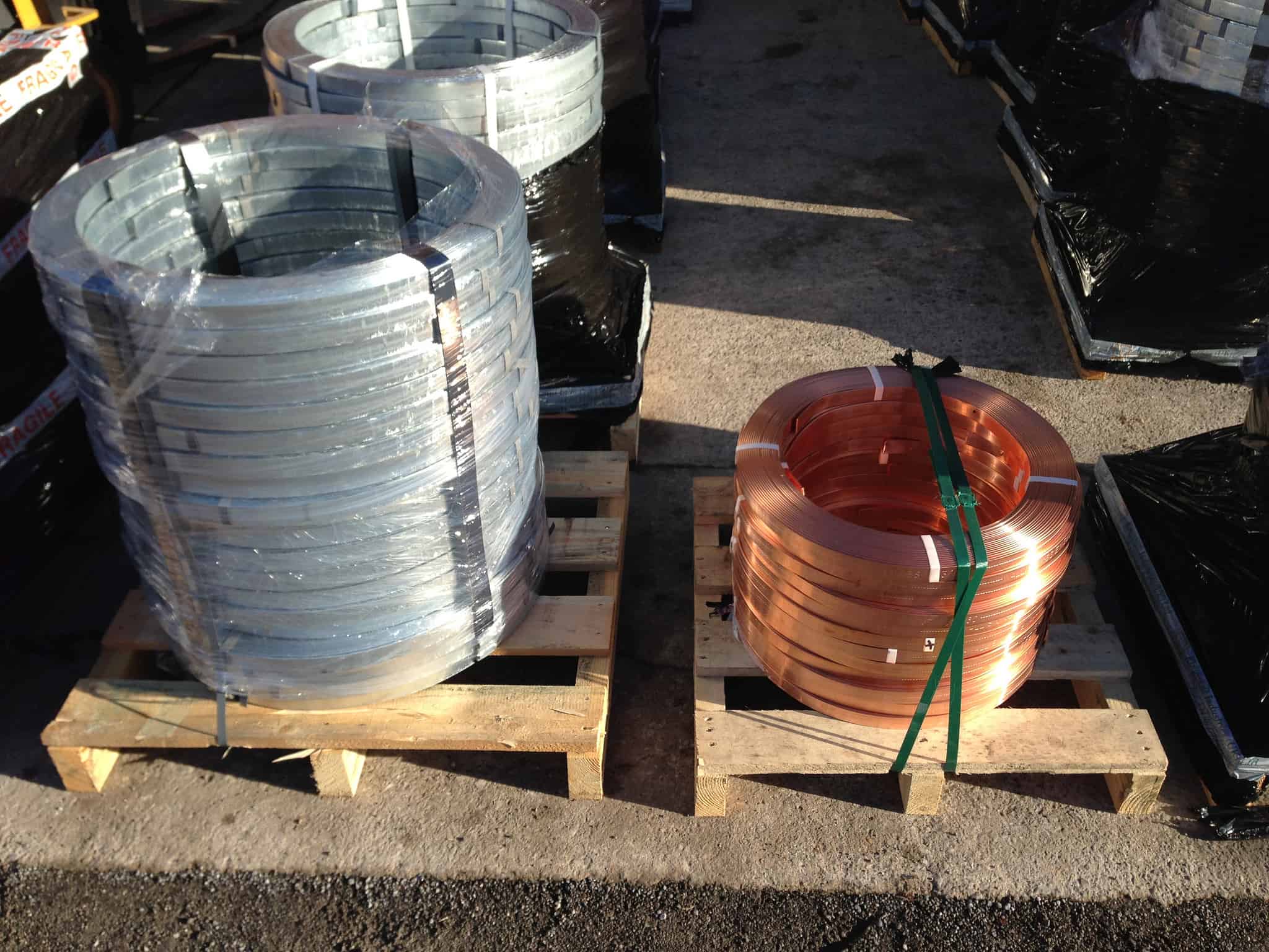
Thorne & Derrick are approved vendors to National Grid and their electricity framework contractors. We can deliver customised copper earth tape for high voltage substation earthing embossed to National Grid specification.
Bare copper earthing tape is an integral component of all high voltage substation earthing and lightning protection systems – bare copper, LSF, PVC and green/yellow insulated copper earth tapes are available.
➡ The Wallis product range includes earth rods (solid copper, copper bond and stainless steel types), earth bars, copper earth mats, earth clamps and copper earth plates.
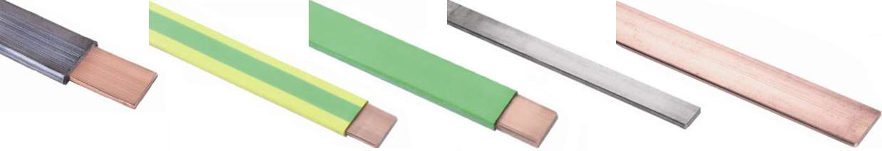
Earth Tapes – Bare & Covered Copper Tapes
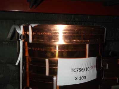
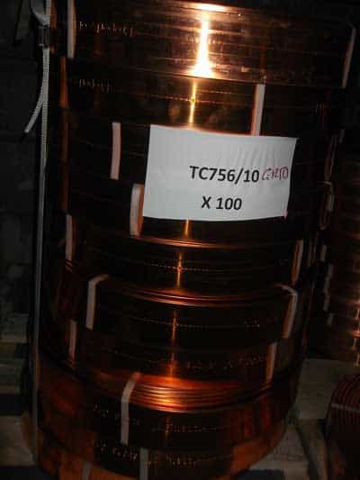
Thorne & Derrick are a leading distributor of Earthing & Lightning Protection Systems to the UK power utility industry – we can imprint or emboss copper earth tapes with all UK DNO ownership requirements.

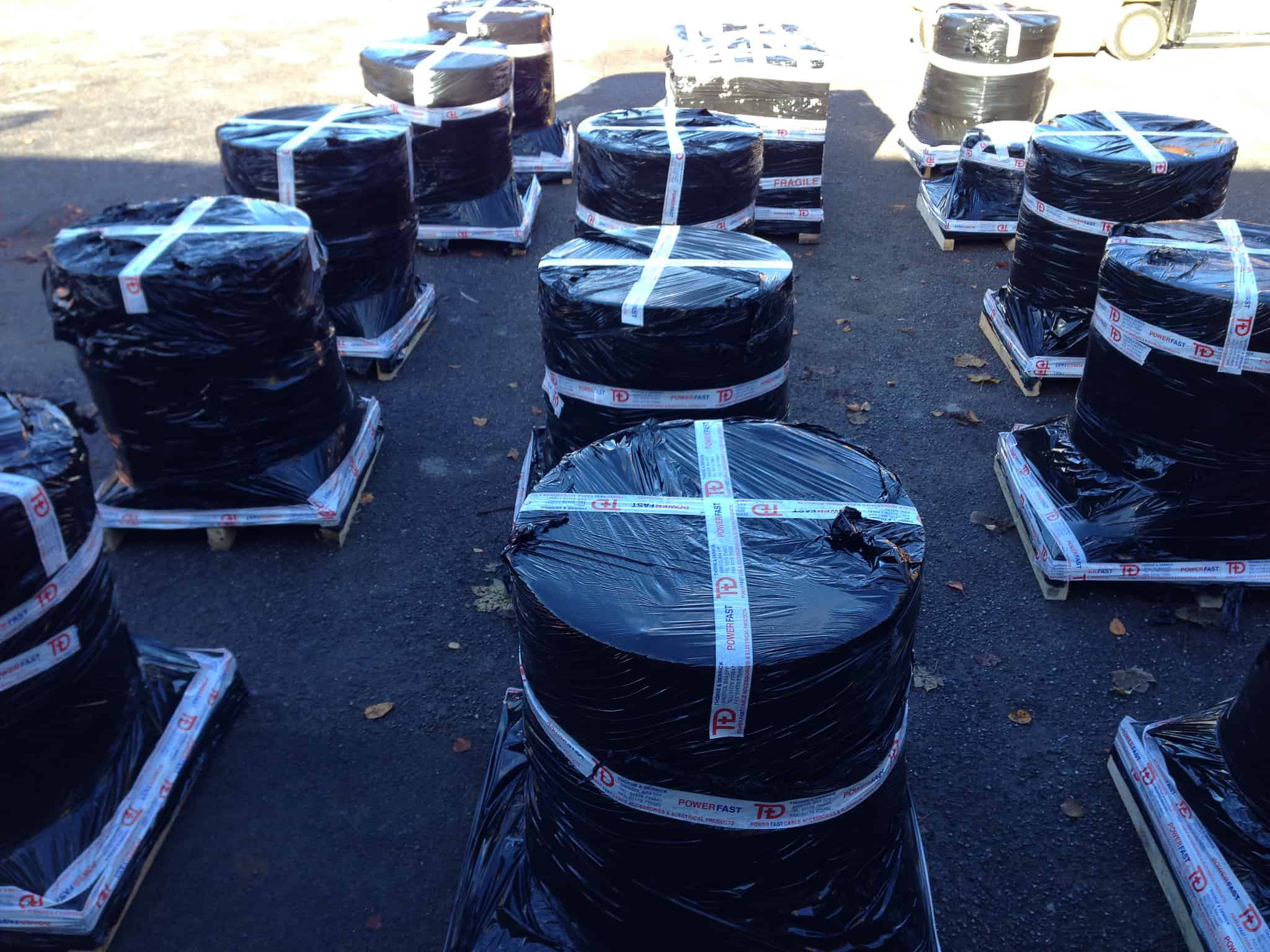
Willesden National Grid 275kV Substation
National Grid Substation Copper Earth Tape : Copper Earth Tape 75mm x 6mm embossed and stamped Property of National Grid. 1,000 metres palletised for despatch today for earthing 400kV Elstree to St John’s Wood substation maintenance projects.
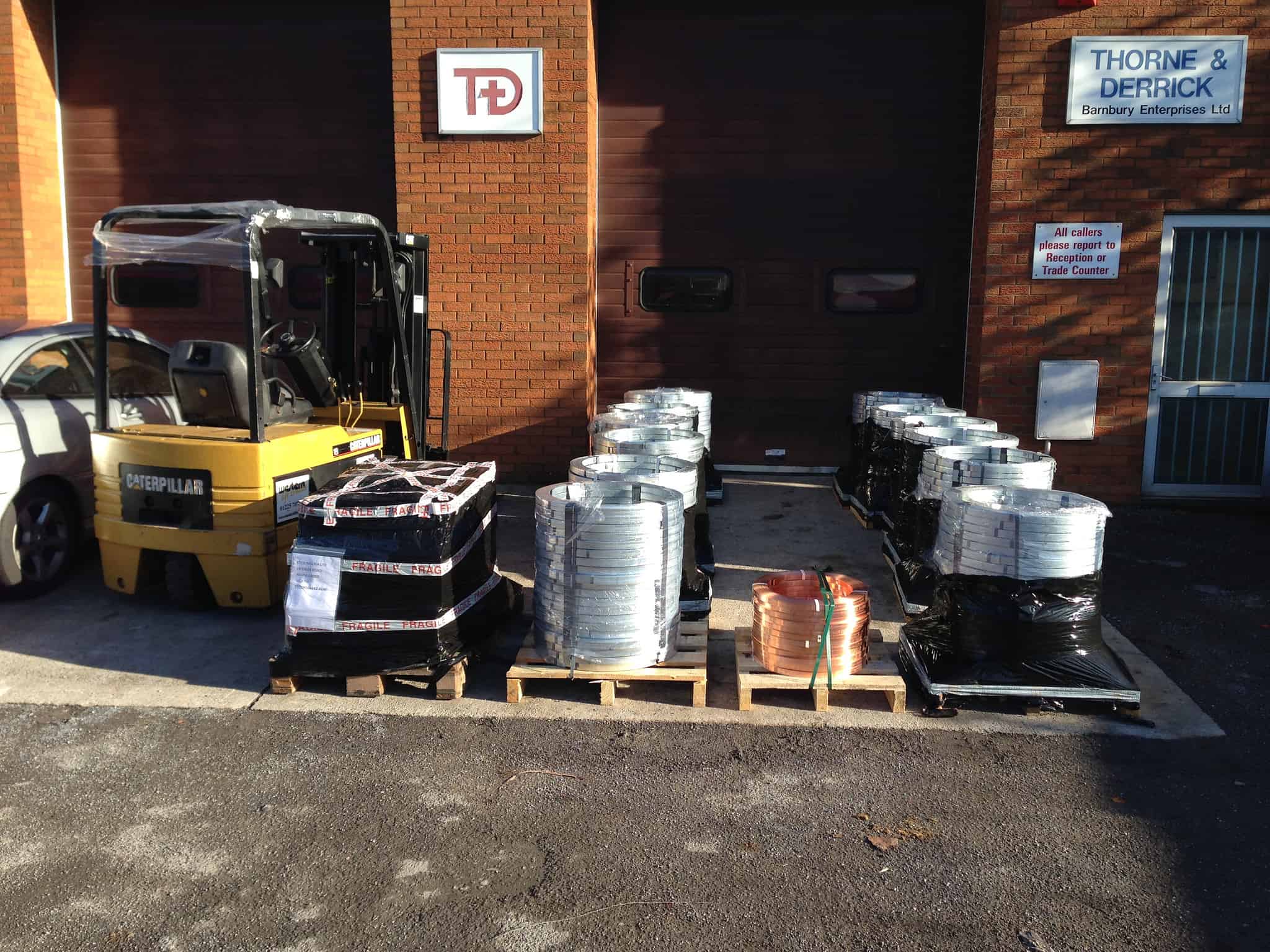
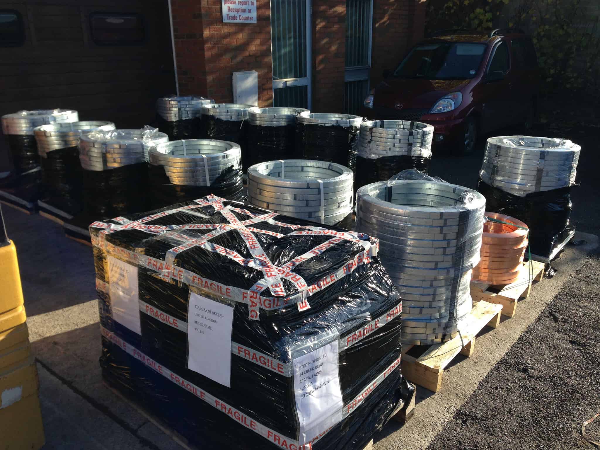
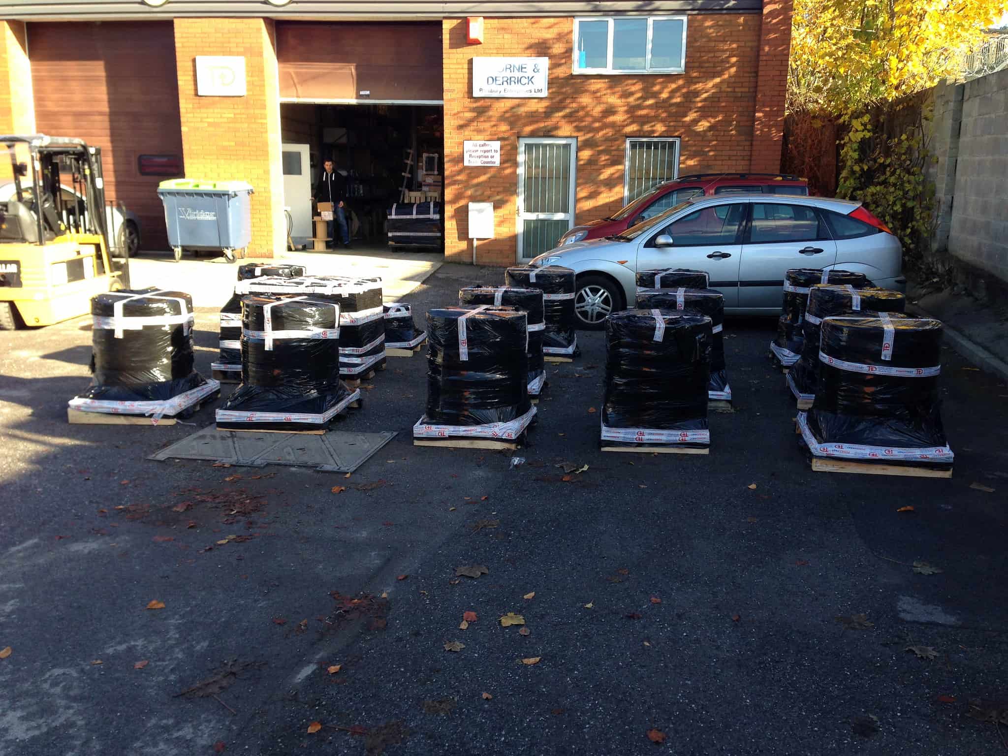
Copper Earthing & Lightning Protection – National Grid
T&D consolidated for despatch a £75K purchase order for Earthing & Lightning Protection Products – the 26 pallet consignment including galvanised steel and copper earthing tapes, mats, rods, earth bars and clamps is destined for several National Grid infrastructure projects including North London Reinforcement, London Power Tunnels & Nemo Link.
EARTHING GUIDE
Should you require further information or assistance with working on a bill of materials for your earthing requirements, please do not hesitate to contact T&D. Designers of Earthing & Lightning Protection Systems can benefit from downloading our AN Wallis Handbook – an essential resource to ensure compliance with BS EN 62305 the document covers:
- Design of Structural Lightning Protection (BS EN 62305) – Rolling Sphere, Mesh & Protective Angle
- Design of Roof Termination Network
- Copper Tape & Down Conductors – Calculation & Location
- Foundation Copper Earth Rods & Electrodes
Further Reading
Underground Cable Photo Album 1890-1940 – Western Power Distribution (WPD)
Specialist Distributors: LV, MV & HV Cable Jointing, Substation & Electrical Eqpt
THORNE & DERRICK are national distributors of LV, MV & HV Cable Installation, Jointing, Duct Sealing, Earthing & Electrical Equipment – we service UK and global businesses involved in cable installations, cable jointing, substation, overhead line and electrical construction at LV, 11kV, 33kV and EHV.
Contact us for 3M Electrical, ABB, Alroc, AN Wallis, CATU Electrical, Cembre, Centriforce, CMP, CSD, Elastimold, Ellis Patents, Emtelle, Euromold, Filoform , Furse, Lucy Electric & Zodion, Nexans, Pfisterer, Polypipe, Prysmian, Roxtec, Sicame, WT Henley.
