Ellis Patents Colossus Trefoil Cable Cleats (24-170mm)

Cable Cleats
Colossus Cable Cleats
Trefoil Cleats
- Maximum Short Circuit Test Level 104kA
- Cable Cleat Spacing – 7800mm with intermediate straps every 1300mm
- Cable Cleat Type – Trefoil Cables
- Material – Olymer Frame + Stainless Steel Strap
- Cleat Range Trefoil Cables – 24-170mm
Thorne & Derrick International, based in the UK, stock and distribute the complete range of cable cleats and cable hangers manufactured by Ellis Patents including the Colossus range for short circuit retention and cable protection of LV (Low Voltage), MV (Medium Voltage) and HV (High Voltage) power cable systems in single-way or trefoil installation.
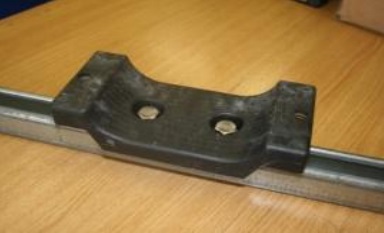
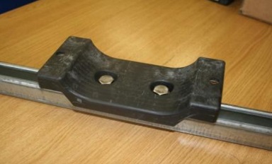
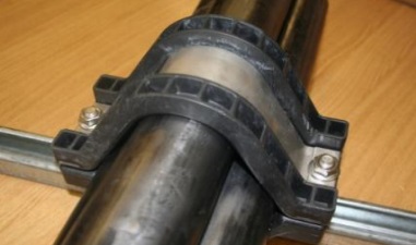
Ellis Patents Colossus Cable Cleats are stainless steel trefoil cable cleats for cable diameters ranging from 24-170mm for cable applications where the highest level of short circuit withstand and protection is required. The cable cleats have the uniquely designed LSF polymer frame.
Colossus cable cleats are able to withstand moderate levels of short-circuit and are available in a range of sizes that are suitable for trefoil cables up to 170mm in diameter.
The Colossus cleats are able to provide a more suited support solution for larger cable sizes and the polymer frame provides further protection to the cables during short circuit conditions.
It is recommended that the cable cleats use either 10mm or 12mm bolts that can be bought separately.
International Standard IEC 61914:2009
Ellis Patent cable cleats with international specifications are used to clamp and retain LV MV HV cables including 11kV and 33kV networks depending on short-circuit calculations according to IEC61914 calculations.
For cable installations where corrosion protection is required, including onshore and offshore substations or hazardous area locations, see our complete range of  stainless steel cable cleats.
ELLIS PATENTS Colussus CABLE CLEATS
Maximum Short Circuit Test Level Cleat Spacing
- 104kA every 7800mm with intermediate straps every 1300mm

Ellis Patents Colossus Trefoil Cable Cleats (24-170mm)
INSTALLING CABLE CLEATS
Installation instructions for trefoil cables using Colossus cleats manufactured by Ellis Patents:
 |
 |
 |
 |
 |
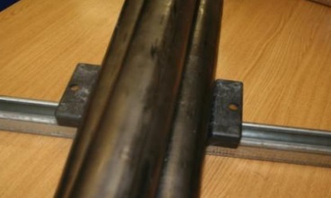
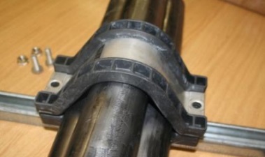
| 1.Remove the closing flange nuts and set screws. | 2. Fix the bottom half of the cleat to the support structure using M10 or M12 fixings as appropriate. | 3. Lay the LV MV HV cables in place. | 4. Fit the top half of the cleat over the cables. Secure with the M12 setscrews and flange nuts (19mm spanner/socket for setscrews, 16mm spanner/socket for flange nuts). |
5. Important. Do not over tighten the cleat. The liner should be in contact with the cable but does not need to be so tight that the cable bulges at either side of the cleat liner. |
ELLIS PATENTS Colossus CABLE CLEAT TESTING INFORMATION
Should you require test samples or further specification details about Colossus cable cleats please contact us:
| Properties | IEC 61914:2009 Classification Clause | Units / Classification | Colossus Trefoil Cable Cleat Application Test Data |
| Cleat Type | 6.1, 6.1.3 | Composite | – |
| Impact Resistance | 6.3, 6.3.5, 9.2 | Very Heavy Classification (5kg @ 400mm) | Pass |
| Resistance to Electromechanical Force (undertaken at ZKU Laboratories CZ) | 6.4, 6.4.3, 9.5 | 104kA @ 7.8m (with intermediate straps every 1.3m centres M12 Fixings (withstanding two short circuits) | Refer to Ellis Patents for test certificate |
| Temperature for Permanent Application | 6.2 | ºC | -40 to +60 |
| Needle Flame Test | 10.0, 10.1 | Application Time (seconds) | > 120 |
| Lateral Load Test | 9.3 | Newtons (N) | 14,000 |
| Axial Movement Test | 9.4 | Newtons (N) | Refer to Ellis Patents for details |
Colossus CABLE CLEAT – Trefoil CABLE APPLICATION SELECTION TABLE
The following selection table provides information to enable the specification or purchase of the correct Colossus cable cleat manufactured by Ellis Patents – contact Thorne & Derrick for further technical information, installation advice, samples or to place an order.
| Colossus Trefoil Cable Cleat Part Number | Cable Range | Dimensions | Weight (g) | |||||
| Min Dia (mm) | Max Dia (mm) | W (mm) | H (mm) | D (mm) | P (mm) | Ø Fixing Holes | ||
| COL24-29 | 24 | 29 | 128 | 87 | 60 | 25 | 2 x M10 + M12 | 604 |
| COL27-32 | 27 | 32 | 133 | 92 | 60 | 25 | 2 x M10 + M12 | 623 |
| COL30-36 | 30 | 36 | 137 | 101 | 60 | 25 | 2 x M10 + M12 | 639 |
| COL34-41 | 34 | 41 | 146 | 110 | 60 | 25 | 2 x M10 + M12 | 690 |
| COL39-47 | 39 | 47 | 157 | 122 | 60 | 25 | 2 x M10 + M12 | 734 |
| COL45-54 | 45 | 54 | 171 | 141 | 70 | 50 | 2 x M10 | 913 |
| COL52-62 | 52 | 62 | 185 | 156 | 70 | 50 | 2 x M10 | 974 |
| COL60-72 | 60 | 72 | 204 | 176 | 70 | 50 | 2 x M10 | 1063 |
| COL69-83 | 69 | 83 | 225 | 202 | 100 | 75 | 2 x M12 | 1590 |
| COL79-95 | 79 | 95 | 247 | 225 | 100 | 75 | 2 x M12 | 1700 |
| COL91-109 | 91 | 109 | 273 | 253 | 100 | 120 | 2 x M12 | 1900 |
| COL105-126 | 105 | 126 | 306 | 286 | 150 | 120 | 2 x M12 | 3030 |
| COL122-146 | 122 | 146 | 345 | 324 | 150 | 150 | 2 x M12 | 3270 |
| COL-142-170 | 142 | 170 | 371 | 371 | 150 | 150 | 2 x M12 | 3680 |
Saddled Colossus CABLE CLEAT – Trefoil CABLE APPLICATION SELECTION TABLE
The following selection table provides information to enable the specification or purchase of the correct cable cleat – contact Thorne & Derrick for further technical information, installation advice, samples or to place an order.
| Colossus Trefoil Cable Cleat Part Number | Cable Range | Dimensions | Weight (g) | |||||
| Min Dia (mm) | Max Dia (mm) | W (mm) | H (mm) | D (mm) | P (mm) | Ø Fixing Holes | ||
| COL69-83SC | 69 | 83 | 225 | 202 | 300 | 75 | 2 x M12 | TBA |
| COL79-95SC | 79 | 95 | 247 | 225 | 300 | 75 | 2 x M12 | TBA |
| COL91-109SC | 91 | 109 | 273 | 253 | 300 | 120 | 2 x M12 | TBA |
| COL105-126SC | 105 | 126 | 306 | 286 | 300 | 120 | 2 x M12 | 3400 |
| COL122-146SC | 122 | 146 | 345 | 324 | 300 | 150 | 2 x M12 | TBA |
| COL142-170SC | 142 | 170 | 390 | 371 | 300 | 150 | 2 x M12 | TBA |

Ellis Patents Colossus Trefoil Cable Cleats (24-170mm) – Dimensions

Cable Cleats v Cable Ties
The Video produced by Ellis Patents provides compelling evidence of the need to ensure all cables are adequately supported and retained to cable containment to protect against the devastating effects of short circuit faults: 118kA Short Circuit Fault Current | 0.1 Seconds Duration | 480V Low Voltage Cables.

Cable Lugs | Cable Glands | Feeder Pillars | Cable Joints LV | Joints & Terminations MV HV 11kV 33kV