Unlocking The Power Of Solar | Electrical Balance of System in Solar Applications
Electrical Balance of System in Solar Applications
The hard parts are done. You have a solar farm site ready to build and an order placed for high performance PV modules, best-in-class inverters, and a tracking system to maximise energy production. Now you just need to figure out how to get it all connected.
Easy, right?
It’s not rocket science, but thoughtful selection of Electrical Balance of System (EBOS) components is essential for project success. In a recent audit from Solargrade, 62% of all utility-scale solar projects had critical safety issues, 91% of which related to direct current (DC) power distribution. Most issues were caused by field-made connectors and wire management, components of the EBOS.
To understand where to focus to create a reliable, high-performance EBOS, let us start with the PV module and work our way to the DC/AC inverters that connect to the grid.
➡ Thorne & Derrick partner with Panduit to bring the most innovative renewable energies solutions to the market.
Below discover how Panduit is at the forefront of accelerating solar projects, enhancing reliability, and increasing profitability with our expert insights on navigating Electrical Balance of System (EBOS).
Join us as we unlock the potential of solar energy for reliable, efficient projects.
Electrical Balance of System Components IN THE SOLAR iNDUSTRY
PV modules range in size and power output, but all have DC wires exiting from a junction box on the back. In a solar array, these wires are routed as a bundle or spliced together at prescribed intervals and fed into a combiner box. The combiner box, as its name suggests, combines the power from these strings of modules so that a pair of larger, high-voltage cables can carry their combined power in a “home run” to the inverter and then eventually on to the grid.
Commercial and utility scale solar projects necessarily have a large footprint to produce the amount of required power. Because each PV module only creates 400–600 W, you need 1,667–2,500 modules to produce just one megawatt (MW) of electricity, and utility projects can typically range anywhere from 20 to 500+ MW. With all that scale comes a huge amount of cable to manage. And because these projects are placed in areas with intense sun, all the components are exposed to the elements. To be reliable, solar cable management solutions must securely hold cables in high wind, protect from long-term abrasion, withstand harsh UV, potential chemical exposure, and extreme temperatures.
Several suitable options exist for routing smaller cables along the back of PV modules. The most common include dedicated solar clips that snap on the metal frame, specialised wire hangers that fit through holes in the frame, and heavy-duty cable ties. Arrays that move to track the sun create some additional challenges with abrasion, so flexible corrugated tubing is often used to surround cables and protect around potential pinch points.
At each combiner box, dozens of smaller cables enter and connect to a pair of busbar conductors, most commonly with power lugs. The lugs are crimped using tools or mechanically terminated to the ends of the wires and secured to the busbar with screws to ensure reliability and efficiency.
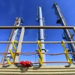
Power exits the combiner box through higher-voltage cables and is routed one of two ways: either below ground in a trench or suspended in bundles from steel cables strung in-between rows. These higher voltage “home run” cables carry power to an inverter connected to the grid, or directly to DC battery storage on site.
As with any electrical system, proper bonding and grounding are critical parts of a solar project. Grounding provides a super-low-resistance path for electricity to flow, so that power can safely complete a circuit should a fault occur.
In the EBOS, bonding components like lugs and straps connect each of the individual array components together and then to the grounding system. Without proper grounding, tray and racking surfaces can become energised in the event of a fault, creating a life-threatening situation for people working on the solar array.
Most solar safety and reliability issues emerge from mistakes in managing DC wiring and grounding. Selecting appropriate cable management, termination, and grounding solutions can prevent some challenges. Placing an emphasis on ease of installation, quality materials, and long-term reliability when specifying EBOS components will minimise problems once the project is built.
Maximising Return on Investment Through EBOS
Like any utility, the goal of solar farms is to produce the most usable energy at the lowest total cost over the life of the project. To optimise long-term return on investment, it’s important to consider ease of installation, durability, and safety when selecting BOS components.
Finding skilled labour continues to be a challenge in the construction industry, and the labour needed to connect 2,500 PV modules is significant, let alone 2.5 million. EBOS solutions that simplify installation and minimise re-work can noticeably reduce labour hours and total installation costs. Even components that save seconds per operation compound to significant time savings over the duration of the build.
Once a power plant is commissioned, any downtime directly impacts profitability. Because these projects necessarily involve hundreds of thousands of individual modules, any weaknesses in components will be exposed and magnified. Selecting products specifically designed to last years in harsh environments reduces unplanned maintenance costs and lowers the total cost of ownership over the life of the project.
Solar projects typically have a usable lifespan of 25+ years. To maintain the highest level of production, it’s necessary to perform regular maintenance, which includes everything from cleaning modules and controlling vegetation to replacing deteriorating components.
Effective labelling of all system components during installation is critical for future operations personnel to interact with equipment safely and efficiently. Exposure to UV and precipitation can lead to fading and make labels illegible, so high-quality, easy-to-read solutions designed for outdoor environments are a good investment to ensure efficient maintenance in the future.
Summary
Though EBOS components (excluding wire) represent less than 5% of total project costs, they can be an important way to control costs and optimise performance throughout the life of a solar installation. Quality components maximise labour efficiency during the initial build and result in fewer errors that require re-work. Using longer lasting environment-specific materials and easy-to-read labelling solutions simplifies future operations and reduces maintenance costs. And most importantly, getting EBOS right addresses the most common critical safety issues found in solar projects today.
Experienced Brand Marketer with a specialization in strategy, content marketing, product marketing, storytelling, public relations, event management, athlete and ambassador partnerships, advertising, and team leadership.
Andrew is a member of the Panduit Renewable Energy team as a Product Marketing Manager. He is passionate about building an electrified future and the technology powering energy transformation.
Panduit Electrical Group is a world wide leader in the manufacture of high-quality electrical products including cable ties, wiring accessories, terminals, and identification products such as computer printable labels and portable labelling systems, wiring duct, heat shrink tubing, wire abrasion protection, and accessories.
Thorne & Derrick are Specialist Distributors to Solar EPC’s & High Voltage Jointing Contractors working on the design, construction and maintenance of UK, European and international projects supplying an extensive range of LV HV Solar Cables, Jointing, Substation & Electrical Eqpt.Based in the UK, we are highly customer responsive and absolutely committed to providing a world-class service.
We stock LV HV Solar Cables, Accessories & Electrical Equipment to enable the construction, maintenance and operation of utility-scale PV installations – our products connect600V/1500V solar cablesinto combiner boxes, inverters, transformers and energise switchgear up to 33kV/132kV for high voltage grid connections.
Since 1985, we have provided expert technical support and express delivery from extensive UK stocks to world-wide destinations.
We look forward to working to with you on your next Solar project.
Authored by Pieter Pijnenburg | Arc Flash Engineer from Leaf Electrical Safety
Electrical Safety
Any industrial or commercial workplace requires arc flash and electrical safety training, and it is essential in order to make sure your staff members know what they need to do to remain safe.
Leaf Electrical Safety is an electrical safety company that can provide expert advice on electrical safety to help teams build processes and improve safety culture. Working primarily across Canada and the USA, they help solve your industrial electrical safety problems.
Electrical safety compliance training should keep you on the edge of your seat, wanting more, because it will highlight the dangers that your team faces on a daily basis. Special thanks to Jon Travis for the kind permission to republish.
In our ever-changing renewable world, the safety of personnel is still and should remain a paramount concern. Wind Energy Conversion Systems (WECS) are some of the more prominent types of renewable generation whose safety concerns are exacerbated by two main factors:
Remoteness: due to the nature of wind turbines being remote and/or offshore, any hospitalisation can turn into a race against time.
Confined spaces: the electrical components and work areas within a wind turbine are typically in confined spaces, which becomes more problematic when you add multiple workers into the mix.
WHAT ARE THE ELECTRICAL SAFETY HAZARDS
IN WIND TURBINES?
In order to mitigate hazards and allow for adequate protection, WECS equipment and operators should be adequately equipped to deal with the following main hazards issues that commonly occur in WECS:
Arc Flash
Shock
Overloaded Circuits
Defective Insulation
Wet Environment
Damaged or Worn Equipment
ARC FLASH RISK IN WIND TURBINE
Potential arc flashes in WECS are potentially life-threatening issues which require detailed analysis and physical protection to be accounted for. Arc flash hazard analysis (incident energy calculations) is typically used and utilises standards such as IEEE 1584-2018 to perform the calculation. Once the calculation is made and the proper arc flash boundaries are determined, personal protective equipment (PPE) can be assigned based on the calculations (see CSA Z462 for more details).
SHOCK RISK IN A WIND TURBINE
Shock risk, like an arc flash, is a potentially life-threatening hazard if not properly accounted for. Usually, a shock risk assessment is performed to look at key system parameters such as voltage level, shock boundary, environment, equipment type, and condition.
OVERLOADED CIRCUITS
Overloaded circuits can cause various problems and increase the risks of shock and arc flash considerably if not protected and isolated properly. Preventative measures can be taken through routine inspection of protection devices and physical circuitry (with proper PPE) to check for any abnormalities in the equipment.
DEFECTIVE INSULATION
Defective insulation can cause system malfunction and exponentially increase the potential arc flash and shock risks. Regular insulation resistance (IR) tests, whose procedure for electric machinery is highlighted in IEEE 43-2013, should be performed to test the dielectric strength of the insulation.
WET ENVIRONMENT
Wet surfaces can prove hazardous to people as well as electrical equipment. In order to reduce these potential hazards, regular equipment checks should be carried out on the exterior and interior of the WECS for potential water seepage/damage.
DAMAGED OR WORN EQUIPMENT
Equipment can be compromised from its normal working state for a variety of reasons, but compromised equipment can cause major problems if it is not repaired or replaced quickly enough. To mitigate this, scheduled maintenance procedures should be made and followed (see CSA Z463).
ELECTRICAL SAFETY PRECAUTIONS FOR WIND TURBINE WORKERS
PROPER PERSONAL PROTECTION EQUIPMENT
Each hazard risk category requires a different level of protection. Categories range from 1 to 5 as defined within CSA Z462 and laid out below as follows:
PPE category
1
2
3
4
5
Incident Energy
Up to 4 cal/cm²
Up to 8 cal/cm²
Up to 25 cal/cm²
Up to 40 cal/cm²
Up to 75 cal/cm²
Figure 1:PPE category as defined by CSA Z462
ARC FLASH BOUNDARY
An arc flash boundary is the shortest distance at which a person working at the time of an arc-flash incident may receive an onset of a second-degree burn or worse (1.2 cal/cm2) if not adequately protected by flame-resistant (FR) clothing.
LABELING
Labelling is defined in CSA 22.1-18 for both small (64-300) and large (64-400) wind turbines as “a permanent marking” that must be created near an easily accessible location near the disconnecting for the wind turbine output circuit (64-300) or base of the tower (64-400) and display the following critical information:
Overcurrent protection values provided by the wind turbine for the stator and rotor, if applicable;
Short-circuit current rating (SCCR);
A brief system description, including the type of generator (synchronous or induction);
Rated output current; and
Rated output voltage at the grid connection to the turbine.
Warning notice (large turbines only)
Furthermore, arc flash and shock hazard labels should be provided for large wind systems. These labels are covered in CSA Z462 Annex Q, which highlights procedures for labelling arc flash hazards and shock protection. The minimum arc flash label requirement per CSA 22.1-18 (Canadian Electrical Code Part 1) is:
Figure 2:CSA Arc Flash label template for CSA 22.1 Requirements
Whereas the CSA Z462 recommends that the label look something more like:
Like any generator, the WECS should be properly grounded and follow CSA standards and IEEE 142. Proper grounding of turbines follows the general ruleset of AC connections as defined by CSA 22.1 Section 64-312 as:
1) Exposed non-current-carrying metal parts of towers, turbine nacelles, other metallic equipment, and insulated conductor enclosures shall be bonded to ground in accordance regardless of voltage.
2) Metallic towers or supporting structures shall be bonded to the ground with a minimum No. 6 AWG.
3) Guy wires used to support turbine towers need not be grounded.
4) Towers or structures shall be grounded by means of grounding electrodes to limit voltages imposed by lightning.
5) Notwithstanding Subrule 4), metal towers located on steel-supported buildings shall be bonded to non-current-carrying metal parts of the building.
FAULT FINDING & TESTING
To effectively find faults in a WECS, proper fault monitoring relay devices should be installed particularly:
50 – Instantaneous Overcurrent Relay
51 – AC Time Overcurrent Relay
59 – Overvoltage Relay
These devices will be able to monitor and indicate the levels of key parameters such as voltage and current.
ELECTRICAL SAFETY STANDARDS AND TRAINING REQUIREMENTS FOR THE WIND ENERGY INDUSTRY
CSA 22.1-2018 lists several safety requirements for both small and large wind turbines (64-300 tot 64-414), including marking, maximum voltage, insulated conductors, wiring methods, overcurrent protection, disconnecting means, grounding and bonding, maintenance receptacles, lightning protection, surge protection and system demarcation (large turbine).
Training requirements are highlighted in Annex U of CSA Z462, which highlights procedures for human performance in electrical safety. It highlights risk control methodologies and procedures for human performance, such as
Thorne & Derrick protect substation engineers, asset managers, SAPS, cable jointers, overhead linesmen and utility workers with PPE and safety equipment: this includes insulating gloves, arc flash clothing, voltage detectors, insulating mattingand portable earthing to ensure worker safety when carrying out repair and maintenance on LV-HV switchgear, transformers, substations and turbines.
All of our Cable Connection & Energisation Accessories including Medium & High Voltage joints, terminations, connectors and cleats are tested to the latest international standards and supporting ranges of professional installation tools are stocked to reduce incident, accident and downtime to plant and people.
Use of Pfisterer KP-Test 5HL Live Line Testers & Indicators
Voltage Detectors Distributed from Stock | Approved Supplier | UK & Export Sales
Pfisterer Voltage Detectors
Pfisterer KP-Test 5HL is a capacitive voltage detector—the universal Medium & High Voltage Detection & Live Line Tester (LLT) product range for nominal voltages from 110kV to 220kV. The voltage detector presents the operating voltage when brought into contact with the MV HV overhead lines and conductors.
The Pfisterer KP-Test 5HL voltage detector provides a high level of user-friendliness and user safety – KP-Test 5HL is designed and type-tested to Standard IEC 61243-1.
Other versions of the HV high voltage detector with deviating voltages, ranges of nominal voltages, frequencies, and languages are available on request.
KP-Test 5 range of instruments from Pfisterer can detect voltage level 1 to 420 kV AC.
Pfisterer KP-Test 5HL
KP-Test 5HL Live Line Indicators
The KP-Test 5HL is one of several certified live line indicators (LLI’s) that have been used to test 25kV conductors to ensure that they have been disconnected from the power source prior to connecting to earth or testing before touching. LLIs are safety devices on which human lives may depend. These should be handled with extreme caution and protected against damage.
To discharge any induced voltages, field equipment earthing, also known as portable earthing, may be necessary when employing voltage detectors to determine whether operating voltages are present on MV-HV power cables or overhead lines. This is because the equipment may be operating close to live conductors.
KP-Test 5HL is limited to use on the lowest conductor of the objects being tested, such as the bottom autotransformer feeder (ATF) or contact wire. Only those with a valid competency (authorised person or nominated person) and who have attended a familiarisation briefing should use it.
Voltage Detector Part Number
Nominal Voltage (kV)
Nominal Frequency (Hz)
Diameter of hook (mm)
KP-Test 5HL
110-220
50
70
Benefits of using Voltage Detectors
Furthermore, voltage detectors are crucial instruments made to improve electrical safety in a range of settings. These tools are essential for averting mishaps, lowering the risk of casualties, and safeguarding infrastructure. An extended explanation of the features stated is provided below:
Weather Resistance: They are designed to withstand various environmental conditions, including rain. This allows operators to use them in diverse weather conditions without compromising their functionality. This feature ensures that the detectors remain operational even when exposed to rain, providing continuous safety in outdoor settings.
Personnel Safety:Voltage detectors significantly reduce the risk of serious injury to personnel working with electrical systems. Their ability to detect live voltage without physical contact ensures that operators can assess the presence of electrical energy safely. This minimizes the chances of electrical accidents, protecting personnel from electric shocks and other potential hazards associated with working in proximity to live electrical components.
Infrastructure Protection: Voltage detectors play a vital role in safeguarding electrical infrastructure. By providing a means to detect live electrical components, they help prevent accidental damage to critical equipment and wiring. This protection extends the lifespan of electrical systems, reduces the frequency of repairs, and contributes to the overall reliability of the infrastructure.
Quick Drying:After being exposed to rain or wet conditions, voltage detectors are designed to dry quickly once not in use. This feature is essential for maintaining the reliability of the device. The rapid drying capability ensures that the detector can be stored or reused promptly after exposure to moisture, minimizing downtime and allowing for efficient use in dynamic work environments.
THORNE & DERRICK
Thorne & Derrick stock and distribute PFISTERER CONNEX Connectorsfor medium / high voltage cable connection and termination to electrical systems up to 33kV – we provide competitive prices for PFISTERER CONNEX connectors used to terminate and connect polymeric insulated MV-HV cables into gas insulated switchgear and electrical equipment from extensive UK stocks.
Thorne & Derrick are national distributors of LV, MV & HV Cable Installation, Jointing, Substation & Electrical Equipment – servicing businesses involved in cabling, jointing, substation, earthing, overhead line and electrical construction at LV, 11kV, 33kV, 66kV and EHV. Supplying a complete range of power cable accessories to support the installation and maintenance of low/medium and high voltage cable systems:
Slip-on Cable Terminations
Cold-shrink Cable Terminations
Heat-shrink Cable Terminations
Cable Joints – Heat & Cold-shrink
Separable Connectors (Euromold)
Surge Arresters & Switchgear/Transformer Bushings
Voltage Detectors | Phase Comparators | Insulating Poles | Portable Earthing | LV MV HV
Guest Article : Authored by Ryan Smith MSc MIET | Owner of EasyCableSizing.com
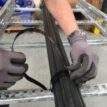
As an Electrical Engineer, I’ve always been fascinated by the “hows and whys” in the design and engineering of power cables. In this Article, I delve into the essential aspects from the core components of a power cable to the considerations in choosing the right materials.
Key highlights include:
the critical roles of conductors, insulation, and sheathing
a comparative look at copper and aluminium in cable applications
insights into the evolving world of eco-friendly materials in cable design
importance of understanding electrical properties like conductance, resistance, capacitance, and inductance
I also discuss the significance of standards like IEC 60287 and IEC 60502 in cable sizing, essential for anyone working with MV and HV power cables. Whether you’re a fellow engineer, a student, or just curious about the field, I believe there’s something valuable for everyone in this piece.
Cable engineering is a specialised domain focusing on the design, implementation, and optimisation of electrical power cables. This field encompasses a range of activities from material selection to performance testing, ensuring that cables meet the demands of modern electrical networks.
Cable construction Basics
Core components of A POWER CABLE
Underground power cables consist of a minimum of two components, a conductor and insulation, however these are usually accompanied by other elements, each playing a critical role in overall functionality:
cONDUCTORS
Conductors are the principal element of a power cables, responsible for transmitting electricity. They are typically made of materials like copper or aluminium, chosen for their excellent conductivity and durability. In other applications where conductors are required, other materials are often used, like gold, but these aren’t feasible for power applications due to their high cost.
iNSULATION
Insulation in power cables primarily provides segregation from a conductor and other conductive materials, whether they’re intended to be conductors or not, but also protects it from environmental factors.
Sheathing and Jacketing
Sheathing and jacketing provide an additional layer of protection to cables, safeguarding against physical damage and environmental factors. This layer is crucial for cable longevity and reliability.
Types of Power Cables
Power cables are categorised based on their voltage capacity:
Low voltage Cables
Low voltage cables are designed for applications with voltage requirements commonly up to 1000V. They are commonly used in residential and commercial settings for everyday electrical needs, and in industrial settings for smaller loads. Learn more about low voltage, heavy-duty industrial cables like the H07RN‑F rubber cable in our detailed selection guide.
Medium and High Voltage Cables
Medium and high voltage cables cater to more demanding applications, such as industrial plants, generation, and power transmission lines. They are able to handle higher voltages and are key in large-scale power distribution.
Material Selection in cable design
Conductive materials: Copper vs. aluminium
The two main materials used for conductors are copper and aluminium, due to their wide availability and relatively low cost.
Copper, known for its superior conductivity and durability, is often preferred for certain applications, despite its higher cost.
Aluminium, being lighter and more cost-effective, is a viable alternative, especially for large-scale power transmission.
Insulation Materials: XLPE, PVC, and Others
Different insulation materials like XLPE, PVC, and EPR play a crucial role in cable performance:
XLPE (Cross-Linked Polyethylene): Known for high temperature resistance and excellent electrical properties, ideal for high voltage applications.
PVC (Polyvinyl Chloride): Offers flexibility and durability, used in a wide range of cable types.
EPR (Ethylene Propylene Rubber): Notable for dielectric strength, flexibility, thermal stability, suitable for high stress environments.
Others: Includes materials like Teflon and Rubber, chosen for specific applications based on properties like fire resistance, low toxicity, or extreme environmental conditions.
Advances in Eco-friendly Materials
The cable industry is evolving towards eco-friendly materials like polypropylene (PP) to minimize environmental impact. PP stands out for its excellent insulating properties and recyclability, making it a promising material for next-generation power cables. However, its application in cable insulation still faces challenges, such as optimising its mechanical and electrical properties. This drive towards sustainable materials is redefining cable technology, balancing environmental considerations with performance requirements. For an in-depth understanding, read more about the potential of PP in power cable insulation in this research article.
Electrical properties of cables
Conductance and resistance
Understanding the conductance (G)and resistance ®of power cables is essential for evaluating their performance. These properties are inversely related, where G=1⁄R. Conductance represents a cable’s ability to allow electric current flow, while resistance quantifies the opposition to current flow. This affects cable efficiency, with lower resistance implying less energy loss as heat. Factors such as material type, cross-sectional area, and temperature influence these properties.
Impedance (Z) in cables, a combination of resistance, inductance, and capacitance, is crucial in AC power systems. It can be represented as Z=√R²+(XL−XC)², where XL is the inductive reactance and XC the capacitive reactance. Impedance affects signal quality and power loss in cables, and its proper management is vital for maintaining the integrity and efficiency of electrical systems.
For an in-depth understanding of impedance and its impact on power systems, you might find this resource on impedance in AC circuits useful.
Cable sizing and capacity considerations
Calculating current carrying capacity
There are various methods used to calculate the current carrying capacity of cables (or ampacity), although the two methods predominantly referenced and used are IEC 60287 and Neher-McGrath. Both IEC 60287and Neher-McGrath methods consider the heating of a conductor, and the cable’s and surrounding mediums’ ability to dissipate the heat until thermal equilibrium is met. An increase in current results in an increase in temperature, and the less thermal resistivity the cable and surrounding medium have, the more current can be carried.
Factors Influencing Cable Sizing
A principal consideration in cable sizing is the insulation selected for the conductor, as this determines the maximum temperature that can be reached before causing overheating and unnecessary stress or damage to the cable. Beyond that, it is primarily the surrounding medium and installation conditions that influence the thermal resistivity.
For cables installed underground, the soil itself has a thermal resistivity value to be considered. If sand, bentonite, or concrete are used, their own thermal resistivity values and geometry are incorporated into the formulas to determine the cable’s ampacity. If a cable is installed in a duct, the geometry, thermal resistivity of the duct itself, and the filling medium (such as air or bentonite) must also be considered.
Another major factor affecting the ampacity of cables is their proximity to other heat sources, such as other circuits (which are assumed to reach 90°C if insulated with XLPE), hot water pipes, steam pipes, etc. This mutual heating significantly impacts the ampacity calculations, especially in shared trenches or when cables are installed in ladders or trays.
Utilizing Standards for Sizing
When determining the appropriate size for power cables, adhering to established standards is crucial. These standards provide a comprehensive framework for evaluating various factors, ensuring that the chosen cable meets both current and future demands of electrical networks while adhering to safety and efficiency guidelines.
IEC 60287 Standard
The IEC 60287 standard is renowned for its systematic approach to cable sizing. It accounts for numerous factors, including conductor temperature, load pattern, cable laying conditions, and the thermal resistivity of the surrounding environment. This standard is particularly valued for its detailed thermal model, essential in accurately predicting cable behaviour under varying operational conditions.
EasyCableSizing.com plans to integrate this model into its platform, enhancing its cable sizing capabilities.
IEC 60502 Standard
IEC 60502 covers the requirements for the manufacture and testing of cables ranging from 1kV to 30kV. It includes tables of multipliers used against standard cable ampacity tables to determine adjusted ampacities based on specific conditions. These tables are derived from methodologies in IEC 60287, offering a practical guide for cable system development.
EasyCableSizing.com utilizes the IEC 60502 methodology in a user-friendly manner, helping users quickly and efficiently determine cable ampacities. This approach simplifies the complex process of cable sizing, making it accessible to a wider range of professionals and ensuring compliance with international standards. In Understanding the IEC 60502 Sizing System: A Double-Edged Swordthis standard in particular is discussed in more detail.
Key Takeaways
Cable Engineering’s Core Focus:Emphasizes the design, implementation, and optimization of electrical power cables, highlighting its crucial role in modern electrical networks.
Components of Power Cables: Details the significance of conductors, insulation, and sheathing in cable construction, and their impact on cable functionality and durability.
Conductive Material Choices: Discusses the use of copper and aluminium in power cables, outlining their advantages based on conductivity, durability, and cost-effectiveness.
Insulation Material Varieties: Explores different insulation materials like XLPE, PVC, EPR, and their roles in high voltage applications, flexibility, and thermal stability.
Eco-friendly Material Trends: Addresses the shift towards sustainable materials like polypropylene in the cable industry, balancing environmental considerations with performance requirements.
Electrical Properties in Cables: Analyses essential properties such as conductance, resistance, capacitance, and inductance, crucial for cable efficiency and performance.
Impedance in AC Power Systems:Highlights the importance of impedance, combining resistance, inductance, and capacitance, and its effect on signal quality and power loss.
Current Carrying Capacity Methods:Compares IEC 60287 and Neher-McGrath methods for calculating ampacity, focusing on thermal equilibrium and thermal resistivity.
Influences on Cable Sizing: Discusses how insulation, installation conditions, and surrounding medium impact cable sizing and thermal resistivity.
Standards for Cable Sizing: Underlines the importance of adhering to standards like IEC 60287 and IEC 60502 for accurate and safe cable sizing, integrating these standards into EasyCableSizing.com for user-friendly access.
ib vogt – company
ib vogt is firmly committed to supporting the decarbonisation of the global electricity sector. The company focuses on the global development of turnkey PV plants and battery storage projects as well as the expansion of its IPP portfolio. In these areas, the company performs all integral services of the value chain from development, financing, and EPC, to O&M and asset management.
Headquartered in Berlin, Germany, ib vogt has established various offices across Europe, Asia Pacific, the Americas, and Africa as part of its presence in over 30 countries. The company works together with numerous partners globally, augmenting its in-house team of over 700 staff. ib vogt has built or has in construction more than 3.1 GW of PV power plants globally with a project pipeline of more than 45 GWp.
Thorne & Derrick distribute the most extensive range of MV HV Medium & High Voltage Cable Joints, Terminations & Connectors from manufacturers including 3M, Prysmian, Nexans Euromold, Elastimold, Pfisterer CONNEX & SEANEX.
Heat shrink, cold shrink, push-on and slip-over cable accessories enable the jointing, terminating and connection of 11kV-33kV and 66kV-132kV cables to oil, air or gas insulated switchgear, transformers, motors and overhead lines distributing electricity at MV HV.
T&D hold large stocks of 11kV 33kV 66kV Joints & Terminationssuitable for XLPE, PILC and EPR cables, in both heat shrink and Cold Shrink technologies, to service the medium/high voltage power cable accessory requirements of UK and international customers.
NOFIRNO Duct Sealing
Pump Manufacturing Sealing
The CSD NOFIRNO is a Single & Multi Pipe Penetration Sealing System – one of the most adaptive systems for sealing straight and angled pipe penetrations and can even accommodate multiple pipe runs, significantly saving in space and weight.
To help adoptable pumping stations meet the required UK water authority standard, CSD’s NOFIRNO Duct Sealing system ensures that any duct sealing complies with the specifications.
It is included with many design specifications used by pump manufacturers, pump suppliers and installation contractors of adoptable pumping stations.
NOFIRNO Systems
The NOFIRNO Duct Seal system comprises of two components; 60mm rubber NOFIRNO multi-sleeves which provide cable support, ensure cable separation, and provide a backing for the second component, which is a 20mm layer of NOFIRNO Sealant.
Ensuring the NOFIRNO Sealant adheres correctly, the areas where the sealant is to be applied, should be clean and dry before application i.e., the cables and any frames/structures.
The NOFIRNO multi-sleeves are installed which provides cable separation and a firm backing for the NOFIRNO Sealant layer.
Benefits of using Nofirno dUCT SEALS
Simple and easy to install
Supported by inspection, design and installation services
THORNE & DERRICK are national distributors of LV, MV & HV Cable Installation, Jointing, Duct Sealing, Substation & Electrical Equipment – we service UK and global businesses involved in cable installations, cable jointing, copper earth tapes and substation earthing at LV, 11kV, 33kV and EHV.
Since 1985, T&D have established an international reputation based on SERVICE | INTEGRITY | TRUST.
Contact us for 3M Electrical, ABB, Alroc, AN Wallis, CATU Electrical, Cembre, Centriforce, CMP, CSD, Elastimold, Ellis Patents, Emtelle, Euromold, Filoform , Furse, Lucy Electric & Zodion, Nexans, Pfisterer, Polypipe, Prysmian, Roxtec, Sicame, WT Henley.
Stockists & Suppliers | UK & International Projects
5 Common Cable Management Mistakes And How To Avoid Them Cable management is often overlooked but in industrial environments, it plays a critical role in safety, reliability and long-term performance. Loose, poorly routed or unprotected cables can quickly become...
Rethinking Cable Cleats for High-Density Data Centres Global demand for cloud computing, AI workloads and digital services is accelerating the construction of data centres at an unprecedented scale. Hyperscale facilities are now being developed across Europe, North America and...


 components of a power cable to the considerations in choosing the right materials.