3M Cable Joints & Terminations
Why Do Underground Cable Joints Fail?
October 15th, 2026
Underground cable joints fail when their electrical insulation, conductor connections or protective sealing systems can no longer perform their intended function. Common causes include moisture ingress, incorrect cable preparation, insulation damage, poor conductor connections, excessive electrical stress and unsuitable installation conditions.
Although underground power cables are designed for long-term service, a cable joint introduces several interfaces that must remain electrically, thermally and mechanically reliable throughout the installation’s operating life. Where these interfaces deteriorate, the result can be partial discharge, overheating, insulation breakdown or complete cable failure.
For LV, MV and HV cable networks, joint failure can result in unplanned outages, expensive excavation works, damage to connected equipment and disruption to critical electrical infrastructure. Understanding why failures occur is essential for improving cable installation quality and long-term network reliability.
This technical guide examines the causes of underground cable joint failure, explains why faults can develop prematurely and identifies the preventative measures that help improve reliability across LV, 11kV, 33kV and higher-voltage cable systems.
Thorne & Derrick supply MV & HV cable joints, terminations and connectors, resin cable joints and specialist cable jointing tools for cable installation, jointing and repair applications.
Quick Answer: Why Do Underground Cable Joints Fail?
Underground cable joints fail because of electrical, thermal, mechanical or environmental deterioration affecting the joint assembly. The most common contributing factors include moisture ingress, incorrect cable preparation, contaminated insulation, poor conductor connections, inadequate electrical stress control and physical damage.
In MV and HV cable systems, defects such as insulation scoring, voids or incorrectly positioned stress-control components can contribute to partial discharge and insulation breakdown. On LV systems, moisture ingress, unsuitable joint selection and poor electrical connections can also result in premature failure.
A joint may initially operate successfully despite containing a defect. Over time, electrical loading, temperature changes and environmental exposure can accelerate deterioration until the joint can no longer withstand normal operating conditions.
What Causes Underground Cable Joint Failure?
An underground cable joint connects two or more cable sections while maintaining conductor continuity, electrical insulation, screening or earthing arrangements, and environmental protection appropriate to the cable system.
Unlike a continuous length of power cable, a joint contains multiple assembled components and interfaces. These must operate together reliably throughout the cable circuit’s service life.
A cable joint failure can develop from a single serious defect or several interacting conditions. For example, moisture entering through a damaged outer seal may affect insulation integrity, while an incorrectly installed conductor connector can produce excessive localised heat.
Common causes include:
- Moisture ingress – water entering the joint through compromised sealing arrangements.
- Incorrect cable preparation – damage to insulation, screens or conductors during installation.
- Insulation contamination – dirt, moisture or foreign material trapped at critical interfaces.
- Poor conductor connections – excessive electrical resistance caused by unsuitable or incorrectly installed connectors.
- Incorrect electrical stress control – unsuitable or incorrectly positioned components affecting electric field distribution.
- Mechanical damage – excavation, ground movement or external pressure damaging the cable joint.
- Unsuitable joint selection – joint kits incompatible with the cable construction or operating environment.
The electrical damage observed after a fault may not be the original cause. Consequently, cable joint failure analysis should examine both the initiating defect and the mechanisms that allowed deterioration to progress.
Moisture Ingress & Water Damage In Underground Cable Joints
Moisture ingress is an important cause of underground cable joint deterioration, particularly where cable routes are exposed to saturated ground, groundwater, flooding or repeated wetting and drying.
Buried cable joints may remain surrounded by damp soil throughout their service life. Their environmental protection must therefore be suitable for the intended installation conditions.
How Does Water Enter An Underground Cable Joint?
Water can enter a cable joint through:
- Damaged outer seals – protective systems compromised during installation or service.
- Incorrect sheath sealing – inadequate protection around the cable entry points.
- Mechanical damage – cracks, punctures or deformation of protective components.
- Cable sheath defects – water migration through damaged cable components.
- Inadequate preparation – contaminated or poorly prepared surfaces affecting sealing performance.
Once inside, moisture may contribute to corrosion of metallic components and deterioration of susceptible insulation systems. The extent of damage depends on the cable construction, joint design, voltage and location of the moisture.
Can Water Cause Insulation Breakdown?
Yes. Moisture can contribute to electrical insulation deterioration, particularly when combined with contamination, defects and sustained electrical stress.
In certain polymeric insulation systems, prolonged moisture exposure under electrical stress may contribute to water treeing, a degradation mechanism that can affect insulation performance over time.
Water treeing and electrical treeing are different processes, although both are relevant when investigating deterioration in susceptible cable insulation systems.
Correctly specified resin cable joints and other approved sealed jointing systems provide environmental protection where they are suitable for the cable construction and application.
Incorrect Cable Preparation & Installation Defects
Cable preparation is one of the most important stages of underground cable joint installation. Incorrect preparation can introduce defects that remain undetected until the cable circuit is energised or has been operating for some time.
For MV and HV polymeric cable systems, preparation may involve removing the outer sheath, metallic screen, semi-conductive screen and primary insulation to specified dimensions.
Every operation must preserve the integrity of the remaining cable components.
Common Cable Preparation Mistakes
- Insulation scoring – cuts or scratches produced by unsuitable stripping tools or incorrect adjustment.
- Incorrect screen removal – poorly controlled removal of semi-conductive insulation screens.
- Contamination – dirt, moisture or conductive particles remaining on prepared insulation.
- Incorrect preparation dimensions – cable layers removed beyond or short of the specified positions.
- Incorrect component positioning – insulation or stress-control components installed in the wrong locations.
- Unsuitable tooling – equipment incompatible with the cable diameter, construction or preparation method.
At medium and high voltages, relatively small defects can become significant where they affect electrical field distribution or insulation integrity.
Why Specialist Cable Jointing Tools Matter
Purpose-designed cable jointing tools support repeatable preparation dimensions and controlled removal of insulation, sheaths and semi-conductive screens.
Specialist tools from manufacturers such as Alroc are used for MV and HV cable preparation, including insulation stripping, screen removal and related operations.
Correct tool selection helps reduce the risk of damaging cable layers during preparation and supports consistent installation quality.
Insulation Breakdown & Partial Discharge In Cable Joints
Insulation breakdown occurs when an electrical insulation system can no longer withstand the stresses imposed upon it.
In underground cable joints, the insulation must operate alongside conductor connections, cable screens, stress-control components and multiple insulation interfaces.
Defects within these interfaces can create concentrated electrical stress, potentially contributing to deterioration and eventual electrical breakdown.
What Is Partial Discharge In A Cable Joint?
Partial discharge (PD) is a localised electrical discharge that only partially bridges the insulation between conductive elements.
It may occur in susceptible defects such as voids, contaminated interfaces or locations experiencing excessive electrical stress.
Repeated partial discharge can progressively damage surrounding insulation and contribute to long-term dielectric deterioration.
However, not every insulation defect generates detectable partial discharge, and specialist assessment is required to interpret test results correctly.
Why Is Electrical Stress Control Important?
In screened MV and HV cable systems, the cable screen helps establish the electrical field distribution around the insulation.
Where the screen is interrupted at a joint, the jointing system must provide suitable electrical field control.
Incorrectly positioned, damaged or incompatible stress-control components may result in localised electrical field enhancement.
These considerations are particularly important for 11kV cable joints, 33kV joints and higher-voltage cable accessories where electrical field control and insulation preparation are essential to reliable performance.
Poor Conductor Connections & Overheating
An underground cable joint must maintain a reliable electrical connection between conductors throughout its intended service life.
Poor conductor connections can introduce excessive electrical resistance, resulting in localised heating whenever current flows through the connection.
Potential causes include:
- Incorrect connector selection for the conductor material or cross-section.
- Unsuitable compression dies or crimping equipment.
- Incorrect installation of mechanical shear-bolt connectors.
- Inadequate conductor preparation or contaminated contact surfaces.
- Connector damage or deterioration under operating conditions.
How Does A High-Resistance Cable Joint Fail?
When current flows through a connection, electrical resistance produces heat.
For a given current, greater resistance results in increased heating, illustrated by the relationship:
P = I²R
P = Power dissipated as heat (W)
I = Electrical current (A)
R = Electrical resistance (Ω)
Excessive localised heating may contribute to deterioration of surrounding insulating materials, connector interfaces and protective components.
Repeated thermal cycling can place additional mechanical stress on the connection, particularly where materials expand and contract at different rates.
Correct connector selection, approved installation procedures and compatible tooling are therefore essential to reliable cable joint performance.
Environmental & Mechanical Factors Affecting Underground Cable Joints
Underground cable joints operate in conditions that can change considerably throughout the cable circuit’s service life.
Ground movement, thermal cycling, mechanical loading, moisture and accidental excavation damage can all affect the long-term integrity of a buried joint.
Ground Movement & Settlement
Ground settlement or movement of surrounding structures may place mechanical stress on buried cables and joints.
Where cables are inadequately supported or the joint is exposed to excessive movement, protective components and insulation systems may become damaged.
Thermal Cycling
Electrical loading causes cable temperatures to rise and fall. Different materials within the cable joint may expand and contract at different rates.
Correctly designed and installed joints accommodate their specified operating conditions, but defective interfaces or unsuitable components may become vulnerable to repeated thermal movement.
Excavation & External Damage
Underground electrical infrastructure can be damaged during excavation, civil engineering works or other construction activities.
External damage may immediately affect the joint or compromise its protective sealing, allowing deterioration to develop later.
Appropriate cable route protection, accurate installation records and controlled excavation practices help reduce the risk of damage.
Why Do Underground Cable Joints Fail Prematurely?
A premature cable joint failure occurs when the joint loses its required performance significantly earlier than expected for its intended operating conditions.
Some premature failures originate from defects introduced during installation that are not immediately detected.
A joint may initially withstand normal operating voltage despite containing a small insulation imperfection, contaminated interface or inadequately assembled connection.
Over time, electrical loading, moisture exposure, thermal cycling or mechanical stress may allow the defect to develop into a major fault.
Typical Causes Of Early Cable Joint Failure
- Incorrect joint kit specification – the selected accessory does not match the cable construction or electrical system.
- Inadequate installation cleanliness – contamination remains at critical insulation interfaces.
- Damaged insulation – scoring or incorrect screen preparation introduces electrical weaknesses.
- Incorrect connector installation – unsuitable tools or methods compromise conductor continuity.
- Insufficient environmental protection – inadequate sealing permits moisture ingress.
- Undetected installation defects – faults remain unidentified before energisation.
- Operating conditions outside design limits – loading, temperature or environmental conditions exceed the joint system’s capabilities.
Premature failure does not automatically establish poor workmanship as the root cause. Investigations should also consider cable condition, joint design, operating history, external influences and potential manufacturing defects.
How Are Underground Cable Joint Failures Investigated?
Cable joint failure analysis aims to identify the original cause of deterioration rather than simply the damage produced by the final electrical fault.
Severe electrical failures can destroy or obscure evidence of the initiating defect, making detailed investigation essential.
Initial Assessment
Specialist engineers may review:
- Electrical protection and circuit fault records.
- Previous cable testing and inspection results.
- Installation documentation and jointing records.
- Cable loading and operating history.
- Ground conditions and evidence of external damage.
Before intrusive investigation, the affected circuit must be isolated and made safe under the applicable electrical safety procedures.
Cable Fault Location & Diagnostic Testing
Depending on the cable construction and suspected fault, appropriate diagnostic methods may include:
- Insulation resistance testing – assessing insulation condition where appropriate to the cable system.
- Continuity and connection checks – investigating electrical continuity and suspected conductor defects.
- Time-domain reflectometry – helping identify certain impedance changes or fault-related features along a cable route.
- Partial discharge measurements – identifying and assessing detectable discharge activity in suitable cable systems.
- Specialist cable diagnostics – selected according to voltage rating, cable construction and test objectives.
No single test identifies every possible underground cable joint defect. Test methods, test voltages and interpretation must be appropriate to the installed system.
Physical Examination & Root-Cause Analysis
Where a failed joint is recovered, physical examination may identify:
- Electrical tracking or insulation breakdown.
- Thermal damage around conductor connections.
- Water ingress or corrosion.
- Incorrect cable preparation or screen removal.
- Improperly positioned joint components.
- Mechanical damage or sealing deterioration.
These findings should be assessed alongside the cable circuit’s installation and operating history. The most visibly damaged part of a failed joint is not necessarily where deterioration began.
How Can Underground Cable Joint Failure Be Prevented?
Preventing underground cable joint failure requires attention to the complete jointing process, from initial specification through to installation, testing and long-term operation.
Correct joint selection, compatible cable preparation tools and competent installation are all essential to reliable performance.
The Importance Of Competent Cable Jointers
Underground cable jointing is a specialist activity that requires appropriate training, equipment and installation experience.
This is particularly important for 11kV, 33kV and higher-voltage cable joints, where electrical field control, insulation preparation and cable system compatibility must be carefully managed.
Competent personnel working to approved installation procedures help reduce the risk of defects that could otherwise contribute to premature failure.
Do Different Cable Jointing Technologies Have Different Failure Risks?
Different cable jointing technologies are used across underground power distribution, industrial installations and infrastructure projects.
The suitability of each system depends on the cable construction, voltage rating, service environment and installation requirements.
No single cable jointing technology should be considered universally more reliable without reference to the joint design, cable compatibility, qualification, installation quality and operating environment.
For example, a correctly specified resin joint may provide a suitable solution for a particular LV underground installation, while another cable system may require an approved heat shrink or cold shrink arrangement.
Thorne & Derrick supply resin cable joints, 11kV cable joints and MV cable repair joints for compatible cable constructions and installation requirements.
Related Cable Jointing Products & Equipment
Correct cable joint specification and installation are essential to reducing the risk of premature failure. Thorne & Derrick supply specialist cable accessories and preparation tools used throughout LV, MV and HV cable installation and repair projects.
- MV & HV Cable Joints, Terminations & Connectors – cable accessories for power distribution, industrial and high voltage infrastructure applications.
- 11kV Cable Joints – jointing systems for compatible medium voltage cable constructions.
- Resin Cable Joints – resin-based cable jointing systems for suitable underground LV applications.
- MV Cable Repair Joints – specialist accessories for approved medium voltage cable repair applications.
- Cable Jointing Tools – equipment for cable sheath removal, insulation stripping, semi-conductive screen preparation and associated jointing operations.
- Alroc Cable Preparation Tools – specialist tools used by professional cable jointers for MV and HV cable preparation.
Correct equipment selection should consider the cable system as a whole, including electrical rating, conductor dimensions, insulation construction, installation environment and applicable project requirements.
Underground Cable Joint Failure FAQs
Q: What is the most common cause of underground cable joint failure?
A: There is no single cause that applies to every underground cable system. Common contributing factors include installation defects, moisture ingress, insulation damage, poor conductor connections and unsuitable joint selection. The dominant causes depend on cable construction, voltage and operating conditions.
Q: Can water cause an underground cable joint to fail?
A: Yes. Moisture entering a cable joint can contribute to corrosion, insulation contamination and deterioration of susceptible materials. The consequences depend on the joint design, cable construction and extent of moisture exposure.
Q: Why do 11kV cable joints fail?
A: 11kV cable joint failures can result from incorrect insulation preparation, contamination, unsuitable electrical stress control, connector defects, moisture ingress or mechanical damage. Medium voltage joints require carefully controlled insulation interfaces and correct component installation.
Q: Can a cable joint fail years after installation?
A: Yes. A defect may remain undetected when a joint is installed and gradually deteriorate under electrical loading, temperature changes or environmental exposure. Other failures may develop later because of external damage or changing operating conditions.
Q: What is partial discharge in an underground cable joint?
A: Partial discharge is a localised electrical discharge that does not completely bridge the insulation. It may occur in certain insulation defects, voids or interfaces experiencing excessive electrical stress. Repeated discharge activity can contribute to progressive insulation deterioration.
Q: How can premature cable joint failure be prevented?
A: Prevention measures include correct joint selection, competent installation, precise cable preparation, clean insulation interfaces, approved connector installation procedures, effective environmental sealing and suitable commissioning checks.
Q: Are resin cable joints suitable for underground installation?
A: Many resin cable joint systems are designed for underground applications, including direct burial where specified. Suitability depends on the product’s electrical rating, cable compatibility, environmental protection and approved installation conditions.
Q: How do engineers identify a faulty underground cable joint?
A: Engineers use appropriate cable fault location and diagnostic techniques, supported by installation records and specialist assessment. Depending on the system, investigations may include insulation testing, reflectometry, partial discharge measurements and physical examination of failed components.
Conclusion
Underground cable joint failures can develop when electrical insulation, conductor connections or environmental protection become compromised. Moisture ingress, poor cable preparation, insulation contamination, incorrect electrical stress control and mechanical damage are important factors affecting long-term joint reliability.
For LV, 11kV, 33kV and higher-voltage cable systems, preventing premature failure requires correct joint specification, compatible cable preparation equipment, competent installation and appropriate testing.
Understanding the mechanisms behind cable joint failure helps electrical engineers, utilities and contractors improve installation practices, investigate faults and reduce the risk of unplanned outages.
Thorne & Derrick supply LV, MV and HV cable joints, cable repair accessories and specialist cable jointing tools to support underground cable installation, connection and repair projects throughout the UK and internationally.
What We Learned from 3M Cable Accessories Training | Thorne & Derrick
April 10th, 2026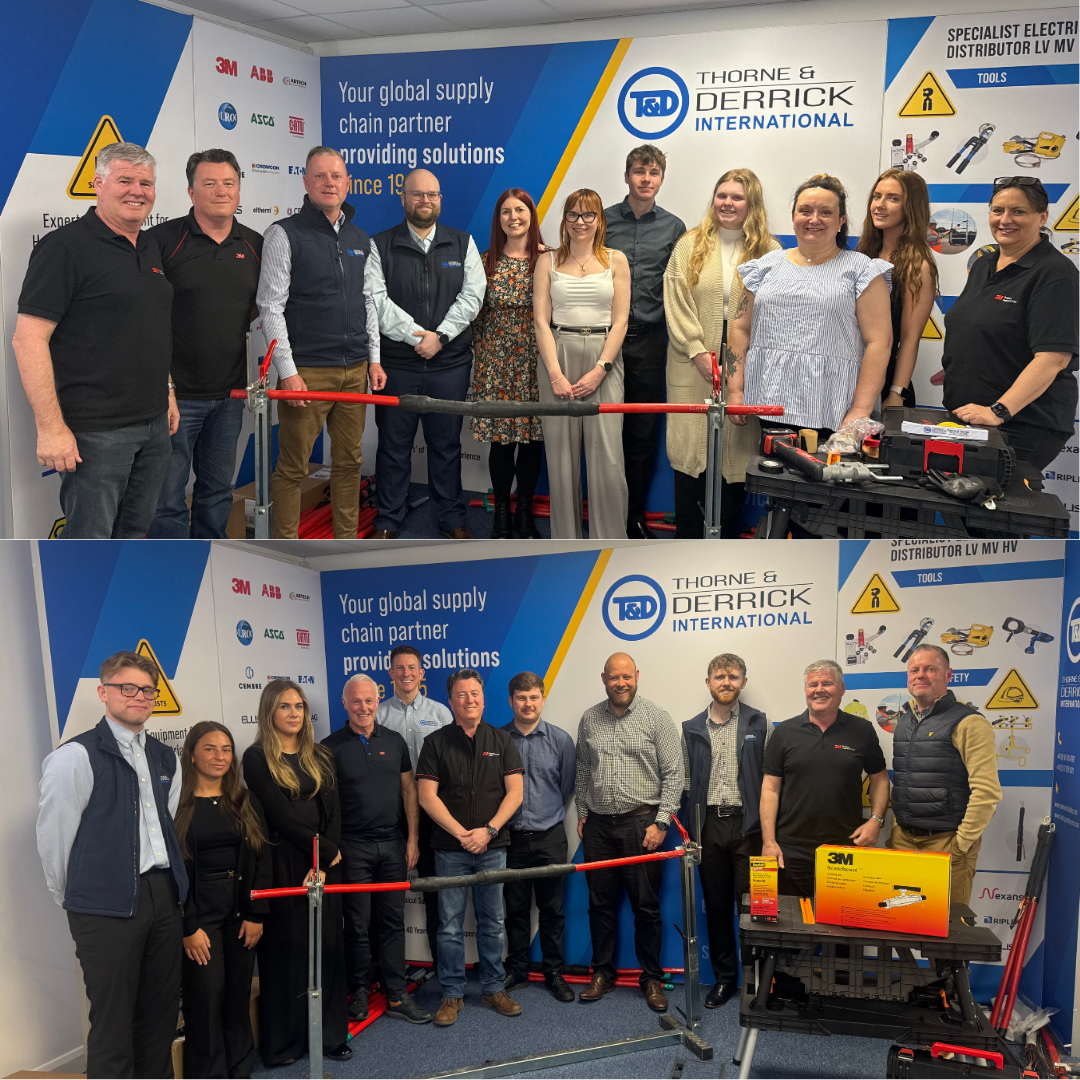
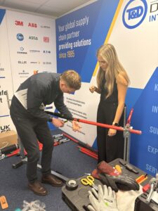
Thorne & Derrick Team Takes Part in 3M Cable Jointing Training
Continuous learning and hands-on experience are essential in the electrical industry especially when working with critical infrastructure across LV and MV systems.
Recently, the Thorne & Derrick team took part in an in-depth 3M cable jointing training session, focusing on improving technical knowledge, product understanding and real-world application.
The session brought together team members from across the business, combining theory with practical demonstrations to strengthen confidence in specifying and supporting cable jointing and termination solutions.
3M cable jointing training with the Thorne & Derrick Team
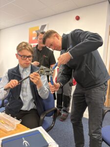
The training session provided an excellent opportunity for the team to step away from day-to-day roles and engage directly with the products and techniques used in the field.
From working with jointing materials to observing installation methods, the day focused on building a deeper understanding of how solutions perform in real-world environments.
Covering everything from tapes and Scotchcast resins to LV & MV Joints and Terminations, the session offered both technical insight and practical experience—bridging the gap between product knowledge and real-world application.
Understanding Cable Jointing in LV & MV Systems
Cable joints and terminations are critical points within any electrical network. Whether connecting sections of cable or safely terminating them at equipment, these components must maintain electrical integrity under demanding conditions.
During the training, key focus areas included:
- Preparation of cables prior to jointing and termination using correct cable jointing tools
- Selection of appropriate materials for insulation and sealing
- Installation techniques for both LV and MV systems
- Common installation errors by HV Jointers and how to avoid them
For those specifying or supplying equipment, understanding these processes is essential when recommending solutions such as LV cable joints and MV cable joints.
The Role of Tapes & Resins in Cable Jointing
A significant portion of the session explored the use of electrical tapes and resins, which play a vital role in insulation, protection and environmental sealing.
- Insulating tapes are used to rebuild insulation layers and provide dielectric strength
- Sealing tapes help prevent moisture ingress and contamination
- Resin systems provide robust encapsulation for joints, particularly in harsh environments
These materials are commonly used alongside cable jointing systems to enhance performance and durability. For example, Scotchcast resin-based solutions are widely applied in underground or submerged installations where environmental protection is critical.
Heat Shrink vs Cold Shrink: What’s the Difference?
One of the most valuable parts of the training was understanding the difference between heat shrink and cold shrink technologies—two of the most widely used methods for cable jointing and termination.
Heat Shrink Technology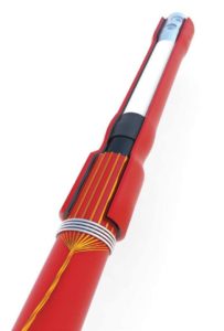
Heat shrink products are installed using controlled heat (typically via a gas torch), causing the material to shrink tightly around the cable.
- Provides a strong, durable seal
- Excellent mechanical protection
- Widely used across LV and MV applications
However, installation requires trained personnel and careful handling of heat sources, particularly in sensitive environments.
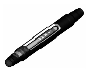 Cold Shrink Technology
Cold shrink products are pre-expanded and mounted onto a removable core. Once positioned, the core is removed and the material contracts automatically.
- No heat required – safer for hazardous or confined environments
- Faster installation time
- Consistent application with reduced risk of error
This makes cold shrink ideal for applications where speed, safety and repeatability are critical.
Terminations: Ensuring Safe Connections at End Points
While joints connect cables together, terminations are responsible for safely connecting cables to equipment such as switchgear, transformers and panels.
The training demonstrated how proper termination:
- Prevents electrical stress at the cable end
- Maintains insulation integrity
- Reduces the risk of partial discharge and failure
Both heat shrink and cold shrink technologies are widely used in cable termination systems, depending on the application and installation environment.
Why Product Training is Essential in the Electrical Industry
With increasing demand for reliable power across industries, the margin for error in cable installation continues to shrink. Training plays a key role in ensuring:
- Correct product selection for the Jointing, Termination & Abandonment
- Safe installation practices
- Compliance with industry standards
- Improved long-term performance of electrical systems
Key Takeaways from 3M Cable Jointing Training
- Understanding the difference between heat shrink and cold shrink is critical for correct product selection
- Tapes and resins play a vital supporting role in insulation and protection
- Proper jointing and termination directly impact system reliability and safety
- Hands-on experience significantly improves technical understanding
- Training ensures confidence when specifying and supplying electrical solutions

Cable Sealing with 3M Scotchcast Resin
February 14th, 2025
Cable Sealing with 3M Scotchcast Resin
3M Electrical Liquid Resin 2123
3M Scotchcast Resin 2123 is a two-part, unfilled polybutadiene resin designed for temperature curing – the resin from 3M Electrical offers the following features, consistent across the full range of 3M Scotchcast Electrical Liquid Resins: this re-enterable resin is ideal for low voltage cable sealing and insulation in electrical boxes. It comes with the Easy Dispenser 250, ensuring a cleaner application with reduced waste.
The 2123 Resin is formulated for virtually every electrical application requiring a soft, re-enterable resin with good handling and performance characteristics up to 1000 Volts.
Contact us for 3M Electrical technical support, specification guidance or assistance on the selection of electrical insulating resins for all LV MV HV applications.

3M 2123
Scotchcast Electrical Liquid Resins
Typical Property Data – Room Cures
- Polymer Cure/Cured Form/ Filler/Colour – Polybutadiene Room-Temperature Soft, re-enterable Unfilled Translucent Amber
- Temperature Class – 0
- 3M Electrical Liquid Resin Product Number – 2123
- Mixing Ratio – Wt 1:1 Vol (%) 48:52
- Viscosity at 23°C (73°F) (Centipoise) – A = 350-750* B = 700-1400*
- Cure Schedules (Temp/Time) – 21°C (70°F) 24 hrs.
- Gel Time – 62 min
3M Scotchcast Re-Enterable Electrical Insulating Resin 2123 is a soft, two-part polybutadiene resin designed for cable splice protection. It offers excellent handling and performance features and is formulated to be re-enterable for splice sealing. This versatile resin bonds effectively to most cable jackets while providing moisture sealing.
The resin is characterised by good wetting properties and low viscosity, ensuring ease of application. It cures at room temperature and functions as an insulating material for cable splices up to 1 kV. Its flexible, soft nature allows it to flow smoothly, even at low temperatures, filling enclosures and reducing voids. It is tested in accordance with CENELEC HD 623.S1 (EN50393) standards and complies with 2011/65/EU (RoHS) and 1907/2007/EC (REACH) regulations.
3M Scotchcast Resin Features
- Re-accessibility of the cable connection
- Homogeneous and reliable insulation
- Good adhesion of the resin on cables and on itself
- Excellent protection against water
- Low exothermic reaction temperature (0,6 K raise from 24° C)
- Continuous operating temperature of the resin at 90° C, emergencies up to 130° C
3M DISTRIBUTORS, STOCKISTS & SUPPLIERS

Thorne & Derrick provide competitive prices and fast delivery from stock for the complete range of 3M Scotchcast and Cold Shrink cable joints, terminations, resins and Scotch electrical tapes – we stock high voltage cable joints and terminations manufactured from 3M using Cold Shrink for 11kV and 33kV cables.
3M Terminations | Surface Tracking on Medium Voltage Cable Terminations
October 4th, 2024
Surface Tracking – 3M Medium Voltage Cable Terminations
Surface Tracking on Cable Terminations
Surface tracking is the irreversible damage and degradation on the surface of a medium or high voltage cable accessory or insulative material, such as a cable termination, due to the formation of conductive, carbonized paths.
Tracking results when discharges cause carbon to be left on an insulating surface as a result of the degradation caused by the heat of the discharge. This carbon deposit will grow to eventually create a continuous conducting path, which will lead to catastrophic failure.
Cold Shrink & Condensation In Medium Voltage Switchgear & Cable Terminations
Hydrophobic silicone Cold Shrink terminations provide excellent performance in Medium Voltage electrical equipment, such as switchgear, where cables endure temperature fluctuations caused by thermal cycling when under load – this “heating and cooling” effect condensates potentially causing premature partial discharge at the cable termination point. 3M Cold Shrink technology has a material tendency to reject and repel moisture accumulation and thereby reducing the probability for discharge-initiated erosion and tracking on medium/high voltage cable terminations.
N2XS(F)2Y Cable Terminations 12/20 22kV 24kV
Energising Data Centres | The QTIII range of MV Terminations are approved and in widespread service throughout the data centre sector for 12/20 (24)kV connection of N2XS(F)2Y Medium Voltage Cables with XLPE Insulation, Copper Wire Screen and Stranded Copper Conductor to BS EN 60228 into electrical switchgear equipment.

Surface Tracking Causes
Carbonized paths can occur from the dielectric breakdown of insulation, and/or by the introduction of contaminants on the surface that allow for electrical discharges across the surface.
The 3 factors that enable surface tracking to occur on cable terminations (MV HV):
Contamination |
Moisture |
Voltage |
| Dirt/Dust | Rain/Mist/Snow | Electrical Stress |
| Salt | Condensation | |
| Chemicals | Fog | |
| Pollutants | Humidity | |
| Other particulates |
Hydrophobicity
3M Terminations | Protecting Against Tracking
Tracking is defined as a process that produces localised irreversible deterioration on the surface of an insulator, resulting in the loss of the insulating function by the formation of a conductive path on the surface of the insulator.
Silicone is an excellent track resistant material and is hydrophobic, repelling water and making the insulator self-cleaning which results in a dryer surface and lower leakage currents. 3M outdoor cable terminations include 3M rain sheds which disrupt any wet leakage paths that occur in industrial environments and also allows the creepage distance of the termination to be much shorter.
 Insulator Skirts
Use of skirts on cable terminations increases the creepage distance (leakage distance) between the voltage source and ground plane. The undercut skirts disrupt wet leakage paths that occur in outdoor environments.

Advanced Materials
Insulators and skirted assemblies are made of formulated silicone rubber, which has excellent tracking resistance and hydrophobic properties. Special High K materials formulated to effectively control electrical stress.

Effective Stress Control
Electric field stresses are distributed in a controlled manner along the entire termination length. Voltage stress concentrations on the insulator surface are kept below 15 V/mil at rated voltage.
Further Reading
- 66kV Terminations | NEW Stock Introduction for 3M Cold Shrink Cable Terminations
- Stress Control | MV Cable Terminations by 3M Electrical
- Cable Jacket Repair | 3M Electrical Webinar
3M DISTRIBUTORS, STOCKISTS & SUPPLIERS
Thorne & Derrick provide competitive prices and fast delivery from stock for the complete range of 3M Scotchcast and Cold Shrink cable joints, terminations, resins and Scotch electrical tapes – we stock high voltage cable joints and terminations manufactured from 3M using Cold Shrink for 11kV and 33kV cables.
LV, MV & HV Jointing, Earthing, Substation & Electrical Eqpt
Thorne & Derrick International are specialist distributors of LV, MV & HV Cable Installation, Jointing, Duct Sealing, Substation & Electrical Equipment – servicing UK and global businesses involved in cable installations, cable jointing, substation, overhead line and electrical construction at LV, 11kV, 33kV and EHV.
THORNE & DERRICK Product Categories: Duct Seals | Cable Cleats | Cable Glands | Electrical Safety | Arc Flash Protection | Cable Jointing Tools | Cable Pulling | Earthing | Feeder Pillars | Cable Joints LV | Joints & Terminations MV HV
Thorne & Derrick Certificated by 3M for Medium Voltage Training & Product Familiarisation
August 20th, 2024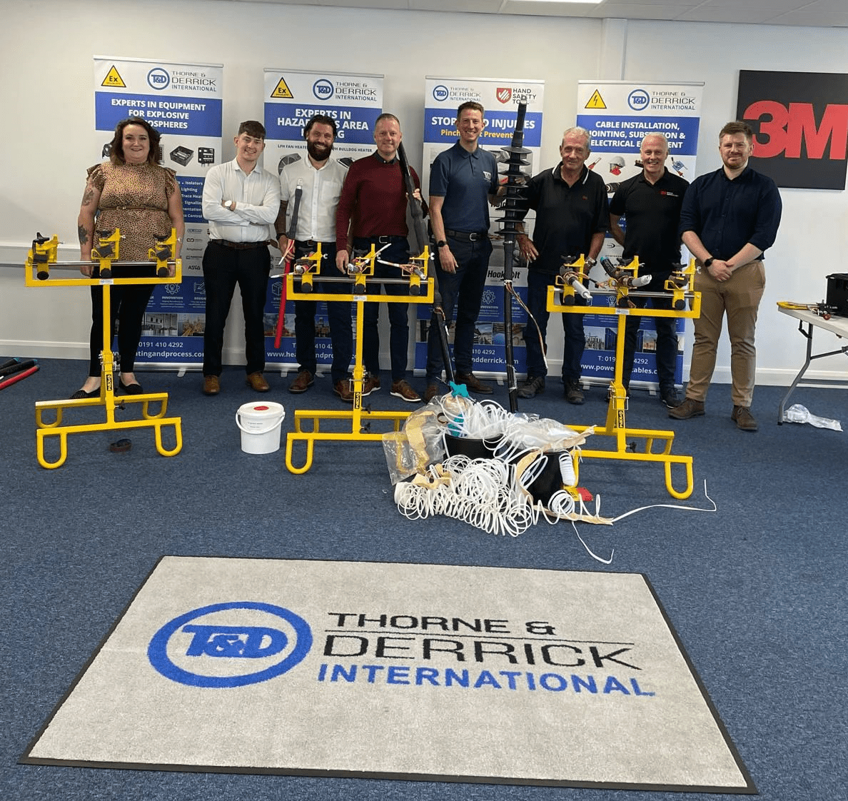
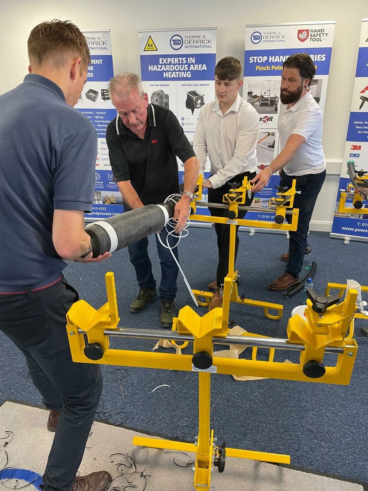
Thorne & Derrick have successfully hosted the 3M Electrical “Train the Trainer” Programme and are now the first Certificated UK Distributor for this innovative scheme introduced to support MV Cold Shrink Cable Accessory installation competency.
T-t-T has been conceived by 3M to empower their Approved UK Distributors to deliver Product Training and Demonstrations to customers and ensure the highest levels of installation quality and safety are achieved – reducing cable failures, increasing reliability and securing both the revenue and reputation of asset managers and owners.
We had the privilege of welcoming industry expert Allan Russell (Application Engineering Specialist at 3M United Kingdom) who provided excellent tuition and guidance to our team of Technical Sales Engineers on the installation process of 11/33/66kV Cold Shrink Joints and Terminations.
The focus for the 2 days intensive session was the advancement of education, skills and technical knowledge for our Sales Team to best support the Medium Voltage Cable Accessory requirements of all industries – we covered all practical aspects of Cable Preparation & Accessory Installation for the 3M Cold Shrink ranges of Joints & Terminations covering voltage classes 11kV, 33kV and 66kV.
“The Train-the-Trainer concept enables Thorne & Derrick, as a Specialist Distributor for 3M Electrical since 1985, to bolster our customer service and field support to clients and is the perfect complement to our recent appointment as Approved 3M Electrical Kitting Partners – this is a further formidable personal achievement for Jonny Hewitt and another business accolade for Thorne & Derrick,” comments Chris Dodds (Sales & Marketing Manager – Thorne & Derrick).


Rail Electrification Innovation | The next-generation of 25/45/52kV Network Rail PADS ColdShrink Joints with Concentric Neutral, stocking at Thorne & Derrick.


Further Reading
- Thorne & Derrick Electrifying Industry With 3M
- Thorne & Derrick Appointed 3M Electrical Kitting Partners

Thorne & Derrick are Specialist Distributors to EPC’s & Contractors working on the design, construction and maintenance of UK, European and international projects supplying an extensive range of LV HV Cables, Accessories Jointing, Substation & Electrical Eqpt – this includes Hazardous Area (ATEX & IECEx Certified) Equipment to provide Power, Heating & Lighting to the Potentially Explosive Atmospheres industries.
Based in the UK, we are highly customer responsive and absolutely committed to providing a world-class service.
Since 1985, we have provided expert technical support and express delivery from extensive UK stocks to world-wide destinations.