

Blog
Cable Strikes | How To Support LV to 33kV Electricity Cables
May 11th, 2021
Cable Strikes
Utility Strike Avoidance Group
USAG have published a range of documents to assist industry understanding of the root cause and contributory factors behind specific incidents. The aim is to improve industry standards and reduce the number of cable strikes.
Cable damage is often caused by excavating machines – hand held tools such as pneumatic drills, crowbars, pins, picks and forks also expose workers to potential sources of danger when digging around underground cables.
The next in the series is a safety alert thanks to Highway England regarding incidents caused by contractors incorrectly supporting power cables.
Incident Overviews
Below are some case studies and a useful guide on how to support exposed LV to 33kV cables spanning your excavation, supplied by SP Energy Networks.

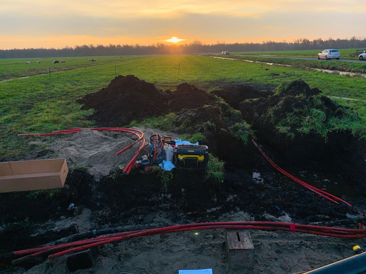
The above image highlights a situation which could easily be avoided if the correct planning processes had been implemented at the pre-construction phase of the project.
The task for the contractor was to expose the utilities and excavate a further 3 metres past the electrical network, leaving the low voltage (PILC) cable supported with rope at two locations.
The inadequate level of support of the electrical network at this location is not acceptable to ScottishPower; the contractor was advised to backfill the exposed cable with caution.
Given the ongoing mechanical excavations, lack of cable support and that contact with the electricity network was a possibility the contractor was advised to contact SP Energy Networks Customer Connections department to progress a cable deviation to remove the hazard.

The above image demonstrates how NOT to support an electricity cable.
The contractor has gone some way to supporting the Low Voltage cable in the correct way by using sturdy batons and ratchet straps, however the weakest part of the electrical network are the LV cable joints.
ScottishPower would recommend that exposed cables with joints should not be supported in this situation at any time due to the probability of the weight of the joints pulling the cables out of the joint connections. To carry out support of electrical cables a method statement and a safe system of work will be required by ScottishPower prior to works being undertaken.
The contractor has gone some way to supporting the underground network cables by using ratchet straps, however in this situation the cables are all bunched together and have sagged. The weakest part of the electrical network in this situation are the cable joints with the added weight of the exposed cables.
ScottishPower would recommend that exposed cables with joints should not be supported in this manor due to the probability of the weight of the joints/sag on the cables pulling the cables out of the joint connections. Every excavation has different dimensions to consider prior to carrying out work to support the electrical cables.
A method statement and a safe system of work will be required by ScottishPower prior to support works being required on the electrical network.
 The above image highlights a situation which clearly highlights the incorrect method of supporting a live underground electrical cable.
The inadequate level of support of the electrical network at this location was not acceptable to ScottishPower; the contractor was advised to support the exposed cable with caution to the correct ScottishPower requirements.
Given the ongoing mechanical excavations and the lack of adequate support, contact with the electricity network was a possibility the contractor was advised to contact ScottishPower EnergyNetworks Customer Connections department to progress a cable deviation to resolve the situation.
➡ Thorne & Derrick distributes Insulated Tools for the Rail & Utilities industries manufactured to British Standard BS 8020-2011.

The above image highlights a near miss situation which could have been easily avoided if the correct processes were implemented at the planning stage of the project, as opposed to attempting to rectify the avoidable situation at the construction phase.
On this occasion the project to construct an extension to an existing building had started, SP EnergyNetworks were contacted and advised the main contractor that the existing low voltage underground cable traversing through the foot print of the proposed extension would require to be deviated.
Further advice was delivered, highlighting that the existing cable should not be constructed over. The advice given was not adhered to and the contractors proceeded to excavate and install concrete foundations around the existing underground electrical network.
This course of action left the cable unprotected and open to the elements, the cable being concreted over at various locations and being supported in an unprofessional manor. During operations to excavate the foundations of the extension the electrical cable was damaged, fortunately on this occasion no injuries occurred to the operatives.

The above image demonstrates how not to support electricity cables.
The above image highlights a near miss situation which could easily have be avoided if the correct processes had been implemented at the planning stage of the project, as opposed to attempting to rectify the avoidable situation at the construction phase.
On this occasion the contractor progressed with the project despite being advised that a cable deviation would be required, and that the underground electrical network was not to be constructed over.
The contractor’s decision to progress construction placed operatives in danger which resulted in the low voltage cable being damaged. Despite the cable being damaged, excavations continued with the cable being exposed, covered in concrete and supported at various locations.

LV MV HV Voltage Detectors | Portable Earthing | Insulating Sticks | Insulating Gloves | CATU Electrical Safety Equipment
RAMS Generic Guidance For Supporting/Exposing/Operating Around SP EnergyNetworks Underground Distribution Electrical Cables:
33KV – High Voltage – Low Voltage Cables:
- Ensure all machine operators/site traffic drivers/operatives/visitors are made aware of all cable routes on construction site at initial site induction.
- Prior to works commencing, works area should be marked/highlighted (install signage at excavation location) to ensure all operatives are aware of the presence of the underground electrical network in the works area, this information also to be promoted continually throughout the remainder of the onsite works. (Task specific tool box talk also required prior to works commencing to ensure everybody understands the scope of works to be undertaken around the underground electrical network, their collective/individual roles to be clearly defined ensuring the required task is completed in a safe environment)
- Procure SP EnergyNetworks cable records (UMV System: Utility Map Viewer)
- Excavations as per HSG47 hand excavate to uncover all electrical cables/utilities in vicinity of proposed works.
- Supporting cables: If excavation length on electrical cables exceeds 1.2m cables will require to be supported.
- Install split cable ducting (150mm) around all exposed cables (for protection purposes only)
- No sudden movement of cables to take place. (minimum movement when placing split ducting around all cables)
- Provide substantial support beam above the cables, spanning across the exposed cable excavation, caution when placing/removing support beam. Ratchet straps are to be utilised to support the split ducted cables from the beam above.
- Ratchet straps to be of sufficient size/quality to support the weight of the split ducted cable, and are to be tensioned until they hold the ducted cables weight only, prevent any over strain on the ducted cables. Ratchet straps to be placed at 1m intervals.(Please note: no rope/string to be used to support underground cables)
- Once the ducted cables are sufficiently supported with the ratchet straps/supporting beam the hand excavation shall continue to clear 500mm beneath the existing cables. (Ensure the ducted cables will not sag at any exposed length of the cable)
- Cable records indicate no joints on cables at locus of proposed excavations, however if cable joints are located, excavation works to cease immediately and SP EnergyNetworks to be contacted for further guidance.
- Great care to be taken when installing the drainage pipe/other, that contact with the electrical network is avoided.
- Great care to be taken when installing/removing shoring/drag boxes etc that contact with the electrical network is avoided
- Caution to be taken when backfilling excavation around the existing cables, backfill to underside of cable, remove split ducting, sand cables with 150mm of sand, install marker tape.
- Continue to backfill with caution.
No SP EnergyNetworks cables to be supported at any time without SP EnergyNetworks authorisation. Contractors proposing to support the underground electrical network are to produce a risk assessment – method statement to formalise the advice described above to demonstrate to SP EnergyNetworks that risk assessments/method statements/safe systems of work will be implemented to ensure a successful conclusion to this stage of the project. The risk assessment/method statement shall be passed to SP EnergyNetworks for review/approval prior to excavation/supporting cable works commencing on site.

Cable Hangers | Cable Ducting | Cable Protection | Electrical Safety Equipment
Protecting Cables Against Strikes & Restoring Power Post-Strike
Thorne & Derrick have been distributors for 3M Electrical since 1985 and can provide a range of reliable and easy to install Cable Repair Products – this includes Scotch Tapes, Scotchcast Joints and Cold Shrink Tubes to provide effective re-instatement of cable sheath jackets on all types of LV MV HV cables in onshore and offshore locations with safe or hazardous area workplace classifications.

Cable Repair Products
Our range of cable protection covers manufactured by Centriforce provide underground utility protection of LV MV HV cables including Tapetile (11kV) and Stokbord (33kV 66kV 132kV) – contact us to discuss Cable Damage Prevention Products including Dectamesh, the underground detectable warning tape for alerting excavators of the presence of buried cables and to prevent potentially lethal accidents during excavation.
 and extra high voltage (132kV-400kV) power cable networks.")
Stokbord

Tapetile

Cable Strikes | Excavator Struck 11kV Overhead Power Lines
May 11th, 2021
Cable Strikes
Utility Strike Avoidance Group
USAG have published a range of documents to assist industry understanding of the root cause and contributory factors behind specific incidents. The aim is to improve industry standards and reduce the number of cable strikes.
Cable damage is often caused by excavating machines – hand held tools such as pneumatic drills, crowbars, pins, picks and forks also expose workers to potential sources of danger when digging around underground cables.
The next in the series is a safety alert thanks to Highway England regarding incidents caused by contractors incorrectly supporting power cables.
A Striking Reminder
Incident Overview

Critical and immediate safety action from the Deputy Director Health, Safety & Wellbeing
During river maintenance work a 21 tonne long reach excavator fitted with a weed cutting attachment, came into contact with an uninsulated overhead electricity cable rated at 11,000 Volts / 11kV. Fortunately no one was injured and the utility company repaired the damaged cable that day. Due to the potential consequences this has been classified a Safety Critical Incident. We have reported this dangerous occurrence to the Health and Safety Executive, who have been in contact with us about the matter.
The initial facts point towards the importance of implementing our established control measures.
The full facts and lessons learned will emerge in the review that has begun. However, the incident is an important reminder of the significant hazard presented by overhead powerlines. I am therefore reminding colleagues who undertake, supervise or manage work involving mobile plant and equipment of the key precautions that must be taken when travelling under or working near overhead powerlines.
Operations Managers must:
Brief those members of their teams who plan, supervise and undertake tasks involving mobile plant and equipment, and remind them to:
- Obtain up to date services information from statutory utility providers before the work commences
- Include the information on services in the Pre-Construction Information and/ or site pack for the activity
- Provide information on services and other hazards on a single map or plan of the site
- Implement all of the control measures specified in the risk assessment before the works proceed
- Carry out a pre-start briefing so that risks, controls and method of work are communicated to colleagues undertaking the task
- When plant is operating within 15 metres of overhead power lines, ascertain the voltage and height of the cables. This information is essential in determining exclusion zones, stand-off distances and for setting of height limiter devices
By close of business on 15 September 2020 all Operations Managers must:
Please note Safeguard is not being used to issue actions due to reliability problems (we shall shortly be moving Group Actions to Airsweb).
As an interim measure;
Confirm that the action is completed and that the appropriate personnel have been briefed as requested by using the voting buttons on the notification email.
Remember; taking these actions could prevent a colleague being hurt or seriously injured – This action was approved by the review team on 8 September 2020
To support this action, active monitoring suggestions include:
- Check if services information is included in site packs
- Ask site teams if they know the voltage and height of the overhead power lines they are working near or travelling under
- Check quality of site maps and plans to see if hazard information is included
Cable Strikes | Cable Hangers | Cable Ducting | Cable Protection | Electrical Safety Equipment
Protecting Cables Against Strikes & Restoring Power Post-Strike
Thorne & Derrick have been distributors for 3M Electrical since 1985 and can provide a range of reliable and easy to install Cable Repair Products – this includes Scotch Tapes, Scotchcast Joints and Cold Shrink Tubes to provide effective re-instatement of cable sheath jackets on all types of LV MV HV cables in onshore and offshore locations with safe or hazardous area workplace classifications.
Cable Repair Products
Our range of cable protection covers manufactured by Centriforce provide underground utility protection of LV MV HV cables including Tapetile (11kV) and Stokbord (33kV 66kV 132kV) – contact us to discuss Cable Damage Prevention Products including Dectamesh, the underground detectable warning tape for alerting excavators of the presence of buried cables and to prevent potentially lethal accidents during excavation.
Stokbord
Tapetile
Why Large Offshore Wind Farms Should Double Their Intra-Array Voltage
May 11th, 2021
-
Reproduced with kind permission of Mane - Worldwide Recruitment Specialists.
Offshore Wind Farms
Offshore wind farms are now the biggest contributor of green energy to the National Grid. But the cost of installing and running them is problematically high – and the race is on to solve that problem as the 2050 net-zero deadline looms closer.
Could pumping up the intra-array voltage from 33kV to 66kV be the answer?
A Carbon Trust study found that increasing to either 48kV or 66kV would cut costs and increase yields over the life cycle of a wind farm. Of the two, 66kV brought the bigger benefits.
While 33kV is the most practical choice for wind farms at present, it means the power has to be stepped up to a much higher voltage like 110kV at an offshore substation for transmission in the UK. This generates massive costs in cabling and substations, which are often remote and difficult to access.
Higher voltage array technology should not only cut these costs but also boost efficiency by preserving more of the energy the wind farms generate.
The Carbon Trust predicts that switching to 66kV could reduce the cost of offshore wind power by 1.5%. To encourage this, it launched a competition to fast-track the development of 66kV cables, “The Race for 66kV”, awarding funding to three winning companies, Prysmian, Nexans and JDR.
Phil de Villiers, the Carbon Trust’s Head of Offshore Wind, said higher voltages could increase transmittable power by over 100%, and also make it possible to develop much larger arrays with more turbines per array.
Developers are already showing interest, including major players like Eon, RWE Innogy, ScottishPower Renewables, Dong, Statkraft, Vattenfall, SSE, and Statoil.


See how T&D support, supply and service the Renewable Energy industry.

Thorne & Derrick are Specialist Distributors to the UK and international Offshore Wind & Renewable industry to provide safe and reliable LV HV Electrical Cable & Power Distribution Systems up to 66kV – we are highly customer responsive and absolutely committed to providing a world-class service.
Contact our UK Power Team for competitive quotations, fast delivery from stock and technical support or training on all LV-HV products.
Key Product Categories: Duct Seals | Cable Cleats | Cable Glands | Electrical Safety | Arc Flash Protection | Cable Jointing Tools | Cable Pulling | Earthing | Feeder Pillars | Cable Joints LV | Joints & Terminations MV HV
Modular Substation Cable Termination Design | Roxtec Whitepaper
May 11th, 2021
Abstract
The methods for cable penetrations into modular industrial substations are summarised using cable transits manufactured by Roxtec.
The requirements for structural and environmental integrity, grounding, sealing, fire protection and ease of expansion for a cable termination system are discussed. Current methods of installation are compared to using a cable transit design for installing and terminating cables in electrical substations.
Index Terms – cable termination, modular substation, cable transit.
Introduction
Modular substations are becoming the preferred approach for installing electrical and control equipment in industrial facilities.
The ability to prefabricate a building, pre-install both electrical and control equipment and the ability to pre-commission equipment prior to the installation helps to reduce on-site construction installation costs. This is particularly advantageous in remote project locations where the cost of labour can be very high.
The on-site termination of conductors and cables into equipment can often be an issue.
The equipment layout, the design of the modular building skid base frame, the number of terminations and the termination method can all influence the speed and ease of installation. Choosing the wrong penetration approach can compromise the environmental integrity of the building and equipment, significantly increase installation cost and complicate the ability to install cables and conductors in the future.
This has a direct impact on the cost of ownership over the life of the asset.
Modular Substation Fundamentals
A typical modular substation consists of a steel frame skid base supporting a prefabricated insulated panel constructed building.
The dimensions of the building can vary and is usually determined by the amount of equipment installed and the transportation logistics for a project.
It is common to see substation buildings with dimensions in excess of 30 meters in length, 7 meters wide and 6 meters high for domestic onshore projects. If the equipment layout dictates a larger building footprint, often the building will be split in two for transport to site.
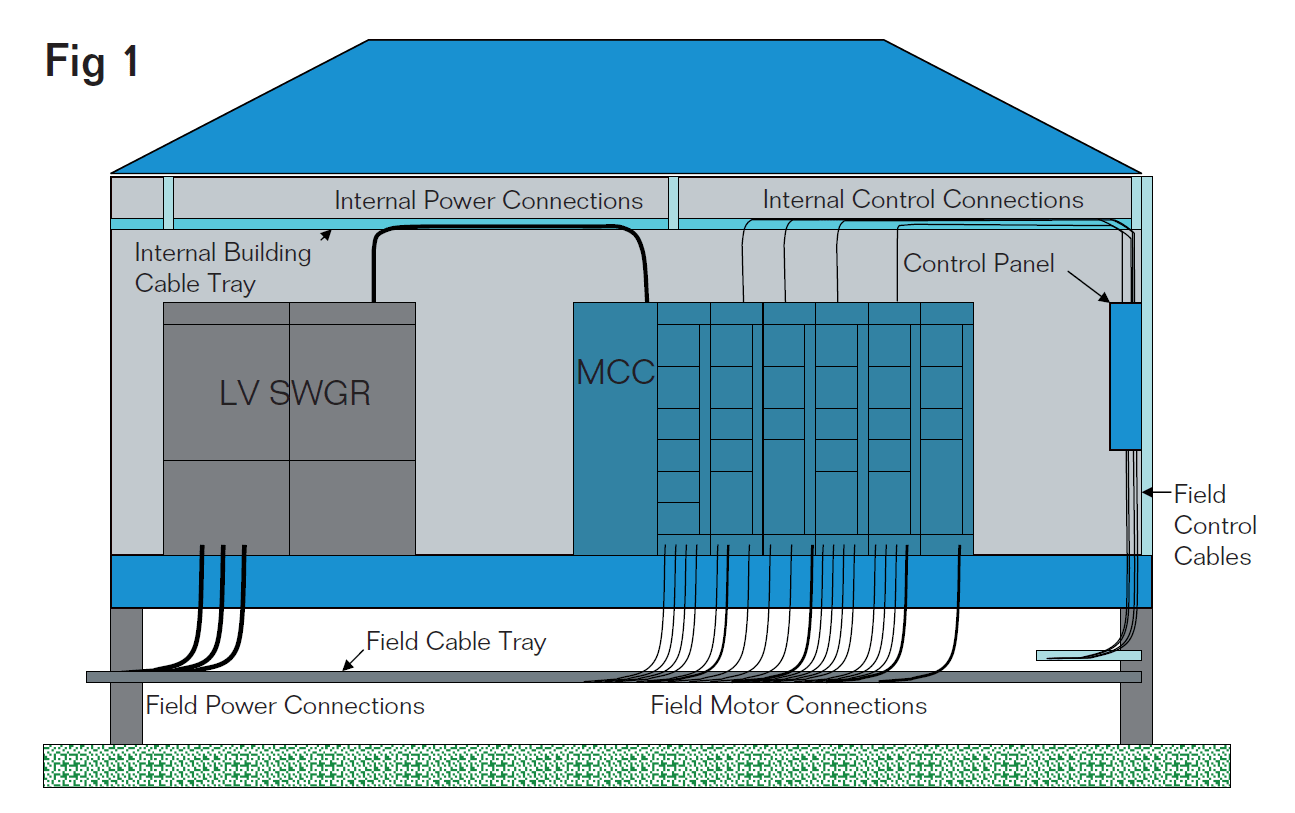
Interconnecting wiring between equipment is usually done in one of two ways. If the substation is constructed on raised piles, and the wiring connections are internal to the substation, the conduits or cables are run overhead within the substation.
External field cable connections are then terminated into the floor of the substation directly into the equipment item. This approach has the advantage of minimising the height of the building and allowing for convenient access for workers to terminate field cables.
Fig. 1 illustrates this concept.
Modular Substation Cable Termination Design | Figure 1
Terminating Cables in substations
There are a number of challenges associated with terminating cables in a modular substation.
The first being the number of field terminations. In a medium sized industrial substation servicing a large number of motor interconnections, there may be up to 300 or more power and control cable terminations. The terminations must be coordinated with the location of the electrical and control equipment and the skid frame steel members supporting the building.
Often, a large number of cables must be terminated in a very limited area leading to cable and connector congestion which can impact worker productivity. Another challenge associated with terminating field cables is maintaining the environmental integrity of the equipment and the substation building envelope. This requires that the termination method maintain a vapour-tight weather barrier with a suitable insulation ‘R’ factor value to avoid condensation within the equipment and the building envelope.
The cable termination method should also provide a fire resistant barrier in the unlikely event of a fire. The cable termination method must accommodate a variety of cable construction configurations and wiring methods.
Cable diameters can vary with some control conductors with diameters of 5 mm or less to 3/C 500MCM armoured power cables which may have diameters of 100 mm or more. In each case, the cable must be properly secured and grounded in accordance with the local electrical installation codes and requirements. One often overlooked aspect of the cable termination method is the ability to add cables in the future.
The flexibility to easily add additional cable can pay dividends even during the initial installation when design modifications are made late in the installation phase of a project.
Traditional cable termination options
There are several cable termination methods currently used to terminate conductors into industrial substations. Some projects prefer that all cables are terminated into the top of electrical and control equipment mounted inside the building. A cable transit barrier is often used to allow cables to pass through an exterior wall.
Fig. 2 illustrates a method where cables are terminated into the floor of a substation. A ¼” steel removable panel is used to facilitate the pre-drilling of holes for the cable connectors prior to the field installation. This helps to improve construction productivity by allowing the majority of the cable connector entry holes to be drilled in a shop environment. Once the connector plate is fastened in place, drilling becomes more difficult and time consuming.
There is also the potential for metal filings to contaminate the switchgear cable termination compartment. Each connector hole must also be de-burred to prevent the conductor insulation from being damaged when the cable conductors are pulled into place. A second option for terminating cables is illustrated in Fig. 3.
A section of the floor is removed and the cable is terminated directly into the floor mounted equipment. Some equipment, such as low voltage motor control centres (MCCs) incorporate a removable plate to facilitate the punching of holes for cable connectors. The removable plate is usually constructed of sheet metal steel and is easily punched using a hydraulic punch.
The primary disadvantage to this termination method is that large sections of the floor must often be removed to gain access to the underside of the equipment. This may compromise the structural integrity of the floor and building envelope.
Future cable entry is also difficult as access to the plate must be provided both above and below the cable connector location. In certain cases, if the plate is not of sufficient thickness, large cables can deform the plate, further compromising the integrity of the installation.
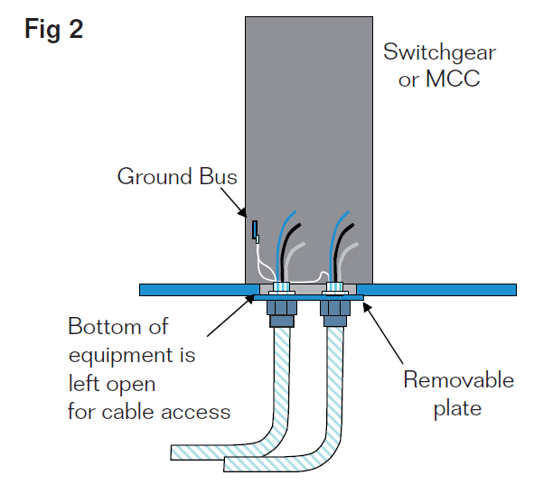
Cable Termination into Floor of Substation | Figure 2
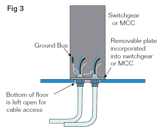
Cable Termination directly into Switchgear/MCC | Figure 3
Improved cable termination option
using a cable transit system
A third option for terminating cables into a substation is to use a transit entry frame. Fig. 4 illustrates a transit entry installation.
The transit frame is welded or bolted to the substation floor at strategic locations where cables will be terminated. The cables are then pulled into place through the transit frames and then sealed using Multidiameter™ cable transit blocks and a mechanical compression wedge.
The cable transit system provides cable retention and provides an environmental, fire resistant and gas tight seal to the equipment and building enclosure. There are several advantages to using a cable transit for cable entry in to a substation. The first being efficiency.
A cable transit allows multiple cables to be pulled at the same time though the transit opening. The large opening eliminates the potential damage to the conductor insulation during installation. Secondly, the transit frame maintains the structural and environmental seal integrity of the floor and allows for a high density and capital efficient installation of cables within a very small footprint. Also, future expansion capacity is provided for each transit via unused cable blocks which can be easily removed and reinstalled for future cable installation.
Another significant advantage of sealing cables with a cable transit system is the additional room below the building floor and equipment that is provided by the extension of the transit frame. This depth may be customised to a depth equal to the height of the structural steel, and has a standard depth of 60 mm.
This additional working space assists with the restrictive bend radius of larger armoured cables and allows for proper cable alignment with equipment configuration.
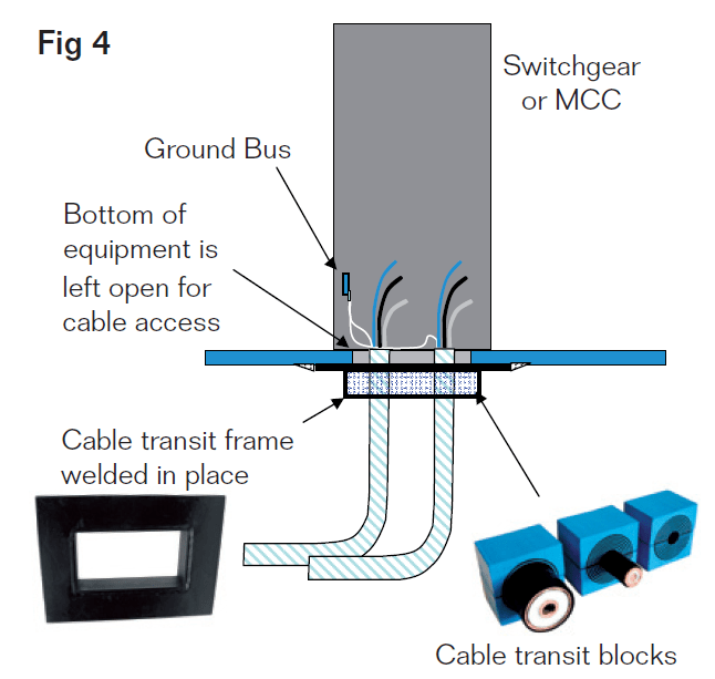
Cable Transit Installation for Switchgear/MCC Entry | Figure 4
Equipment Grounding for Tray Cables
There are two methods for terminating the bonding conductor of a tray cable using a cable transit system. The first involves connecting the bonding conductor directly to the ground bus of a switchgear or MCC. The PVC sheath is stripped back to the transit entry location and the bonding conductor is removed and connected to the equipment ground bus. The phase conductors then continue to the termination point in the switchgear or MCC. This is very similar to what occurs when a standard cable connector is used to terminate a conductor. Fig. 5 illustrates this method of bonding.
A second and less labor intensive option exists for grounding tray cables in MCCs. Some MCC manufacturers provide the option of a “unit” ground connection at the MCC bucket rather than on the equipment ground bus. This reduces the amount of cable sheath that must be stripped back in order to connect the bonding conductor to the equipment ground bus. This has the advantage of keeping the phase and bonding conductors together as an assembly within the equipment and breaking out the bonding conductor closer to where the phase conductor terminations actually occur. Fig. 6 illustrates this method of bonding.
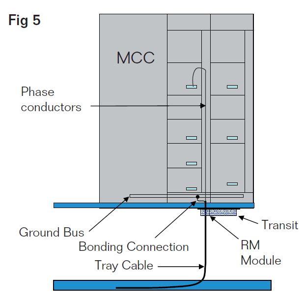
Option 1 for Grounding Tray Cable | Figure 5
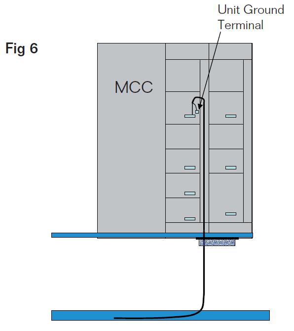
Option 2 for Grounding Tray Cable | Figure 6
Work process
To use a cable transit system to its fullest advantage, an understanding of the work process from design through final installation is required.
A. Engineering
The use of a cable transit for terminating cables into a substation requires pre-planning. The location of electrical and control equipment must be coordinated with the structural steel base to insure that transit frames of an adequate size and dimension can be installed without interference from support steel in the steel base. If possible, a standardised frame size helps to simplify the
design and installation process.
During the design phase, as cables are identified, they are assigned to a transit frame. This information can be integrated into the cable schedule or often dedicated software is used to create detailed transit schedules. Once the transit schedules are complete, the bill of material can be generated for both the substation fabricator and field installation contractor.
Fig. 7 illustrates a typical engineering drawing produced by Roxtec RTM Software for an MCC transit with capacity for 43 cables of various diameters installed within a 23 cm x 26 cm window. The flexibility of this system allows cable and pipe sizes ranging from 3 mm (.118 in) to 99 mm (3.898 in) to be sealed within the transit frames.
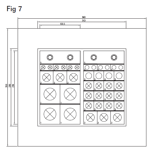
Engineering Drawing of Cable Transit System | Figure 7
B. Fabrication
Once the size of the cable transit and the locations are identified, the transit frames can be purchased and shipped to the fabricator for installation. The transit frames are mounted into the wall or floor by bolting or welding and then temporarily sealed for transportation to site.
C. Site Installation
After the modular substation is shipped to site and set in place, installation of the field conductors can begin. The site installation contractor will install interconnecting cables from source to destination via the cable transit openings identified on the cable schedule. The large opening provided by the cable transit helps the installer pull the cable into place and minimises any damage to the conductor insulation. When all cables for a cable transit are installed, the cables are secured and sealed using the cable transit blocks with stay plates and a mechanical compression wedge. The cable transit drawings help to identify what cables should be placed where and what size cable block should be used. The transit schedules also record how much spare capacity is available in each cable transit for future growth. Cables can be easily added without cutting or drilling additional holes, simply by loosening the compression wedge. Training is essential to help field installers understand the transit termination concept.
Training can be provided using on-site training services or by installation videos that provide step-by-step instructions. Once the installer has observed and installed the transit blocks for one transit installation, subsequent transit installations are easily completed. Figure 8 illustrates the installation of a transit barrier in a modular substation application.
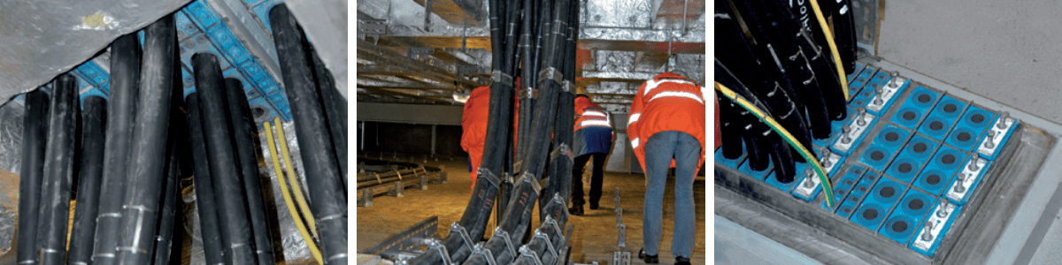
Figure 8
Conclusion
There are several advantages to using a cable transit for installing and terminating cables in industrial substations. It provides a standardized design with the flexibility to terminate a variety of different sizes and cable constructions. The ease of installation helps to reduce labor costs and minimize the potential for insulation damage. The structural and environmental integrity of the wall or floor penetration is maintained providing an insulated, vaportight and fire-stop barrier and cables can be easily added in the future. Cable transits are a viable alternative for terminating cables into industrial substations.
H. Vita
Allan Bozek, P.Eng., MBA graduated from the University of Waterloo in 1986 with BASc in Systems Design Engineering and a MBA from the University of Calgary in 1999. He is a Principal with EngWorks Inc., providing consulting engineering services to the oil and gas sectors.
Roxtec International AB, the parent of Roxtec, Inc. was established in 1990 and is the global leader in modular cable and pipe sealing systems. Roxtec maintains more than 250 registered tests and approvals and serves the oil & gas, telecom, marine, industrial and OEM industries in more than 70 markets around the globe.

LV MV HV Jointing, Earthing, Substation & Electrical Eqpt | Distributors for Roxtec Cable & Pipe Sealing Transit Systems
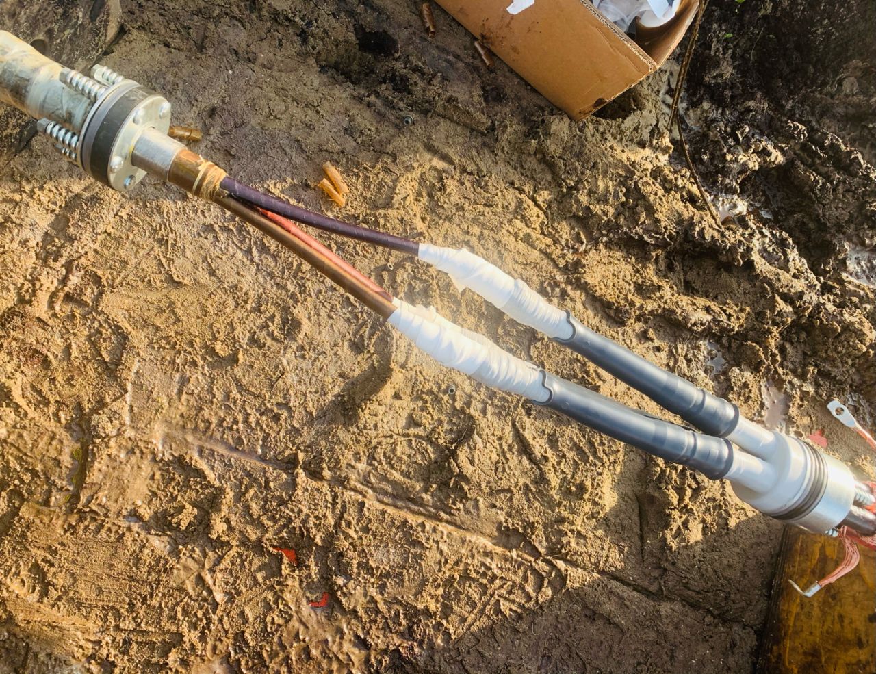
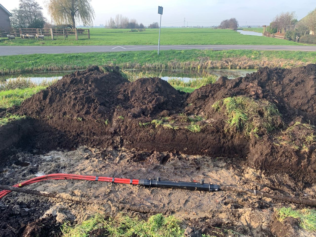
Kabeldon SMTXB Cable Joint
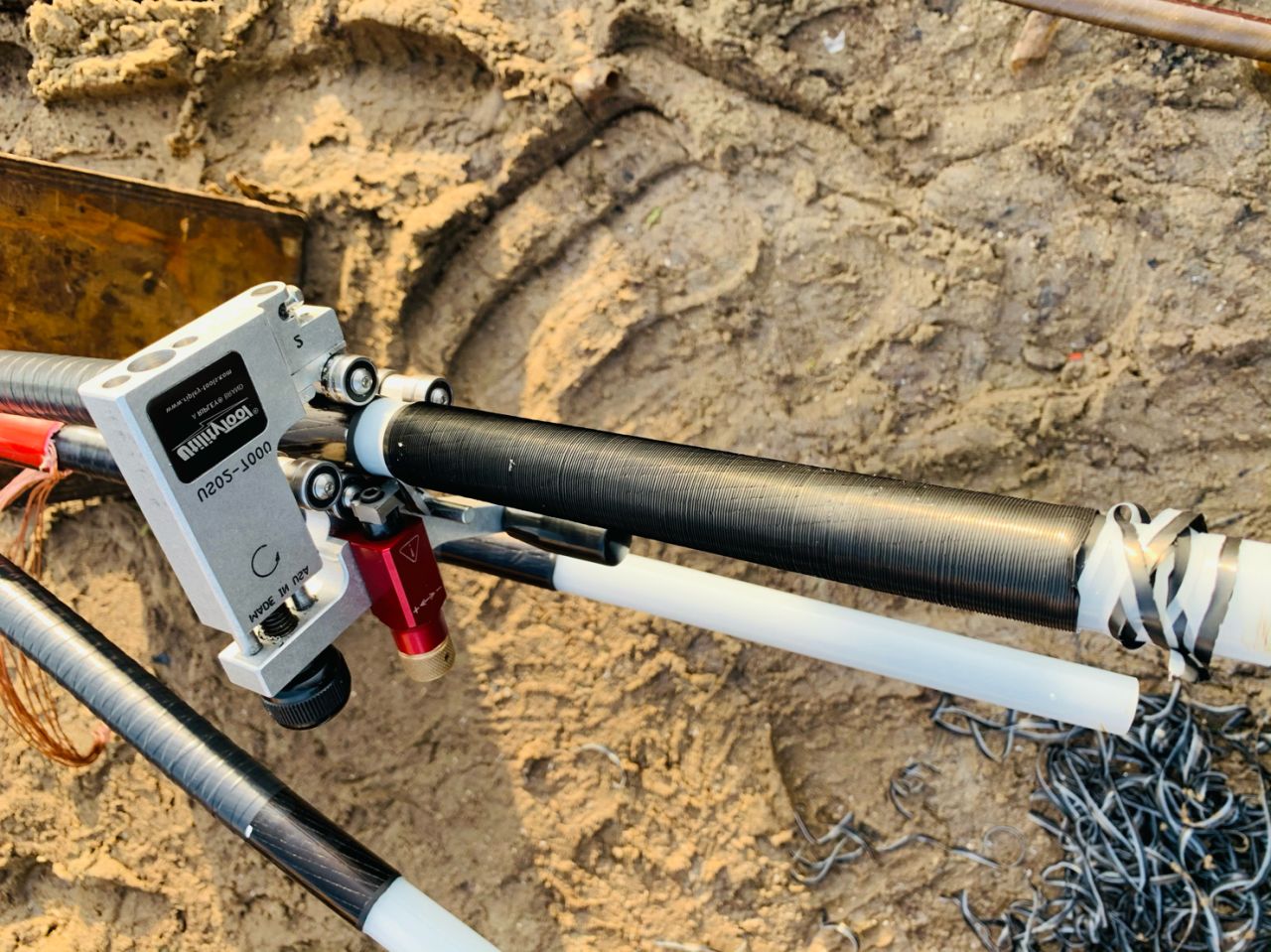
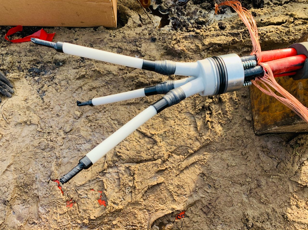
May 11th, 2021Images Coutesy of: Timo van der Harst – Eigenaar VDH Kabelmontage Laag- en Middenspanning, Vlaardingen, South Holland, Netherlands
Pictured: Kabeldon SMTXB Cable Joint

![]()
Jointers blog
Subscribe now to our POWER NEWSLETTER– a monthly email circulation packed with news, projects, videos, technical tips, training information, promotions, webinars, career opportunities and white papers.
Includes access to our popular JOINTERS BLOG with contributions from utility professionals, linesmen and cable jointers working on MV HV EHV cables and overhead lines typically at 11kV, 33kV, 66kV and up to 132kV.
15,000+ Subscribers. ➡ 
