

Blog
How To Resolve Rising Fault Current Levels On Your Overhead Network
May 4th, 2021- Special thanks to Jonathan Hopkins (Sales Director) at S&C Electric Company for the kind permission to republish the following article.
S&C Electric Company
S&C Electric Company is a leading provider of switching, protection and control solutions for medium voltage electric power systems. Headquartered in Chicago, S&C is applying its heritage of innovation to address challenges facing the world’s power grids and thus shaping the future of reliable electricity delivery. The mission of S&C is to continually develop new solutions for electricity delivery, fostering the improved efficiency and reliability required for the intelligent grid.
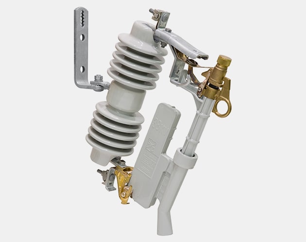
Resolving Fault Current Levels
Are You Experiencing Rising Fault Current Levels On Your Overhead Network?
This could cause miscoordination and existing assets to exceed recommended symmetrical fault ratings. The Fault Tamer, Fuse Limiter from S&C Electric safely addresses this issue by combining the function of a conventional fuse with the benefits of a current limiting fuse.
The S&C Fault Tamer combines the functionality of a conventional fuse cutout and a backup current-limiting fuse in one powerful, easy-to-install package for the protection of new or existing overhead pole-top transformers up to 25kV.
S&C Electric Company’s Fault Tamer is manufactured in accordance with a quality system certified to ISO9001:2000.
S&C Electric Fault Tamer, Fuse Limiter Variations
- 98021-D, 15 kV, 110 kV BIL
- 98072-D, 15 kV, 125 kV BIL
- 98022-D, 25 kV, 125 kV BIL
- 98052-D, 25 kV, 150 kV BIL
- 98053-D, 25 kV, 150 kV BIL
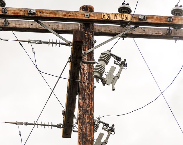
S&C Electric Fault Tamer Fuse Limiter
S&C Electric Fault Tamer
product FEATURES
Fault Tamer provides many features and benefits above those of traditional fuse cutouts and cutouts used in combination with backup current-limiting fuses.
Improved Transformer Protection
- Ideally suited for protecting single- or three-phase transformers through
- 100 kVA single-phase at 15 kV
- 167 kVA single-phase at 25 kV
- Excellent continuous, hot-load pickup, and cold-load pickup capabilities.
- High surge withstand capability. Allows arrester to be mounted on transformer tank without increasing the chance of nuisance operations due to lightning.
Energy Limitation
- Minimizes equipment damage
- Reduces chances of catastrophic transformer failure from internal high-current faults.
- Minimizes bushing and tank damage due to external primary faults.
- Improves service continuity
- Provides complete coordination with upstream lateral fuses.
- Provides complete coordination with substation instantaneous relay settings.
- Enhances power quality
- Minimizes voltage dips that can cause sensitive electronic equipment to shut down.
Operational Characteristics
- Dropout action.
- No parts expelled during circuit interruption.
- Complies with Australian Spark Production Standard AS 1033.1-1990. Ideal for installation in areas prone to grass fires.
Handling Characteristics
- Easy to install/remove using extendo stick. No climbing or bucket truck needed to re-fuse . . . unlike conventional backup current-limiting fuses.
- Retrofits into all vintages of S&C Type XS Fuse Cutouts.
- Operable with Loadbuster®, S&C’s Portable Loadbreak Tool.
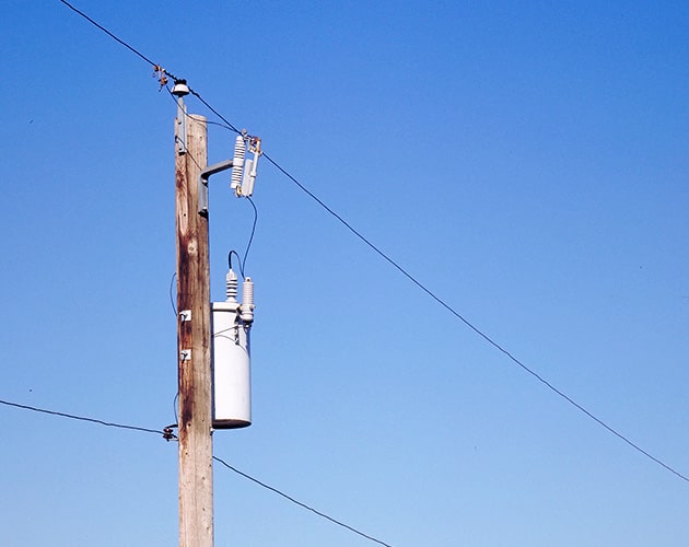
Ratings Data
| 50/60-Hz Ratings | |||||||
| Voltage, kV | Amperes, RMS | ||||||
| System Class, ANSI (IEC) | System Maximum | BIL | Cont. | Interr., Sym. | |||
| 60 Hz | 50 Hz | ||||||
| Three- Phase♠ | Phase-to-Neutral | Three- Phase♠ | Phase-to-Neutral | ||||
| 15 (12) | 15 | 8.7 | 15 | 8.7 | 110 | 20 | 12 000 |
| 15 | 8.7 | 15 | 8.7 | 125 | |||
| 25 (24) | 29 | 16.8 | 26 | 15.1 | 125 | ||
| 29 | 16.8 | 26 | 15.1 | 150 | |||
| 29 | 16.8 | 26 | 15.1 | 150 | |||
| 22/38 (20.8/36) | – | 22 | – | 20.8 | 150 | ||
| ♠ Also applies to phase-to-phase applications. Applications involving single-phase transformers connected phase-to-phase, as well as three-phase applications require the use of a Fault Tamer in each lead. | |||||||
Operation
On low magnitude faults, just the inexpensive fuse cartridge operates — similar to a conventional fuse cutout. Fault Tamer drops open, providing visual indication that it has operated.
On high-magnitude faults, both the fuse cartridge and the backup limiter operate. The fusible element in the limiter melts in multiple locations, creating myriad series arcs that promote an initial rapid increase in arc voltage. The increased arc voltage efficiently limits current to a small fraction of the prospective peak current. Fault current is driven to zero in a controlled fashion, as the fusible element burns back and arc energy is absorbed by the surrounding sand.
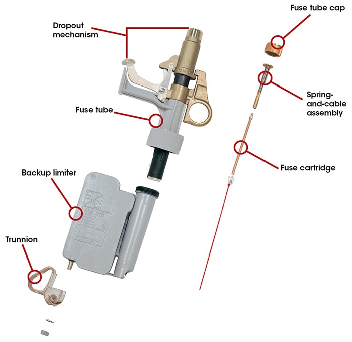
Fault Tamer® Fuse Limiter | Fault Interruption — How It Works
FAULT TAMER FUSE LIMITERS
TIME-CURRENT CHARACTERISTIC (TCC) CURVES
| Curve Type | Ampere Ratings | Fuse Type | TCC Number |
| 15kV to 38kV System Voltages | |||
| Minimum Melting | 3, 5, 7, 10, 15, 20 | Fault Tamer | TCC Number 450-8 |
| Total Clearing | TCC Number 450-8-3 | ||
| S&C Electric Standard Speed (12kV to 22kV System Voltages) | |||
| Minimum Melting | 1, 2, 3, 5, 7, 10, 15, 20 | Fault Tamer | TCC Number 123-8 |
| Total Clearing | TCC Number 123-8-3 | ||
Thorne & Derrick
T&D are Specialist Distributors to UK Distribution Network Operators (DNO’s), NERS Registered Service Providers, ICP’s and HV Jointing Contractors of an extensive range of LV, MV & HV Jointing, Earthing, Substation & Electrical Eqpt – this includes 11kV/33kV/66kV cable joints, terminations and connectors for both DNO and private network applications.
Contact our UK Power Team for competitive quotations, fast delivery from stock and technical support or training on all LV-HV products.
All international sales enquiries can be serviced and supplied by our Export Power Team.
Key Product Categories: Duct Seals | Cable Cleats | Cable Glands | Electrical Safety | Arc Flash Protection | Cable Jointing Tools | Cable Pulling | Earthing | Feeder Pillars | Cable Joints LV | Joints & Terminations MV HV

Cable Scout+ | Easy-fit Cable Rods To Install Cables In A Safe Way
May 4th, 2021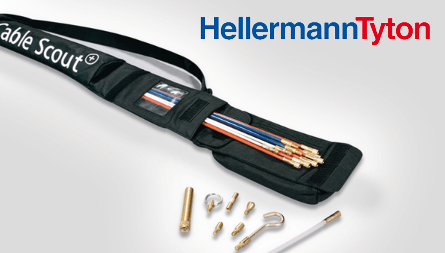
Cable Scout+ Cable Installation System
Cable Scout+
The Hellermann Tyton Cable Scout+ is a professional cable routing tool which enables installers to easily route cables, saving time, even with the most challenging installations and places difficult to access, including:
- in cavities
- through small access holes
- under floor installations
- over suspended ceilings
The Cable Scout+ Cable Installation tools now has an updated design and improved functionality. A remodelled grip allows the cable rods to be easily screwed together – and all components, rods and attachments can be stored in the handy storage and carrying bags. Cable Scout+ is supplied with a range of useful standard accessories. Additional accessories can be purchased separately for pulling cables into commercial and industrial building services applications.
This practical and self-explaining cable installation system facilitates the quick and easy installation of cables over suspended ceilings, behind walls or under floors and many other applications.
Cable Scout+
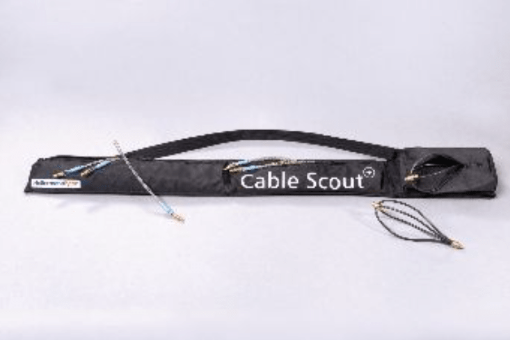
Cable Scout+ Sets
A variety of different sets are available depending on requirements. The cable rods are manufactured from high quality Glass Reinforced Plastic (GRP), which enables a load carrying capacity of up to 200 kg. Cable Scout+ offers a range of features which allows the installer to illuminate, grip, inspect and retrieve by using a range of accessories.
The Cable Scout+ is supplied in a useful durable bag which contains the rods and accessories all in one place.
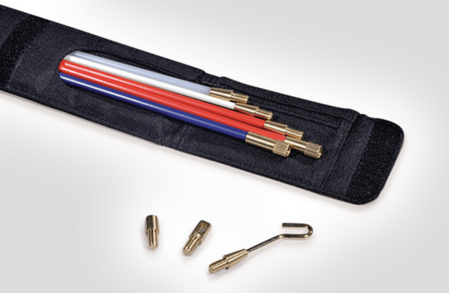
Cable Scout+ Handy Set
The Handy Set is made up for fitting in a tool box.
Contents:
- 1 cable rod x 40 cm (white), 2 cable rods x 40 cm (red), 1 cable rod x 40 cm (blue)
- 40 cm white flexi lead
- Domed bullet
- Mini hook and mini eye
| TYPE | Desc | Content Rods | Rod Capacity | Content Accessories | Article-No. |
| CS-SH | Handy Set | 1 cable rod x 40cm (white) 2 cable rods x 40cm (red) 1 cable rod x 40cm (blue) |
1.6m | 40cm white flexi lead, domed bullet, mini hook, mini eye | 897-90003 |
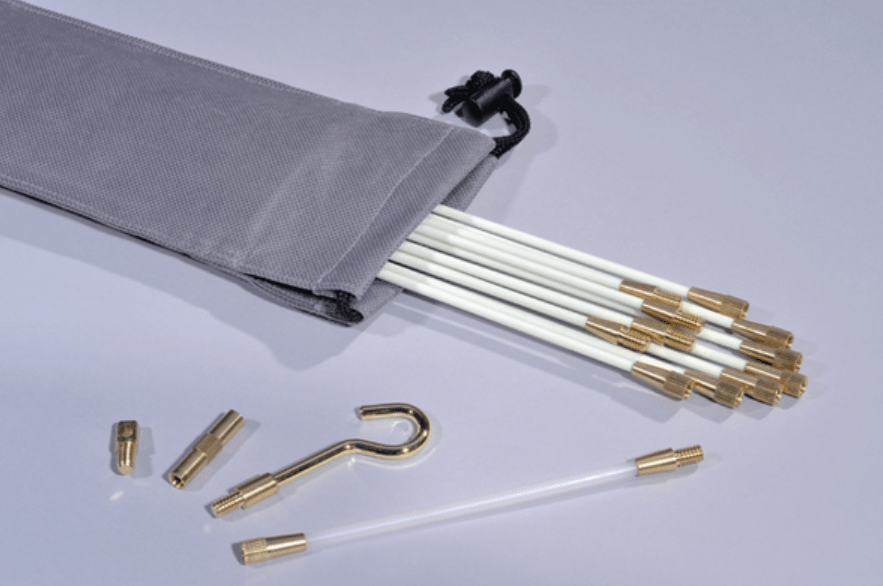 Cable Installation Basic Set
The Basic Set is designed to perform basic cable installation.
Contents:
- 10 rods x 1 m (white), 15 cm white flexi lead
- Gender changer, tuff hook and mini eye
| TYPE | Desc | Content Rods | Rod Capacity | Content Access | Article-No. |
| CS-SB | Basic Set | 10 cable rods x 1m (white) | 10.0m | 15cm white flexi lead, gender changer, tuff hook, mini eye | 897-90000
|
Cable Rod Deluxe SeT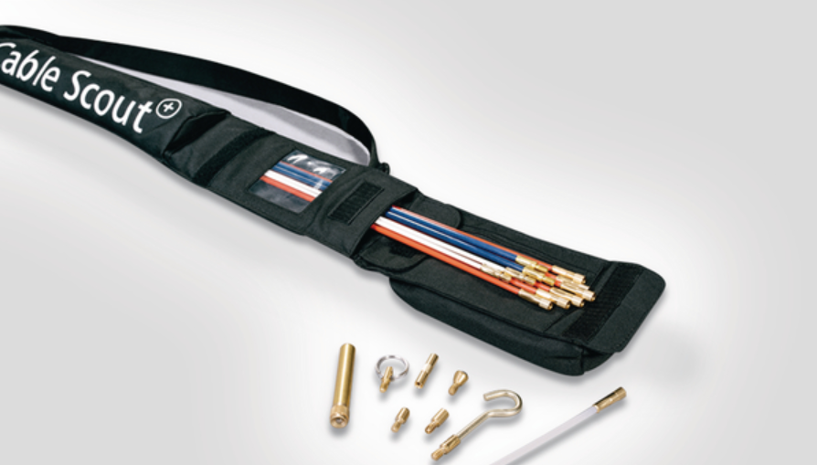
The most comprehensive set is the Deluxe set which is designed for carrying out larger installations.
Contents:
- 2 rods x 1 m (white), 6 rods x 1 m (red), 2 rods x 1 m (blue)
- 15 cm white flexi lead, split ring, gender changer
- Tuff hook, mini eye, domed bullet, flat bullet, beam and single magnet
| TYPE | Desc | Content Rods | Rod Capacity | Content Access | Article-No. |
| CS-SD | Deluxe Set | 2 cable rods x 1m (white) 6 cable rods x 1m (red) 2 cable rods x 1m (blue) |
10.0m | 15cm white flexi lead, split ring, gender changer, tuff hook, mini eye, domed bullet, flat bullet, beam, single magnet | 897-90001 |
Cable Scout+ Accessories
Inspection camera for empty conduits
Cable Scout+cable rods are supplied with a range of useful standard accessories, and additional accessories can be purchased separately.
The high-quality, battery-powered Cable Scout Cam is ideally suited for photo and video recordings in the smallest of spaces. It allows pictures of hidden objects at a distance of up to 10 metres to be captured, e.g. in empty conduits and above suspended ceilings.
The recordings of the inspection camera can be transferred in real time to a smartphone or tablet.
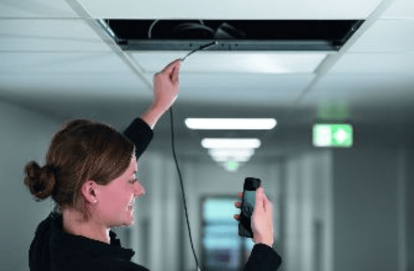 The advantages at a glance:
- Sturdy, high-quality fabrication
- Wireless image and video transmission via WiFi
- Resolution: 2.0 megapixel
- Length: 10 meters
- Splash proof IP68 lens cover
- Dimmable LED light for dark environments
- Free app available for Android and iOS
The package includes an WiFi HD Camera with a 10 meter cable length, a WiFi station with a battery runtime of up to one hour, a USB charging cable, a hook, a magnet, a mirror and a waterproof lens cover.
With its versatile accessories and high-quality manufacturing, Cable Scout Cam is the perfect Cable Scout+ supplement.
Further accessory sets
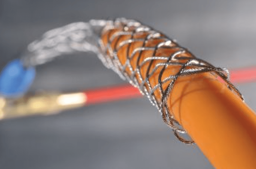
Cable Grips are designed to grip objects and provide reliable and time saving method of securing cables and pipes to the rods. Just open the grip by compressing the braid, push the grip over the cable or pipe and release the grip, which will contract and establish a tight grip on the cable or pipe to the cable rod set.
Available in 5 sizes CS-ACG1630 cable grips suitable for diameters 1.6-3.0cm and CS-ACG0415 cable grips suitable for diameters 0.4-1.5cm
Features and Benefits
Accessory kit CS-SA includes a range of useful tools:
• User can inspect, illuminate and retrieve
• Cable grips allows a very fast way to pull cables
• Whisk glides smoothly over obstacles
• LED Beam brings light into the dark
• Strong magnet lifts metallic tools up to 2.5 kg weight
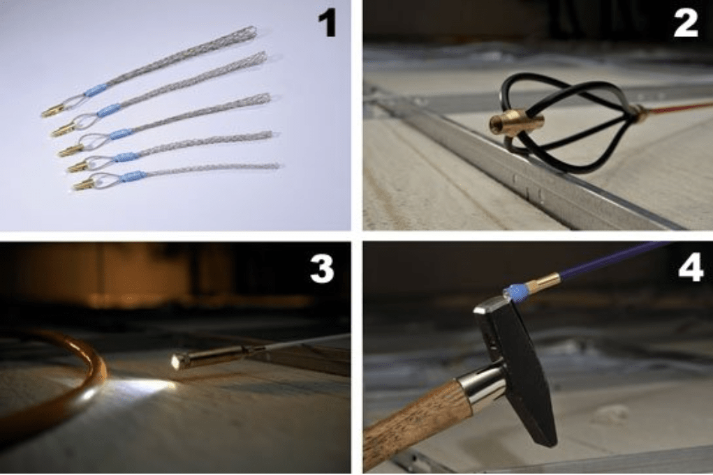
- Cable Grips are available in five different sizes to attach a wide range of cable diameters.
- The whisk allows the rod to glide over obstructions easily.
- The Cable Scout+ Beam – a perfect tool for seeing into cavities.
- The strong magnet lifts a metallic tool of up to 2.5 kg.
| TYPE | Description | Article-No. |
| CS-SA | Accessory Kit: Includes a 15 cm long flexi lead, gender changer, mini hook, tuff hook, mini eye, split ring, round bullet, flat bullet, single magnet, chain |
897-90004 |
| CS-ACG1630 | Cable Grip: Suitable for diameter 1.6 – 3.0 cm | 897-90027 |
| CS-ACG0415 | Cable grips: Suitable for diameters 0.4 – 1.5 cm | 897-90026 |
| CS-AW | Whisk: Enables cables to glide over rough and uneven surfaces. | 897-90018 |
| CS-AB | Beam: Useful for inspection purposes in dark surroundings. | 897-90016 |
| CS-AMG2 | Strong Magnet: A helpful tool to lift metal tools with up to 2.5 kg weight | 897-90015 |
Cable Scout+ Cable Rod Sets
The flexible cable rods made of glass-reinforced plastic (GRP) are simply screwed together and fitted with clever attachments. Three diameters and different bending radii guarantee high flexibility at work. The rods can be bent, pushed or pulled and bear cable weight even up to 200 kg.
Cable rod selection
| TYPE | Content Rods | Flexibility | Ø D | Article-No. |
| CS-P6 | One pair of 1 m blue cable rods | strong | 6.0 | 897-90007 |
| CS-PN | One pair of 1 m nylon cable rods | fully flexible | 5.0 | 897-90008 |
| CS-P5 | One pair of 1 m red cable rods | medium | 5.0 | 897-90006 |
| CS-P4 | One pair of 1 m white cable rods | flexible | 4.0 | 897-90005 |
Further Reading
THORNE & DERRICK
Thorne & Derrick are national distributors of LV, MV & HV Cable Installation, Jointing, Substation & Electrical Equipment – servicing businesses involved in cabling, jointing, substation, earthing, overhead line and electrical construction at LV, 11kV, 33kV, 66kV and EHV. Supplying a complete range of power cable accessories to support the installation and maintenance of low/medium and high voltage power systems:
- Slip-on Cable Terminations
- Cold-shrink Cable Terminations
- Heat-shrink Cable Terminations
- Cable Joints – Heat & Cold-shrink
- Separable Connectors (Euromold)
- Surge Arresters & Switchgear/Transformer Bushings
Key Product Categories: Duct Seals | Cable Cleats | Cable Glands | Electrical Safety | Arc Flash Protection | Cable Jointing Tools | Cable Pulling | Earthing | Feeder Pillars | Cable Joints LV | Joints & Terminations MV
Hellermann Tyton Pressgel | Silicone Gel for the Protection of Junction Boxes & Electronic Components
May 4th, 2021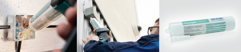
Insulation & Sealing of Cable Connections in Junction Boxes
Hellermann Tyton Pressgel
Silicone Gel for the Protection of Electrical Installations
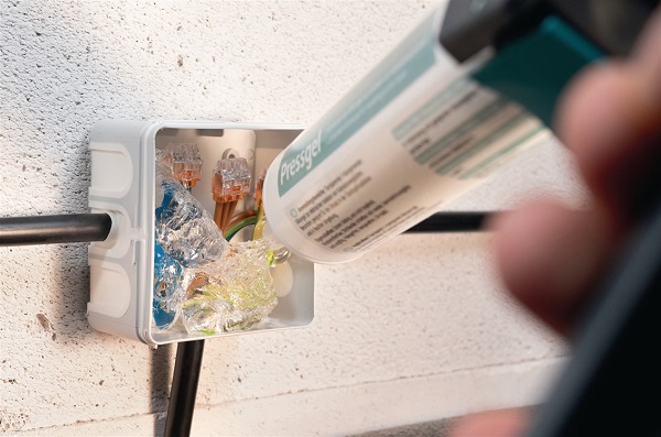
Pressgel from Hellermann Tyton is the ideal solution for insulation and sealing of cable connections in junction boxes. Due to its protective properties it prevents corrosion and oxidation. The Hellermann Tyton Pressgel is particularly suitable for use in overhead installations and in damp or humid environments – for electrical installation up to 1kV.
Currently, electrical connections, inside empty enclosures or junction boxes are exposed to the risk of short circuit, oxidation and corrosion, which may over time cause irreparable damages. By using PressGel this can prevent many of the environmental hazards such as vibration, water ingress, insects and dust which can result in installation failures.
PressGel covers a range of applications from DIY projects such as protecting CCTV cameras or outdoor lighting from insects and/or rain to industrial applications such as mining, where an IP68 rating is required to protect electrical installations.
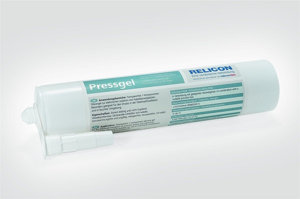
Hellermann Tyton Pressgel
Pressgel Features & Benefits
- Ready to use transparent Silicon gel in cartridge gun
- Highly adhesive and non-drip
- IP 68 in combination with appropriate junction box
- Keeps insects away from electrical installations
- Self-sealing for cables
- Removable cable sealing product
- Re-closable cartridge for multiple use
- Non-toxic
- Halogen-free
- Isocyanate-free
- UV-stable
Silicone Gel Material & Specifications
| Dielectric Strength | >20 kV/mm |
| ELV compliant (Article 4 – 2) | YES |
| Halogenfree | Yes |
| Hazardous good | No |
| Material | Silicone (SI) |
| Operating Temperature – °C | -60 °C to +200 °C |
| Shelf Life | Unlimited |
| Specifications | HF RoHS |
| Vibrations absorbing | Yes |
Pressgel Technical Data
| Application Tool | PTS4, ASS103, RCS0425 |
| Colour | Transparent (CL) |
| Pack Cont. | 310ml |
| Package Quantity per | pcs. |
| PART DESCRIPTION | Pressgel-SI-CL |
| Product Family | Relicon 1-component sillicone gel |
| Product Group | 1-component sillicone gel |
| Removable | Yes |
| Short Description | 1-component sillicone gel |
| Variant | Gel |
| Viscosity | 3000 mPa*s, 23 °C (EN ISO 2555) |
Hellermann Tyton are manufacturers of cable management accessories for fastening, fixing and identifying cables. With over 60,000 products, the range includes nylon cable ties, stainless steel cable ties, heat shrink moulded shapes, electrical enclosures, tapes, cable boots and labelling systems for cables.

T&D – Main UK Hellermann Tyton Distributor
THORNE & DERRICK
Thorne & Derrick are national distributors of LV, MV & HV Cable Installation, Jointing, Substation & Electrical Equipment – servicing businesses involved in cabling, jointing, substation, earthing, overhead line and electrical construction at LV, 11kV, 33kV, 66kV and EHV. Supplying a complete range of power cable accessories to support the installation and maintenance of low/medium and high voltage power systems:
- Slip-on Cable Terminations
- Cold-shrink Cable Terminations
- Heat-shrink Cable Terminations
- Cable Joints – Heat & Cold-shrink
- Separable Connectors (Euromold)
- Surge Arresters & Switchgear/Transformer Bushings
Key Product Categories: Duct Seals | Cable Cleats | Cable Glands | Electrical Safety | Arc Flash Protection | Cable Jointing Tools | Cable Pulling | Earthing | Feeder Pillars | Cable Joints LV | Joints & Terminations MV HV
The 5 Factors To Assessing Cable Splice Life Expectancy
May 4th, 2021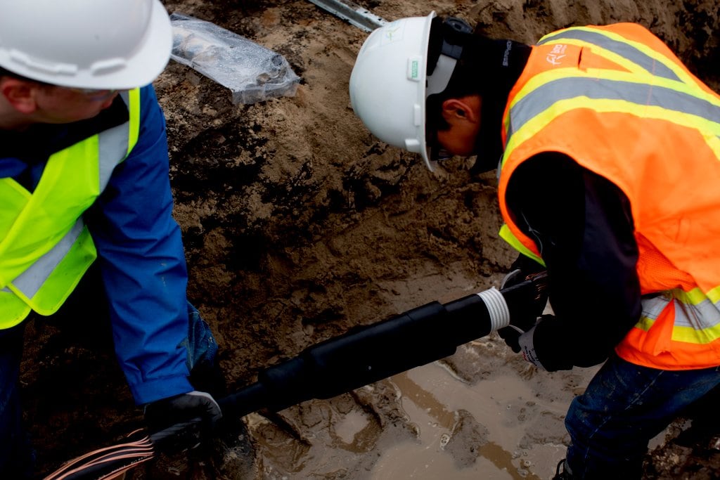
Cable Splicing
Assessing Life Expectancy
Guest Article | 3M Electrical Canada
Thorne & Derrick Stockists & Distributors for 3M Electrical Since 1985
Scotchcast, Scotch & ColdShrink Joints, Terminations up to 66kV Ex Stock
Cable splice failures are expensive, so just imagine the dire consequences of a power failure leaving over 700,000 customers without power. Many of us in Ontario can still recall the shock of the 2003 Northeast Blackout.
As a consumer of electricity our expectation is that our lights stay on, our fridges stay cold, and our roads stay safe with operating traffic lights. When the lights go out, utilities have the extensive task of finding the source of the electrical or power cable fault, communicating with public and customers, and taking on the cost of repair including labour costs.
How do utilities actively try to prevent electrical failures?
Utilities measure system average interruption duration index (SAIDI) and customer average interruption duration index (CAIFI) as both of these are negatively impacted by underground cable splices and their failures. They are constantly looking for ways to help improve these measurements – and improvement comes down to choosing safe and reliable MV Cable Accessories.
Identifying this need within the utility industry, I created a Whitepaper that evaluates the five critical factors to help determine the overall life expectancy of a cable splice. I did this by leveraging 3M Cold Shrink QS-III’s 23 years of field experience.
➡ Did you know: Some of the 3M Cold Shrink Products installed in the field are still operational after almost 50 years!
The goal of this study is to help provide utilities with research and insights to help improve their SAIDI and CAIFI measurements.
Study highlight: 5 factors to help determine the life expectancy of an electrical Cable splice
- Technology: Reliability of an electrical cable splice hinges on your ability to maintain radial splice pressure on the cables. 3M™ Cold Shrink QS-III is equipped with 3M™ Cold Shrink Technology, which retains radial pressure over the life of the cable splice. As a result, there is no loss of pressure with heat cycling.
- Materials: Elasticity and the capability to apply in cold environments (especially in Canada’s frigid winters) are critical. 3M™ Cold Shrink QS-III’s silicone rubber is an excellent material choice for splicing applications. It acts as a “living seal” – helping provide long-term elasticity (including at negative temperatures) and has great electrical properties required by a robust splice design. Additionally, we use silicone rubber filled with thermally conductive additives to help improve heat dissipating properties of the splice body.
- Design: An electrical cable splice or cable joint must be designed to manage electrical stresses by minimizing them for increased long-term performance. 3M™ Cold Shrink QS-III’s moulded splice body exhibits design features that lower electrical stresses. The features include large electrical geometric stress cones, rounded semi-conductive electrodes with an undercut insulation that lower stresses at cable/splice interface and additional insulation thickness at the end of the inner electrode to compensate for increased stresses in this area.
- Workmanship: Workmanship in splice installation and cable preparation have a great impact in long-term performance. A clear majority of cable failure investigations that I’ve run for our customers pinpoint poor workmanship in cable preparation techniques as the leading root cause for failures. Some of the negative impacts of inconsistent cable preparation and/or cable cleaning that increase electrical stresses can be mitigated by design features such as the rounded semi-conductive electrode with an undercut of insulation that lowers stresses in the area of the splice/cable interface. 3M™ Cold Shrink QS-III is designed to help mitigate these cable preparation errors and the moulded electrical splice body offers ease of installation and high quality.
- Testing Procedures: A product that is designed and tested at levels meeting and exceeding industry standards will have an adequate long-term performance. For 3M™ Cold Shrink QS-III qualification testing, we rate our electrical splices one basic insulation level (BIL) level higher than the corresponding splice classification (ex. 15kV splices meet the BIL requirements of a 25kV splice).

Further Reading
- Cable Terminations | Cold Shrink Terminations MV HV Cables
- 3M Cold Shrink Terminations Connecting Nexans 12kV (MV) Cable Onto Busbar
- 66kV Terminations | NEW Stock Introduction for 3M Cold Shrink Cable Terminations
- 3M Terminations | Surface Tracking on Medium Voltage Cable Terminations by 3M

THORNE & DERRICK
T&D are Specialist Distributors to UK Distribution Network Operators (DNO’s), NERS Registered Service Providers, ICP’s and HV Jointing Contractors of an extensive range of LV, MV & HV Jointing, Earthing, Substation & Electrical Equipment – this includes 11kV/33kV/66kV joints, terminations and connectors for both DNO and private network applications.
Contact our UK Power Team for competitive quotations, fast delivery from stock and technical support or training on all LV-HV products.
Key Product Categories: Duct Seals | Cable Cleats | Cable Glands | Electrical Safety | Arc Flash Protection | Cable Jointing Tools | Cable Pulling | Earthing | Feeder Pillars | Cable Joints LV | Joints & Terminations MV HV

High Voltage Cable Cleats | Cables, Tunnels & Supporting HV Cables
May 4th, 2021
High Voltage Cable Cleats (HV EHV 132kV 275kV 400kV Cables) – Ellis Patents Centaur
High Voltage Cable Tunnel Cleats
275-400kV
As a result of the increasingly congested and over populated nature of our major cities, high voltage cable tunnels are fast becoming the preferred option for delivering electrical power – most notably because they provide a means of carrying large HV cables in a non-intrusive manner.
Andy Booth, Business Development Manager of leading cable cleat manufacturer, Ellis Patents talks to Electrical Review about a paper the company co-presented at the recent CIGRE Session in Paris, which focused on the issues concerning the clamping and supporting of HV cable systems in underground cable tunnels.
Many of the leading utilities companies are currently investing heavily in HV cable tunnels, and to give some idea of the scale of this investment it’s worth highlighting some of the proposed cable tunnels in London are 3m in diameter and up to 25km long.
Furthermore, the level of investment in new HV cable installations is likely to grow substantially over the next few years due to the fact many of the UK’s existing fluid filled 275kV and 400kV HV cable circuits are reaching the end of their original design life and will need to be replaced with new XLPE circuits.
As a rule of thumb, these HV single core cable systems are installed in a vertical flexible arrangement. This means the cables are supported, generally by cable cleats, at intervals of between 5 and 8.5 metres and allowed to sag in between.
This cable sagging allows the cables to take up thermal expansion and contraction in steady state conditions without the exertion of large thermo-mechanical forces. During load cycles the thermo-mechanical thrust developed by the cable conductor and sheath in an axial direction needs to be constrained by the cable cleats without damaging the cable oversheath.
In the case of short circuit faults and lightning strikes, the resulting high fault currents flowing through the cable will result in large lateral electro-mechanical forces between cores, which cause the cables to shake violently.
During these conditions accelerated sidewall pressures are experienced on the cable at the fixing points, which can compromise the integrity of not just the cleats, supports, clamps and the cable, but the entire HV cable network.
Amazingly, and despite the huge amount of theories, standards and literature regarding fault protection, very little attention is given to arguably the single most important piece of equipment in any fault protection system – the cable cleat.
Yes, IEC61914:2009 describes the appropriate requirements for cable cleats for electrical installations, but this only allows the use of 600V – 1kV cables in a series of tests to confirm the resistance to electro-magnetic forces.
Until now, methods for supporting large HV cables at fixed points have been designed on a project by project basis, but there have been no tests or related publications to determine how these HV cable fixings should perform in the event of a fault. Therefore, our intention when starting work on this project was simple – we wanted to develop a standard product that would provide adequate fault protection for all HV cable installations.
Rationale for appropriate fixings for power cable systems
The operating time for a typical breaker is generally between 3 and 5 cycles, which is equivalent to 0.06 – 0.1 seconds on a 50Hz system. Exceptionally quick relays may operate at 1.5 cycles. However, when considering three-phase faults and the instance of the peak forces, the time frame will be a quarter of a cycle or 0.005 seconds.
On the occurrence of a fault the highest repulsive force is proportional to the square of the peak short circuit current. This is then followed by a residual, pulsating, oscillating stress at a frequency of twice the operating frequency, known as the fault RMS. However, it is accepted that the forces at the peak of the fault are the highest, the most instantaneous, and in turn the most destructive, when considering system protection.
Recommendations for the calculation of short circuit currents are given in the IEC 60909:2001 series. For three phase short circuit faults the most severe repulsive force for flat spaced (horizontally or vertically) cables is experienced in the central phase due to the oscillating effects of mutually induced forces by the outside phases. For trefoil installed cables an equal force (at peak) is experienced in all three phases due to the symmetry.
Further consideration should also be given to the linear stresses along the actual conductor. It is common with cable installation assessments to use the calculation method simulating a bar fixed at both ends, thus determining the transverse deflection rate due to electro-magnetic forces during a fault. Further consideration, as a result of the instantaneous forces during a fault, is the effect of the surface pressure from the moving cables and its effect on the inner loop of the cleat itself.
The time duration for short circuit faults, such as 1 or 3 seconds, which is often specified by clients or in installation specifications, is often misinterpreted with respect to the duration of an actual short circuit fault. The 1s or 3s requirement quoted is the thermal withstand characteristic of the cable and considers conductor cross section and its ability to carry a level of current and therefore heat.
Design Criteria for HV Cable Saddles and Cable Straps
A longitudinal ‘saddle’ type of design, rather than the traditional cable clamp design tends to be best suited to this type of installations. Firstly, the cable saddle should be able to support the weight of the cable in its final installed position – and remember a 2500mm² copper conductor, lead sheathed cable can weigh almost 50kg per metre.
If we assume an 8m fixing distance, then the cable saddle must be able to support 4m (200kg) on one side and 4m on the other side, without deflecting or changing its original profile. Furthermore, the longitudinal saddle must also be radiused along its length to ensure the cable is adequately and safely supported. Various cable construction types affect the radius of the installed cables. For example a lead sheathed, copper conductor cable will have considerably different characteristics to an aluminium sheathed, aluminium conductor cable. The saddle manufacturer must ensure their product design matches this specific cable sag radius on any particular project.
It is undesirable for a cable to be in contact with any sharp edge of a cable cleat. To alleviate the problems various steps can be taken: All sharp edges must be removed as a matter of course from any face which may come into contact with the cable, either during installation, or when the cable is in its final, fixed position.
Generally, the base portion of the cable saddle for this type of installation is a minimum of 600mm long. As the cable is installed over the top of this 600mm long ‘beam’ it becomes curved when sagged. It is essential that the 600mm long ‘base section’ is also curved along its entire length, to ensure support is given to the cable over an area which is as large as possible. On each end of this curved ‘saddle’ section, as the cable leaves the saddle, an additional ‘flare’ should be added to further reduce the possibility of the cable being in contact with a defined edge, and therefore becoming damaged.
Once these general rules have been applied to an initial cleat concept, the actual cleat spacing and installation sag can be calculated.
Short Circuit Testing of a HV Cable Saddle Installation
There is very little empirical research, or cited publications with regard to short circuit testing cable fixings for HV cables. That said, major utility groups around the world use National Grid in the UK for technical expertise and knowledge and so it seemed sensible to use the technical specifications of National Grid as the basis for a series of live short circuit tests.
These tests were carried out at KEMA, an internationally recognised testing station in The Netherlands. The design of the test rig corresponded to the worst case scenario for the peak forces, and 8.4m fixing centres and a phase to phase spacing of 500mm was selected. If the calculation methods from IEC 61914:2009 are employed the maximum theoretical forces between each cleat can be shown as follows:
For a 2 phase fault:
F = 0.2 x 157.5² = 9922.5N/m or 9.923kN/m
0.5
The figure of 157.5 was obtained by using a multiplication factor of 2.5 on a 63kA RMS. This was the theoretical calculation used to obtain the appropriate peak force levels of the fault.
Post Test Cable Examinations
Immediately after the tests were completed and the cables were still in position, an electrical test was performed on each individual cable. Each cable sample satisfactorily withstood a 5kV direct voltage, applied between the lead sheath and the earthed conductive screen for one minute without breakdown or incident.
This procedure follows the requirements of ENA C55/4.
Upon dismantling the test rig a 1m section of cable was identified adjacent to each saddle and each intermediate strap (500mm each side of the saddle or clamp), and cut away for later examination. For each 1m length the following aspects were examined in great detail: Outer jacket over sheath, lead sheath, copper wire screen, lead sheath, and the interior surface core screen.
There were no features or defects attributable to the cleats or intermediate straps. Some features attributable to manufacturing and/or handling of the cable were seen, but as they were independent of the position of the cable cleats, it was evident that they were not due to the presence of the cleats. In any case these features were not of such a severity to compromise the performance of the cable.
Conclusion
With HV power cable installations becoming ever more commonplace, it was absolutely imperative that a tried, tested and trusted means of ensuring these cables remain intact and working during a short circuit situation was available to the industry. The Centaur saddle cleat that we developed as a result of this research has certainly been enthusiastically welcomed and is currently being installed in a major HV cable installation in the UK.
That said, from an industry perspective, there is still a long way to go. It seems that every new type of HV cable and accessory seems to be tested to a known standard with the exception of the cable cleat. However, now that a precedence has been set by our research and development it should follow that every cable saddle, cleat, strap or clamp that is to be used on a flexibly installed, HV, underground system should be fully and independently tested to meet, or exceed, the requirements of the specific project. Furthermore, all engineers in the field need to become ever more aware of the importance of cable fixings.
A full copy of the CIGRE session paper is available upon request.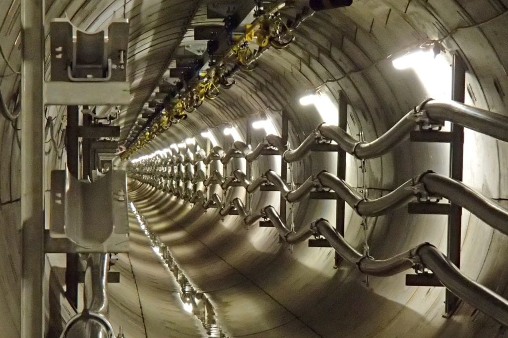
Thorne & Derrick
T&D are Specialist Distributors to UK Distribution Network Operators (DNO’s), NERS Registered Service Providers, ICP’s and HV Jointing Contractors of an extensive range of LV, MV & HV Jointing, Earthing, Substation & Electrical Eqpt – this includes 11kV/33kV/66kV joints, terminations and connectors for both DNO and private network applications.
Contact our UK Power Team for competitive quotations, fast delivery from stock and technical support or training on all LV-HV products.
Key Product Categories: Duct Seals | Cable Cleats | Cable Glands | Electrical Safety | Arc Flash Protection | Cable Jointing Tools | Cable Pulling | Earthing | Feeder Pillars | Cable Joints LV | Joints & Terminations MV HV
➡ Read: Thorne & Derrick Announce Distribution Agreement & Contract With Nexans


