

Blog
Subsea Power Cables in Shallow Water | DNVGL-RP-0360
August 6th, 2021
This Document supersedes DNV-RP-J301, February 2014.
Thorne & Derrick can provide Joints, Terminations & Connectors for the safe and reliable operation of subsea power cable systems up to 66kV – this includes cable accessories utilising Heat Shrink, Cold Shrink and EPDM Rubber type connection and termination products from market-leading manufacturers including 3M Electrical, Pfisterer CONNEX, Nexans Euromold and NKT.
Further Reading
- Cable Grips | Supporting Inter-array, Export, Umbilical & Subsea Cable Installations
- Nexans Subsea Solutions For Power Networks
- How To Install A Subsea Cable – Power Networks
- How To Remove Bitumen From Subsea Cables & Umbilicals Using Socomore Wipes
- Avoiding Subsea Cable Failures Before They Hit The Water
- Subsea Power Cables For North Sea Link Interconnector Project

Thorne & Derrick are Specialist Distributors to the UK and international Offshore Wind & Renewable industry to provide safe and reliable LV HV Electrical Cable & Power Distribution Systems up to 66kV – we are highly customer responsive and absolutely committed to providing a world-class service.
Contact our UK Power Team for competitive quotations, fast delivery from stock and technical support or training on all LV-HV products.
Key Product Categories: Duct Seals | Cable Cleats | Cable Glands | Electrical Safety | Arc Flash Protection | Cable Jointing Tools | Cable Pulling | Earthing | Feeder Pillars | Cable Joints LV | Joints & Terminations MV HV

See how T&D support, supply and service the Renewable Energy industry.

MV HV Cables 11kV 33kV 66kV | Cable Joints, Terminations & Connections
CLAIM FREE VOUCHERS | Arc Flash & Electrical Safety Programme
August 6th, 2021
EPSCO’s groundbreaking OneMoment online electrical safety training series is going to change the way you see safety courses, forever.
The experienced professionals at EPSCO set out to do much more than rehash the safety manuals and government regulations. They put together a team of electrical safety experts, accident survivors, storytelling professionals, and talented presenters to create courses that are dynamic, engaging, easy to understand, and tested in real-life situations.
EPSCO produced OneMoment from a Safety Manager’s perspective, with best practices that will fit in to the routines every member of your team is already doing.
OneMoment is designed with custom modules that benefit everyone at your facility, including engineers, managers, safety personnel, qualified workers, and unqualified workers too.
OneMoment covers a range of topics starting with the basics of electrical shock, hazards, and risk prevention, then moving on to advanced topics like arc flash, maintenance, and pre/post job planning.
OneMoment online electrical safety training brings EPSCO’s years of experience in the field to your team. Click to sign up today for the most comprehensive and compelling safety course out there.
➡ We have 10 FREE VOUCHERS to giveaway – to qualify you must take a moment to Follow our LinkedIn Company Page.
Introducing Electrical Power & Safety Company 
Delivering outstanding products and services for electrical power systems. EPSCO specialize in performing Arc Flash Analysis of your facility and training your team to deal with this danger in the safest manner possible. Let us help you keep your people SAFE! Electrical Power & Safety Company is an industry leader in providing responsive, flexible, and reliable service for the industrial, construction, and mining industries. EPSCO goal is to provide each and every one of our clients with the solutions needed to efficiently and effectively manage internal power needs.
EPSCO began in 2008 as Electrical Power Solutions Inc which was a body of project managers relaying customer’s project needs to contractors versed in fulfilling their requirements. Today, EPSCO has expanded and provides direct onsite services, and employs a proficient and knowledgeable team of Professional Engineers, Project Managers, Field Service Technicians, and Control/Automation Specialists. Allow the EPSCO team to provide you with the electrical power and safety solutions you need to maintain a competitive edge in a constantly evolving industrial market.

Cut Outs & Isolators | The Street Weapon In Street Lighting Safety by Lucy Zodion
August 4th, 2021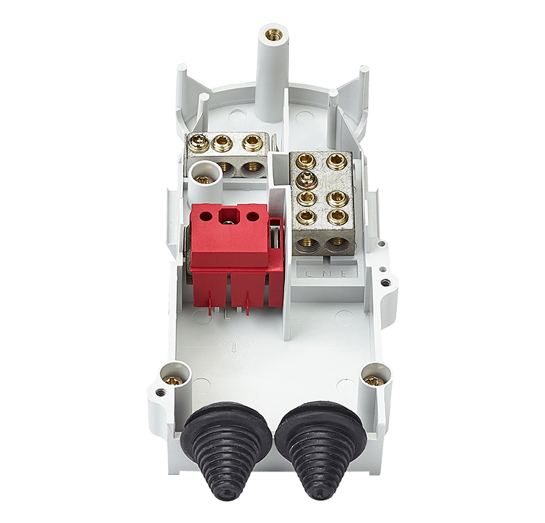
Street Lighting Safety
Cut Outs & Isolators
An industry leader in the design and development of street lighting control products, Lucy Zodion offers a range of solutions that span from the ground up; encompassing in-ground feeder pillars right through to cloud based IoT street lighting management. In the Highways industry, one of the key ranges Lucy Zodion offers is fused products.
Fused products or cut-outs and isolators have an important job that is often taken for granted – they terminate a supply cable and provide electrical protection for the light on the column, improving safety for those maintaining and upgrading lamp post infrastructure.
Greater awareness of safety & quality
Lucy Zodion understands that certain measures and standards should be met in order to ensure the safety of street lighting columns, where the independent testing of fused products contributes to their suitability in the field. From the materials such products are made with, to the way they are engineered to function, all are considerations before they can be used and installed.
The quality and manufacture of fused products contribute to their safety and reliability in the field. This is something that carries great impetus and should be understood by all in the industry. This paper explores what is currently known about fused products (from a manufacturing point of view) and the quality measures that are currently in place, to assure safety and quality.
What we know
British Standards
To comply with a British Standard indicates that a company/organisation takes its responsibilities seriously; compliance is often taken as evidence of due diligence.
By following the processes recommended in a Standard, it implies that impetus is made on doing things properly. It is important to highlight that standards aren’t the same as regulations; following a standard doesn’t guarantee that the relevant laws are met, due to the fact that legislation could change within the lifetime of the Standard. But, companies that follow the standard give customers and collaborators confidence that measures are being taken to provide a high level of quality in the products they produce.
In respect of the context of this paper, reference is made to the BS 7654 Standard, which is for single phase street lighting cut-out assemblies for low-voltage public electricity distribution systems – 25A rating for highway power supplies and street furniture. This is a standard which covers the whole of the product and not just parts. From constructional and performance requirements, normal service and mounting conditions over all sizes, the Standard requires the designed unit to pass the tests prescribed within it. This is to ensure firstly that the unit is safe.
A large part of the Standard is the type testing that the designed unit has to pass; these tests will prove that the unit will be fit for purpose in service.
Such tests include:
Terminal Torque Test
This is a test which proves that terminals have the strength to be tightened to a given torque onto a copper rod, for a period of one hour and to show no signs of cracking or distortion; thus proving its durability in the field.
In regards to the material /design of the terminal – it states which material cannot be used, to the minimum amount of threads (all screw holes with pinching screws shell contain at least three full threads conforming to BS 3643).
In reference to the design of the unit – a simple part of the Standard gives the layout of the terminals, stating that Phase Neutral and earth shall be positioned from left to right and viewed from the front, so that an operative will instinctively know their way around the cut out unit.
Where the standard does not cover the requirement in full, it will refer to other standards that will. This Standard also covers the IP levels required (IP22), again safeguarding the operative material choice is one area which is heavily scrutinized by the standard – this is covered by several tests:
Impact Test
This prescribes how the test is to be carried out. Impact energy of 0.25J, 2 Sets of units (6 in each); Test 1 at room temperature and Test 2 after the units have been at a temperature of -25°C for a period of not less than 18 hours, and is struck the amount of times as prescribed in the standard (three times).
This will prove the suitability of the given material and design; it proves both its durability and that the given materials will not shatter and expose dangerous parts. Clearances and creepage distances are also stated and are to be a minimum of 6mm.
The flammability test should be in accordance with BSEN 60695-11-10 test method A, which is a horizontal burn test.
Hot Ball Test
This is when a piece of apparatus with a 5mm diameter ball is pressed against the material surface with a force of 20N. and placed into a heating cabinet; this can be at different temperatures depending what the material is specified for:
- 125°C for insulating materials which retain current carrying parts,
- 70°C for other insulating material not necessary to retain current carrying parts in position
After a period of 1 hour, the test material is immersed in cold water at which point the diameter of the impression by the ball shall be measured.
Resistance to Tracking
This tests the material which in itself involves a series of tests, carried out in accordance to the Standard BS EN 60112.
In principle, this test requires the upper surface of the test specimen to be supported in an approximately horizontal plane and subjected to an electrical stress via two electrodes. The surface between the electrodes is subjected to a succession of drops of electrolyte, either until the overcurrent device operates, or until a persistent flame occurs, or until the test period has elapsed.
The individual tests are of short duration (less than 1 h) with up to 50 or 100 drops of about 20mg of electrolyte falling at 30 second intervals between platinum electrodes, 4mm apart on the test specimen surface. An AC voltage between 100 V and 600 V is applied to the electrodes during the test, where specimens may also erode or soften, thereby allowing the electrodes to penetrate them.
Resistance tracking is an important part of the testing process and pins down the characteristics of the materials used, as well as their ability to withstand environments similar to those in the field. Without such testing and the supporting certification, safety and performance cannot be assured.
Type Test
One of the main parts of the type test is the section on the performance side. These tests are designed to test the units in operation, temperature rise testing at maximum rating. Temperature rise test is when the unit is loaded to the maximum of 25A and is left on until it reaches a stable state; testing that the temperature limits stated for this test are not exceeded.
Cyclic loading of the unit puts the unit on test for 1h on/1h off, for a period 2000 cycles. At every 100 cycles a standard temperature rise test is carried out (this test alone can take approximately 6 months to carry out).
The BS 7654 Standard is extensive and the above information is not exhaustive of its entirety, however highlights the attention to detail that is required in certain aspects of the Standard.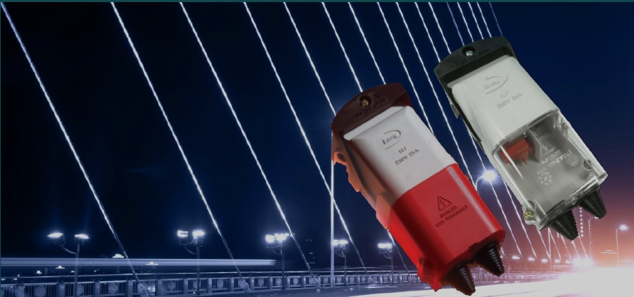
Cut outs
Cut outs are needed in every Distribution Network Operator (DNO) supplied streetlight in the UK. A cut out has its own British Standard, BS 7654 (as detailed above), which covers all aspects of the cut out from the materials it’s manufactured from to a series of tests relating to temperature, ingress protection, current, mechanical strength; it even states its physical size. Manufacturers must be able to prove this with an independent certification and this is something that those buying the product should always ask for.
The cut out comes with a set of terminal blocks, designed to accept cables up to 25mm² and has a suite of accessories that include extension pieces, brass and plastic cable entry plates, to suit different types of cable and to make installation as easy as possible.
The fuse in the cut out is contained within the cover of the unit, the action of removing this cover disconnects the fuse (so it can be replaced) which also isolates the load from the supply. Higher quality cut out designs (such as Lucy Zodion models) have a lever cam action handle on the cover, which improves operator access to cables. Although the terminals are isolated, removing a cover from a cut-out to change the fuse should be done in a safe and responsible manner that complies with the responsibilities under organisation and legislative policies.
Cut outs only come in either a single or twin fuse version; the option of using digital timers or RCCD’s to control or give additional protection aren’t covered by the Standard.

Lucy Zodion Electric Vehicle Power Supply Feeder Pillars for EV Charge Points
Isolators
Isolators are used for secondary isolation and add an extra layer of electrical safety; they are not required in all street lighting columns, unlike cut outs. The main body or casing of an isolator isn’t covered by the same BS as a cut out, however there are other British Standards that relate to them, which the switch and fuse carriers must meet (BS88). To assure quality, manufacturers should produce the body to the relevant BS for isolators (BS EN 60947-3:2009+A2:2015 and BS7671) and independent certification should be available.
The isolator provides a switch-disconnector which can be operated in order to isolate the load, allowing maintenance and for the fuse to be replaced. This makes changing fuses and isolating circuits simple and helps prevent risks of injury. Additionally, to increase safety, covers can be made lockable. Most isolators have an interlock device that automatically slides over the fuse carrier(s) when the isolator is moved to the ON position, ensuring that a fuse carrier cannot be opened with the circuit energised.
Both isolators and fuse carriers should be independently tested by a third party, in KEMA laboratories or the equivalent, to meet the relevant Standards. Factors like a high tracking index and self extinguishing plastics are vitally important when it comes to safety. Using robust and durable thermoplastic enclosures with high anti-tracking properties, well manufactured isolators often have a safe and transparent front access cover to offer clear visibility, reducing the need to open up the isolator.
Typically, the isolator comes with a 32 amp isolator and a fuse carrier, however, if the product has a DIN rail different arrangements and components can be used, e.g. digital timers, MCB’s, RCBO’s, RCCB’s, contactors, push buttons, etc. An isolator can form the basis of a unit used for Festive Decorations, for example.
The isolator usually has a DIN rail that can accept products like MCB’s and fuse carriers, which have a total of four modules in width, or less; however they are available with a capacity of more than four if required. Should the isolator include a DIN rail, a module with no more than 17.5mm width is to be used, almost like a mini distribution board.
The isolator typically has a suite of accessories that include extension pieces, brass and plastic cable entry plates to suit different types of cable and to make installation as easy as possible. Something the installer should consider is that terminal blocks sometimes need to be added to the final assembly to aid installation; this, in some instances, makes it quite long in length.

Street Lighting Isolators – Trojan Double Pole Cut Outs 32A – Lucy Zodion
Lucy Zodion Fused Products
The Lucy Zodion range of fused products follows the requirements under the respective Standards highlighted in this document. With an in-house Quality Team, it means that products can be tested at every stage of assembly – from initial design to completion – implying due diligence throughout each step of the manufacture process.
Additionally, each of Lucy Zodion’s products is independently tested by a third party, in KEMA laboratories, to ensure such measures meet industry Standards. As a responsible company Lucy Zodion has its own Quality Policy that covers operations throughout the whole company, as well as the manufacture of street lighting and power distribution products. It provides the approach necessary to ensure the requirements of ISO 9001:2015, and any regulatory/statutory requirements, are achieved in full and are improved where possible to ensure that customer requirements are met in full by the business.
Should Lucy Zodion customers wish view certification relevant to any aspect of the Standards and Policies stated above, Lucy Zodion is obliged to share and confirm the responsible steps have been taken to assure quality and safety.

Thorne & Derrick distribute an extensive range of products including MV & HV cables, cut outs and isolators and duct sealing products.
Further Reading
- Street Lighting Cut Outs – Lucy Zodion DNO Approved Cut Out Listing
- UKPN Cable Protection Tapes & Covers (LV MV HV)
- Cable Jointing Tools 11kV 33kV – Scottish Power Energy Networks
- Northern Powergrid Approved | Cable Joints, Terminations & Electrical Equipment

Lucy Zodion Feeder Pillars
LUCY ZODION – DISTRIBUTORS, STOCKISTS & SUPPLIERS
Thorne & Derrick provide competitive prices and fast delivery from stock for the complete range of Lucy Feeder Pillars, Isolators and Cut Outs.

LV MV HV Jointing, Earthing, Substation & Electrical Eqpt
Electrify The Future | Can Aluminium Really Beat Copper In Underground Power Cables?
August 4th, 2021
Underground power cables are playing an increasingly important role in the electrification of the world. The excellent conductivity of copper makes it appear the natural choice for the conductor material. But that isn’t always the case. Experience with France’s transmission grid has shown that aluminium can sometimes prove to be the superior option when a comprehensive life cycle assessment (LCA) is carried out.
Frédéric Lesur, Senior Engineer for high voltage cable systems and power grids, explains.
There are many criteria that must be considered when selecting the conductor for an underground cable system. These include electrical considerations, thermal design, installation techniques, mechanical stresses and so on.
And of course, cost is an important factor, not just the purchase cost but the overall cost of operating the cable throughout its life. Environmental impact is also an increasingly important factor at the earliest stage of the cable design.
Electrical resistance
For underground cables, only two metals are used: copper (Cu) and aluminium (Al), due to their excellent conductivity. The best metal for conducting electricity is actually silver. Unexpectedly, gold comes in at third place – behind copper, while aluminium is fourth.
Copper has much better electrical conductivity than aluminium – by a factor of 1.64.
But it is over three times heavier and much more expensive. Copper prices can fluctuate considerably, but there have been times this century when the cost of copper has been five times that of aluminium.
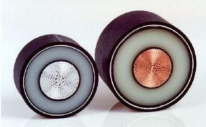
Figure 1 – Extruded XLPE cables with aluminium and copper conductors
What these factors mean is that while an aluminium conductor must be bigger to carry the same current as copper, the aluminium cable can be more cost-effective to purchase and easier to handle.
There are a few variations such as enamelled copper wires (CUE) or oxidized aluminium wires.
Experience in the French grid
As a concrete example, Figure 2 illustrates cable ratings calculated according to the IEC 60287 standard for different types and sizes of conductor. This is based on a typical French installation in a semi-urban area, with the cables laid in PVC ducts embedded in concrete with a trefoil geometry.
It is interesting to note the relative performance of the conductors. In one example, a 2500sqmm Al cable has very close to the same rating as a 2000sqmm Cu cable.
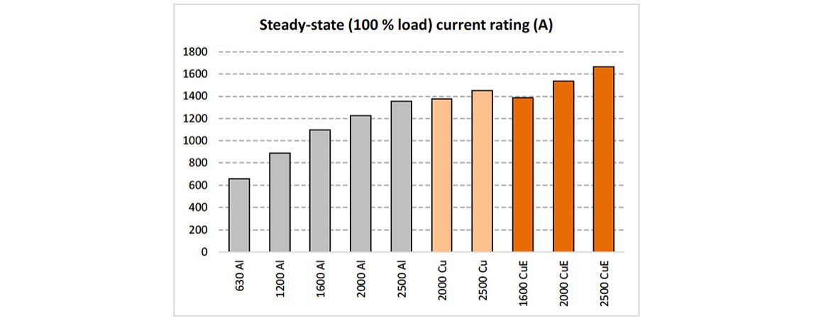
Figure 2 – Current ratings of conductors installed in France. The figures on the x-axis indicate the conductor cross-section eg 2000sqmm
Losses caused by conductors
Losses in the conductor account for the major proportion of the energy lost in an underground cable. Figure 3 shows the typical total losses for cables installed in France as a function of their current rating. The curves end at the steady-state permissible current rating, associated with the maximum temperature of the insulation material (90°C for XLPE = cross-linked polyethylene). The order of magnitude is 30 W/m per cable.
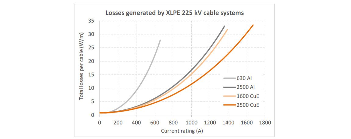
Figure 3 – Total losses dissipated per cable type and size (W/m)
Réseau de Transport d’Electricité (RTE), the French transmission system operator (TSO) has produced statistics showing that underground cable systems operate more than 95% of the time at a current rating lower than 60% of their maximum rating. This means that the losses are normally well under their maximum value. The remaining 5% of the operating time matches with the peak values and most constraining conditions, such as in a severe winter period with extensive use of electrical heating.
The conclusion is that an underground cable is therefore operated generally in conditions leading to “acceptable” losses. This point is essential, considering that power losses dominate the cable’s environmental impact. The closer to the maximum point the cable is operated, then the greater the environmental footprint and the higher the operational cost.
Economical design of cable conductors
When designing a cable system the aim is to stay within the current rating dictated by thermal behaviour. Effectively, the cable is designed not to exceed the maximum temperature of the insulating layer in any operational mode. Most of the time, the design engineer will select the size of conductor that allows the required operating temperature while staying on the safe side within a wide range of standardized sizes.
Until recently, this approach was regarded as offering the lowest investment cost. However, the global cost of a power link also depends on the actual cost of the energy losses. A bigger conductor, although more expensive on initial purchase, may generate lower losses than the thermally designed conductor. Therefore, it can become significantly more cost-effective after a few decades.
This approach is explored in Figure 4 that looks at the case for a cable system carrying 700 A.
Data is plotted on the graph as a function of the conductor size (two colours are used for Al and Cu conductors) and the investment cost of the installed system. The investment cost is made up of the actual cost of the losses at the specified current rating and the total cost.
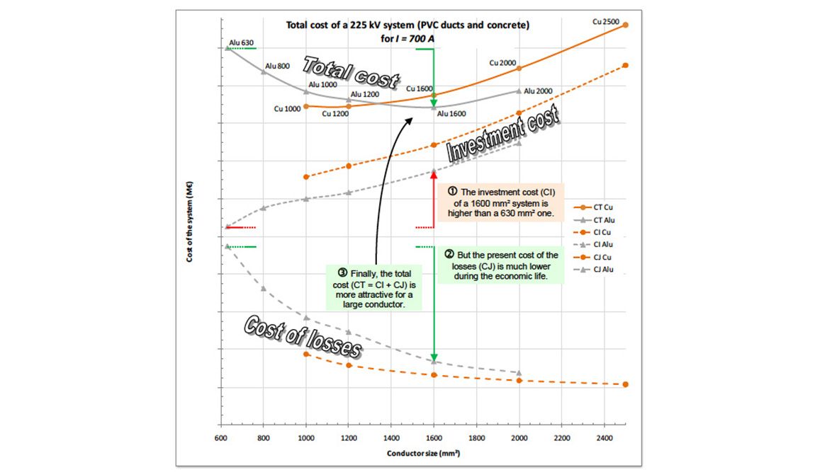
Figure 4 – Investment cost + actual cost of losses = total cost during the economic life of the cable
The investment costs increase with the conductor size, while the cost of losses decreases as there is less electrical resistance. The combination of both trends leads to U-shaped curves with an optimal conductor size. In the example, 1600sqmm Al is the most cost-effective conductor to transmit 700 A over a project life of 50 years. Yet, 630sqmm Al would have been selected from a strict thermal design point of view.
This optimisation is not only of an economic nature. The lower losses also play a favourable role in terms of environmental impact. The benefits can include less risk of thermal aging, reduced risk of thermal runaway due to uncontrolled soil drying, a larger safety margin to handle load peaks or unexpected hot spots, margins for overloads, etc.
Furthermore, lower losses help in limiting global warming.
The prospects for very large aluminium conductors
While maximum standardised cross-sections of conductors have moved from 1600 to 2500sqmm within recent years, some manufacturers are now offering new solutions with aluminium conductors of 3000sqmm or 4000sqmm, pushing the present limits of copper conductors.
Studies have been carried out to assess the interest in these huge components in terms of performance, installation, economics and environmental impact. They show that, for a given current rating, a cable with a very large aluminium conductor generates less energy losses than a cable with a smaller copper conductor of one or two sections.
The lower investment cost of the resulting aluminium cables could bring significant savings, despite the increased cost of installation (excavation, cable laying, assembly of joints, etc.). Design engineers then have to balance the attractive global cost with a number of additional constraints.
These include increased civil works, more rigid conductors and lower strength to resist pulling during installation, increased size of drums or lower delivery length on site, which means shorter sections and more cable joints. A larger conductor diameter also involves accessories of bigger size.
Perhaps the most significant barrier is that there is currently no experience in terms of the qualification of such huge cable systems.
Utilities and manufacturers will need to collaborate to address this challenge. However, at the conductor sizes used today there is substantial practical experience showing clearly that aluminium represents an important alternative to copper.
Thorne & Derrick
Nexans Main UK Stockist & Distributor
Contact us for Competitive Prices & Fast Delivery from Stocks for Heat Shrink, Cold Shrink & EPDM Rubber Connectors, Joints & Terminations up to 66kV.
Thorne & Derrick International are specialist distributors of LV, MV & HV Cable Accessories, Jointing, Substation & Electrical Equipment – servicing UK and global businesses involved in cable installations, jointing, substation, overhead line and electrical construction at LV, 11kV, 33kV, 66kV and EHV.
Stocking & Supplying | Duct Seals | Cable Cleats | Cable Glands | Electrical Safety | Arc Flash Protection | Jointing Tools | Cable Pulling Eqpt | Earthing & Lightning Protection | Feeder Pillars | Cable Joints LV | Joints & Terminations MV HV


Euromold MV HV | Cable Terminations, Connectors, Elbows & Joints
WITHDRAWN IEC 61914:2009 | Cable Cleats for Electrical Installations
August 4th, 2021
By Chris Dodds | Sales & Marketing Manager at Thorne & Derrick International | Specialist Distributor for Ellis Patents | UK Leading Manufacturer of Cable Cleats for LV MV HV Power System Protection

The following article has been authored with the intent to highlight a serious specification shortcoming with respect to the understanding of conformance to the current IEC standard and the short-circuit testing and purchasing of cable cleats.
Working with Ellis Patents, Thorne & Derrick have successfully addressed this issue across several recent UK projects in the offshore wind, battery storage, utility substation and data centre sectors – needless to say, power is everywhere, and we hope this article will lead to a more widespread correction and update at specifier and contractor levels throughout the electrical industry.
Thorne & Derrick are a leading Specialist Distributor of LV HV Jointing, Earthing, Substation & Electrical Eqpt; this includes Cable Management, Fastening & Support Systems such as cable ties, cable hangers and strapping systems for LV up to 132kV power cable networks located onshore and offshore in industrial, hazardous and high voltage applications.
To nutshell this for us, you should ensure your cable cleats are tested to IEC61914:2015 – IEC61914:2009 is Revised, Superseded and Withdrawn. Here is why.
So What’s Changed?
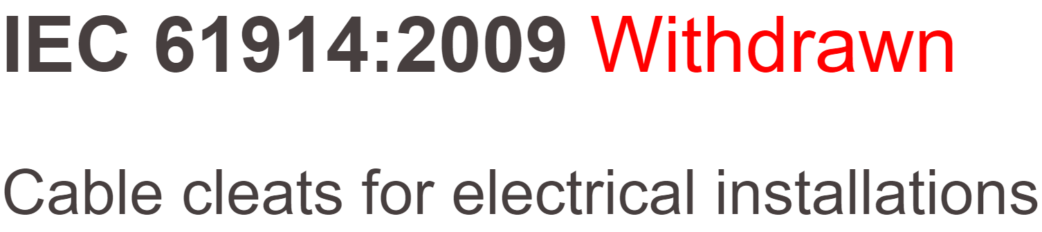
IEC 61914:2009 Is Withdrawn
IEC 61914:2015 is available as IEC 61914:2015 RLV which contains the International Standard and its Redline Version, showing all changes of the technical content compared to the previous edition.
IEC 61914:2015 specifies requirements and tests for cable cleats and intermediate restraints used for securing cable in electrical installations. Cable cleats provide resistance to electromechanical forces where declared. This standard includes cable cleats that rely on a mounting surface specified by the manufacturer for axial and/or lateral retention of cables.
This 2nd Edition of IEC61914 cancels and replaces the first edition published in 2009. This edition constitutes a technical revision. This edition includes the following significant technical changes with respect to the previous edition:
a) Additional declaration and test for lateral load retention depending on cleat mounting orientation with associated new figures;
b) Additional declaration of the distance between the cable centres in any short-circuit test and associated new figures;
c) Specification of the cable to be used in short-circuit testing and relaxation of the ambient temperature limits for the test;
d) Additional requirement to photograph the short-circuit test arrangement before and after the test and to record more complete details of the cable used;
e) Revised parameters for the test of resistance to UV light.
This edition also includes the following editorial changes with respect to the previous edition:
f) Revised and updated normative references and bibliography;
g) Editorial clarification of definitions;
h) Editorial clarification of procedures for selection of test samples and the testing of cleats designed for more than one cable;
i) Relaxation of some mandrel material requirements;
j) Clarification of the inspection requirements following a short-circuit test and adding the option of either a.c. or d.c. voltage testing following a second short-circuit;
k) Clarification that the resistance to corrosion test applies to all types of fixing;
l) New cleat example illustration;
m) Limitations of use of the formulae in Annex B added.
“Cable cleats are critical electrical safety products – in the event of a short circuit they can protect your people, not just plant. During a recent tender bid we were alerted to non-conformance of a competitor product during the technical qualification procedure for a major UK infrastructure project. Simply, their product was tested to the cancelled 2009, not superseding 2015 version. Thorne & Derrick distribute LV HV Cable Accessories & Electrical Equipment from market-leading manufacturers tested to the current range of international standards,” comments Chris Dodds (Sales Manager at Thorne & Derrick).
“The closest example I can think of for this is car seat belts. If you were on the market to purchase a car and were advised that the seatbelts on the car you had chosen were not compliant to the latest industry standards, you may decide against purchasing that car due to safety concerns. Moreover the car would not be safe for sale in UK or European markets and would not bear the required UK CA or CE mark. Cable cleats for cables can be viewed in a similar way to seatbelts in cars as they both perform safety functions, adds Noman Shabir (National Sales Manager at Ellis Patents).
All cable cleats stocked and supplied by Thorne & Derrick are short-circuit tested to the current updated version IEC61914:2015.


