

Earthing
Earth Mats, Earth Tape & Portable Earthing
July 23rd, 2026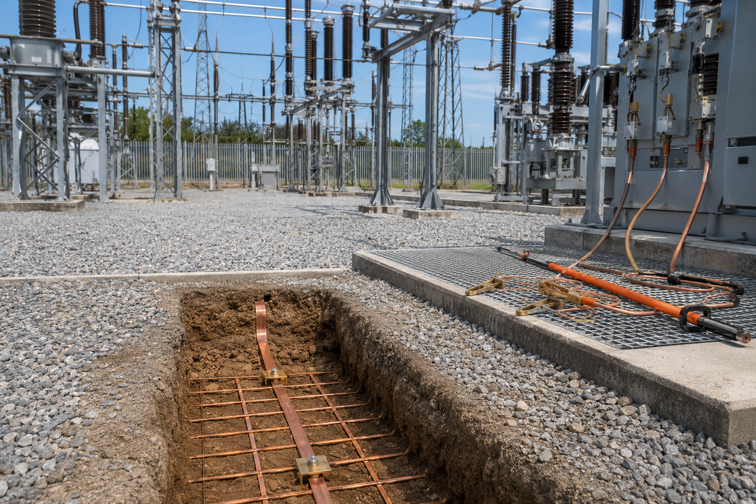
Earth mats, earth tape and portable earthing devices all form part of electrical earthing and safety systems, but they are not the same thing. Some are permanent components buried or fixed into an earthing system, while others are temporary safety devices used during maintenance, isolation and work on electrical equipment.
In LV, MV and HV electrical networks, earthing is essential for safety, fault current control, equipment bonding, lightning protection and reliable operation of electrical infrastructure. Correctly specified earthing systems help manage fault currents, reduce dangerous touch and step voltages, bond metallic structures and provide a route for electrical energy to return safely to earth.
Earth mats and copper earth tape are normally used as part of a fixed earthing system. Portable earthing kits are temporary short-circuiting and earthing devices used by authorised personnel after isolation to help make electrical equipment safe to work on.
Thorne & Derrick supply earth tapes, rods, bars and copper earthing products, copper earth mats, copper earth tape and portable earthing kits for LV, MV and HV electrical networks, substations, overhead lines, power cables and industrial power systems.
Quick Answer: Earth Mats, Earth Tape & Portable Earthing
Earth mats are copper earthing electrodes used to help reduce step and touch voltage risks, especially around substations, switchrooms and high voltage equipment. Copper earth tape is a flat copper conductor used to connect earthing electrodes, earth bars, structures and electrical equipment. Portable earthing devices are temporary short-circuiting and earthing kits used after isolation to help protect authorised workers during maintenance.
The key difference is that earth mats and earth tape are normally part of a fixed, permanent earthing system. Portable earthing kits are temporary safety equipment applied, tested and removed by trained personnel as part of safe working procedures.
What Is Electrical Earthing?
Electrical earthing is the process of connecting electrical equipment, structures, cable systems or lightning protection systems to earth using conductors, electrodes and bonding connections. The purpose is to provide a controlled path for fault current, lightning current or unwanted electrical energy.
Earthing systems help:
- Protect people by reducing dangerous touch and step voltage risks.
- Protect equipment by providing a return path for fault current.
- Support protective devices by helping fault current flow so protection can operate.
- Bond metallic structures to reduce voltage differences between exposed conductive parts.
- Support lightning protection systems by providing a route for lightning current to dissipate into earth.
- Improve network safety in substations, industrial facilities and power distribution systems.
In practical terms, earthing systems are made up of components such as copper earth tape, earth rods, earth mats, earth plates, earth bars, clamps, conductors, inspection pits, Marconite and Bentonite.
What Are Earth Mats?
An earth mat is an earthing electrode, often manufactured from copper tape in a lattice or solid arrangement, used to improve earthing performance and help control touch and step voltage risks.
Earth mats are commonly used around:
- Substation switchgear
- Transformer areas
- High voltage switching points
- Outdoor electrical structures
- Street works and compact earthing installations
- Lightning protection electrodes
- Areas where potential grading is required
Power & Cables explains that earth mats manufactured from high conductivity copper tape help reduce the danger of exposure to high step and touch voltages for substation and authorised personnel working on high voltage switching.
View copper earth mats for substation, utility and electrical infrastructure applications.
What Is Copper Earth Tape?
Copper earth tape is a flat copper conductor used to connect earthing electrodes, electrical equipment, structural steelwork, earth bars and lightning protection systems.
It is widely used because copper provides high conductivity and can be installed in trenches, along structures, around substations and as part of buried earth grids. Earth tape can be supplied in different widths and thicknesses depending on the required current carrying capacity, mechanical strength and project specification.
Typical uses of copper earth tape include:
- Buried earth grids
- Substation earthing systems
- Lightning protection down conductor connections
- Equipment bonding
- Transformer and switchgear earthing
- Earth rod interconnections
- Connections to earth bars and test links
Power & Cables supplies bare and covered copper earth tapes for LV, MV and HV substations, buildings and electrical infrastructure. :contentReference[oaicite:3]{index=3} Wallis copper earth tapes are also listed for earthing and lightning protection applications.
What Are Portable Earthing Devices?
Portable earthing devices are temporary earthing and short-circuiting kits used by authorised electrical workers after equipment has been isolated, tested and confirmed safe for the application of earths.
They are used to help protect workers against:
- Accidental re-energisation
- Induced voltages
- Stored electrical energy
- Unexpected backfeed
- Fault current during maintenance conditions
Portable earthing kits typically include clamps, insulated earth leads, short-circuiting leads, operating sticks and connection accessories. CATU portable earthing and short-circuiting kits are available with choices of earth clamps for live end and earth end applications, jumper clamps for LV switchboards and overhead line clamps.
Power & Cables also lists portable earthing leads in kit form for substations, including field earths, trailing earths, bridging earths, circuit main earths, drain earths and NSI24 kits.
Fixed Earthing vs Portable Earthing
Fixed earthing and portable earthing are often confused, but they have different purposes.
Both are important. A fixed earthing system does not remove the need for portable earthing procedures, and portable earthing equipment does not replace a properly designed permanent earth grid.
Substation Earthing Applications
Substations require carefully designed earthing systems because fault current levels can be high and personnel may need to operate or maintain equipment close to metallic structures, switchgear, transformers and cable systems.
Earthing products used in substations may include:
- Copper earth tape for buried earth grids and bonding.
- Copper earth mats for potential grading and localised step/touch voltage control.
- Earth rods to improve connection to the general mass of earth.
- Earth bars for common earth termination points.
- Earth clamps and connectors for conductor connections.
- Marconite or Bentonite where ground conditions require earthing enhancement.
- Portable earthing kits for safe maintenance procedures.
Copper lattice earth mats are used in high fault current and step potential avoidance applications such as high voltage substations and switchrooms.
For wider earthing products, see earth tapes, rods, bars and copper earthing accessories.
Earth Rods, Earth Bars & Accessories
Earth mats and earth tape are normally used alongside other earthing products. A complete earthing system may include several different components.
Power & Cables states that earth rods are used to provide the interface to ground in all soil conditions for overhead and underground electricity distribution and transmission networks, including low, medium and high voltage substations, towers and power distribution applications.
Earth bars are used for terminating cable lugs or earth tape connections and are commonly manufactured from high-conductivity copper bar.
Marconite, Bentonite & Soil Conditions
The performance of an earthing system depends heavily on the surrounding ground conditions. Dry, rocky, sandy or high-resistivity soil may make it harder to achieve the required earth resistance using rods and tape alone.
Earthing enhancement materials can help improve electrode contact with the surrounding soil.
- Marconite is a conductive aggregate used with cement and water to form conductive concrete around earth electrodes.
- Bentonite is a clay-based earthing compound used as backfill around electrodes.
Marconite and Bentonite should not be treated as the same product. The correct selection depends on the earthing design, soil resistivity, resistance target, installation method and long-term performance requirements.
For more detail, see the Power & Cables guide to Marconite earthing.
How To Select Earthing Products
Earthing products should be selected as part of a complete electrical earthing design. The right products depend on the system voltage, fault level, soil conditions, resistance target, location, network type and maintenance requirements.
For portable earthing kits, selection should also consider the equipment type, voltage level, clamp type, connection points, short-circuit rating, lead length and approved safe working procedure.
Common Earthing Mistakes
Earthing errors can create serious safety risks, especially around substations, overhead lines, switchgear and high fault current electrical systems.
Common mistakes include:
- Confusing fixed earthing with portable earthing – permanent electrodes and temporary safety earths have different purposes.
- Ignoring soil resistivity – earthing design should be based on site conditions, not assumptions.
- Using undersized conductors – copper tape and conductors must be suitable for the required fault current and duration.
- Forgetting step and touch voltage – low earth resistance alone does not always guarantee personnel safety.
- Poor connection quality – loose, corroded or unsuitable connections can reduce earthing performance.
- Failing to test the system – earth resistance and continuity testing are essential after installation.
- Selecting portable earths without fault rating – portable earthing kits must be selected for the fault level and application.
- Using the wrong clamp type – clamp design must suit the connection point, such as busbar, conductor, earth tape or switchgear point.
- Not maintaining portable earthing equipment – leads, clamps and sticks should be inspected and maintained according to site procedures.
Earthing should always be designed, installed, tested and maintained by competent personnel.
Related Earthing & Electrical Safety Products
Earthing products are usually specified as part of a complete earthing, bonding and electrical safety system.
- Earth Tapes, Rods, Bars & Copper Earthing Products – full range of fixed earthing products for LV, MV and HV systems.
- Copper Earth Mats – earth mats for substation, switchroom and potential grading applications.
- Copper Earth Tape – bare and covered copper tape for earthing and lightning protection.
- Earth Rods – electrodes for overhead and underground power networks.
- Earth Bars – copper bars for earthing terminations and bonding connections.
- Portable Earthing Kits – temporary earthing and short-circuiting kits for substations, overhead lines and cable systems.
- Marconite – conductive concrete aggregate for low resistance earthing systems.
- Bentonite – earthing compound for electrode backfill applications.
- AN Wallis Earthing & Lightning Protection – copper earth rods, tapes, bars, mats, clamps and lightning protection products.
Earthing FAQs
Q: What is an earth mat?
A: An earth mat is a copper earthing electrode, often made in a lattice or solid arrangement, used to improve earthing performance and help reduce step and touch voltage risks around electrical equipment.
Q: What is copper earth tape used for?
A: Copper earth tape is used to connect earthing electrodes, earth bars, structural steelwork, electrical equipment and lightning protection systems. It is commonly used in buried earth grids and substation earthing systems.
Q: What is a portable earthing device?
A: A portable earthing device is temporary electrical safety equipment used to earth and short-circuit isolated electrical equipment during maintenance. It usually includes clamps, insulated leads and connection accessories.
Q: What is the difference between fixed earthing and portable earthing?
A: Fixed earthing is the permanent earthing system installed as part of the electrical infrastructure. Portable earthing is temporary safety equipment applied by authorised personnel during isolation and maintenance work.
Q: Where are earth mats used?
A: Earth mats are commonly used around substations, switchrooms, transformer areas, high voltage switching points, outdoor electrical structures and locations where potential grading is required.
Q: Are earth mats and earth rods the same?
A: No. An earth rod is a vertical or angled electrode driven or installed into the ground. An earth mat is a wider copper electrode arrangement, often lattice-based, used for potential grading and earthing performance.
Q: When is portable earthing used?
A: Portable earthing is used during electrical maintenance and isolation procedures after equipment has been isolated and proved safe for the application of earths. It should only be used by authorised and trained personnel.
Q: What products are used in an earthing system?
A: Earthing systems can include copper earth tape, earth rods, earth mats, earth bars, clamps, connectors, inspection pits, Marconite, Bentonite and portable earthing equipment depending on the application.
Conclusion
Earth mats, earth tape and portable earthing devices are all important parts of electrical earthing and safety, but each product has a different role.
Earth mats and copper earth tape are used as part of permanent earthing systems for substations, buildings, lightning protection, power networks and electrical infrastructure. Portable earthing kits are temporary safety devices used by authorised personnel during maintenance, isolation and work on electrical systems.
Correct selection depends on the application, voltage level, fault current, soil conditions, step and touch voltage requirements, connection points, testing requirements and safe working procedure.
Thorne & Derrick supply earth mats, copper earth tape, earth rods, earth bars, Marconite, Bentonite and portable earthing kits for LV, MV and HV electrical networks, substations, overhead lines, underground cables, lightning protection and industrial power systems.
Marconite Earthing Explained
July 2nd, 2026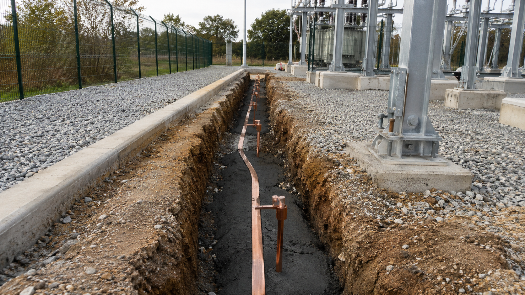
Marconite earthing is used to help create low resistance, stable and long-lasting earthing systems by surrounding earth electrodes with an electrically conductive concrete. Marconite is a conductive aggregate that is mixed with cement and water to form a conductive concrete around earth rods, copper earth tapes, earth mats or other earthing electrodes.
In simple terms, Marconite improves the contact between the earth electrode and the surrounding ground. This helps reduce earth resistance, especially where soil conditions are difficult, dry, rocky, sandy or naturally high in resistivity.
Marconite is commonly used for substation earthing, lightning protection systems, telecoms sites, rail infrastructure, power networks, industrial plants, renewable energy projects, data centres and critical electrical installations where a reliable earthing system is essential.
Thorne & Derrick supply Marconite earthing compound, together with earth tapes, rods, bars and accessories, earth mats and Bentonite earthing compound for LV, MV and HV electrical earthing applications.
Quick Answer: What Is Marconite Earthing?
Marconite earthing is the use of Marconite conductive aggregate around earth electrodes to help create a low resistance earthing system. Marconite is mixed with cement and water to form a conductive concrete that surrounds earth rods, copper earth tape, earth mats or other electrodes.
The conductive concrete increases the effective contact area between the electrode and the surrounding ground. This can help improve earthing performance, especially where normal soil conditions make it difficult to achieve the required earth resistance.
What Is Marconite?
Marconite is an electrically conductive aggregate material used in earthing systems. When mixed with cement and water, it forms a conductive concrete that can be placed around earth electrodes to improve the electrical connection between the electrode and the soil.
Instead of acting like ordinary concrete, Marconite concrete is designed to conduct electricity. This makes it useful where engineers need to improve the performance of an earthing system but the natural ground conditions are not suitable enough on their own.
Marconite is commonly described as a conductive concrete or conductive backfill material. It is used to enhance the performance of earth electrodes such as:
- Copper earth rods
- Copper earth tape
- Copper lattice earth mats
- Earth plates
- Lightning protection electrodes
- Substation earthing systems
Because it forms a solid conductive mass after curing, Marconite can provide a stable earthing enhancement where a permanent low resistance solution is required.
How Does Marconite Earthing Work?
An earthing system works by creating a reliable electrical connection between the electrical installation and the general mass of earth. The lower and more stable the earth resistance, the more effective the earthing system can be in helping fault current, lightning current or unwanted electrical energy dissipate safely.
Marconite earthing works by increasing the effective surface area and conductivity around the buried electrode. Instead of the electrode relying only on direct contact with natural soil, the electrode is surrounded by conductive concrete.
The final resistance of an earthing system depends on many factors, including soil resistivity, electrode design, electrode spacing, installation depth, moisture conditions, fault current requirements and the overall earthing design.
Where Is Marconite Used?
Marconite is used wherever a reliable low resistance earthing system is required and normal soil conditions may not provide the desired performance.
Typical applications include:
- Electrical substations – LV, MV and HV earthing systems for power distribution and transmission networks.
- Lightning protection systems – earthing electrodes for lightning current dissipation.
- Telecommunications sites – tower, mast and equipment earthing where stable resistance is required.
- Rail infrastructure – earthing for signalling, telecoms, substations and electrical infrastructure.
- Renewable energy projects – solar farms, wind farms, battery storage and grid connection earthing.
- Industrial plants – process facilities, factories, data centres, utilities and critical power installations.
- High resistivity soil locations – dry, rocky, sandy or poor conductivity ground conditions.
Marconite is often used where the earthing design must meet a target resistance value but the site conditions make that difficult using basic earth rods alone.
Benefits Of Marconite Earthing
The main benefit of Marconite earthing is that it helps improve the electrical performance of the earthing system.
Power & Cables lists Marconite as a granulated electrically conductive aggregate that replaces sand in cement mixes to create electrically conductive concrete.
Marconite vs Bentonite
Marconite and Bentonite are both used in earthing applications, but they work in different ways and are not the same material.
Bentonite is a moisture-retaining clay-based material often used as an earthing backfill around electrodes. Marconite is a conductive aggregate mixed with cement to form conductive concrete.
For many projects, the selection between Marconite and Bentonite should be made by the electrical designer or earthing specialist based on soil resistivity testing and the required earthing performance.
View Bentonite earthing compound and Marconite earthing compound.
Marconite With Earth Rods, Mats & Copper Earth Tape
Marconite is rarely considered on its own. It is usually part of a complete earthing system that includes electrodes and conductors.
Common earthing components used with Marconite include:
- Earth rods – driven or installed into the ground to provide an earth electrode.
- Copper lattice earth mats – used for potential grading and earthing, especially where touch and step potential must be considered.
- Copper earth tape – used to interconnect electrodes, earth bars, equipment and buried earthing systems.
- Earth bars – used for terminating earth conductors and bonding connections.
- Earth plates – used where a plate electrode design is required.
Marconite helps improve the interface between these electrodes and the surrounding soil. For example, an earth rod may be installed in a drilled hole with Marconite conductive concrete surrounding it, or copper tape may be laid in a trench with Marconite used as an engineered conductive backfill.
The final arrangement should always be designed around the required earth resistance, fault current capacity, step and touch voltage limits, installation environment and applicable standards.
Marconite For Substation Earthing
Substations require reliable earthing systems because fault current, lightning current and transferred potentials must be controlled safely. Earthing is also important for equipment bonding, personnel safety, switchgear operation, transformer installations and protection systems.
Marconite can be used in substation earthing designs where a stable low resistance system is required, particularly if the natural ground conditions are challenging.
Typical substation earthing uses include:
- Earth rod installations around substation compounds.
- Copper earth tape trenches around switchgear, transformers and structures.
- Copper lattice earth mats for potential grading applications.
- Transformer and switchgear bonding to the main earth grid.
- Lightning protection earthing for masts, structures and exposed equipment.
- Renewable energy grid connection substations where stable earthing is required.
Substation earthing should be designed by competent electrical engineers using soil resistivity data, fault level information, site layout and the required safety performance.
How Is Marconite Installed?
Marconite is normally mixed with cement and water to form conductive concrete. The mixture is then placed around the electrode system before it cures.
A typical Marconite installation may involve:
- Excavating a trench or borehole for the earth electrode.
- Installing the earth electrode, such as a rod, tape, mat or plate.
- Mixing Marconite with cement and water according to the project or manufacturer guidance.
- Placing the conductive concrete around the electrode to ensure good contact.
- Allowing the material to cure before final testing and backfilling where required.
- Testing the completed earthing system to confirm performance.
The exact installation method should be confirmed against the manufacturer’s guidance and the earthing design. Poor mixing, poor compaction, poor electrode contact or incorrect placement can reduce the effectiveness of the installation.
How To Select Earthing Materials
Selecting Marconite, Bentonite or another earthing material depends on the complete earthing design. The material is only one part of the system.
Earthing system design should always be based on site conditions, not assumptions. Marconite can be very effective, but only when used correctly as part of a properly designed earthing system.
Common Marconite Earthing Mistakes
Marconite is a specialist earthing material, so poor installation or incorrect specification can reduce performance.
Common mistakes include:
- Using Marconite without a proper earthing design – the material should support the design, not replace it.
- Ignoring soil resistivity – site soil data is essential for designing an effective earthing system.
- Poor contact with the electrode – Marconite must surround the electrode properly to be effective.
- Incorrect mixing – the material should be mixed and placed according to manufacturer or project guidance.
- Confusing Marconite and Bentonite – they are both used for earthing, but they are different materials with different installation behaviour.
- Failing to test after installation – earth resistance should be measured to confirm that the design target has been achieved.
- Forgetting step and touch voltage considerations – low resistance alone is not the only safety factor in complex earthing systems.
- Treating every site the same – rocky, dry, sandy or wet ground conditions may require different earthing arrangements.
For critical installations, the earthing design should be reviewed by a competent electrical engineer or earthing specialist.
Related Earthing Products
Marconite is usually specified alongside other earthing and lightning protection products.
- Marconite Earthing Compound – conductive aggregate for low resistance earthing systems.
- Bentonite Earthing Compound – earthing backfill compound for earth electrodes and trenches.
- Copper Earth Tape – copper tape for buried earth grids, bonding and lightning protection systems.
- Earth Rods – earth electrodes for low resistance earthing systems.
- Copper Earth Mats – copper lattice mats for potential grading and earthing applications.
- Earth Bars – copper earth bars for bonding and termination of earthing conductors.
- Wallis Earthing & Lightning Protection – earthing, bonding and lightning protection accessories.
Marconite Earthing FAQs
Q: What is Marconite?
A: Marconite is an electrically conductive aggregate used in earthing systems. It is mixed with cement and water to form conductive concrete around earth electrodes.
Q: What is Marconite earthing?
A: Marconite earthing is the use of Marconite conductive concrete around earth rods, copper tape, earth mats or other electrodes to help reduce earth resistance and improve earthing performance.
Q: Is Marconite the same as Bentonite?
A: No. Marconite is a conductive aggregate mixed with cement to form conductive concrete. Bentonite is a clay-based earthing backfill compound. Both can be used in earthing systems, but they are different materials.
Q: What is Marconite used for?
A: Marconite is used to improve earthing systems in substations, lightning protection, telecoms, rail, utilities, renewable energy, industrial sites and high-resistivity ground conditions.
Q: How does Marconite reduce earth resistance?
A: Marconite reduces earth resistance by forming a conductive concrete around the electrode. This increases the effective contact area and improves the conductive path between the electrode and surrounding soil.
Q: Can Marconite be used with earth rods?
A: Yes. Marconite is commonly used around earth rods to improve the contact between the rod and surrounding ground. It can also be used with copper earth tape, earth mats and other electrodes.
Q: Is Marconite suitable for substations?
A: Yes. Marconite can be used in substation earthing systems where a stable low resistance earth is required, particularly in difficult ground conditions. The system should be designed by a competent engineer.
Q: Does Marconite need to be tested after installation?
A: Yes. The completed earthing system should be tested after installation to confirm that it meets the required resistance and safety performance set out in the earthing design.
Conclusion
Marconite earthing is used to create low resistance, stable and long-lasting earthing systems by forming conductive concrete around earth electrodes. It is especially useful where normal soil conditions make it difficult to achieve the required earth resistance using earth rods or copper electrodes alone.
Marconite can be used with earth rods, copper earth tape, copper lattice earth mats, earth plates and lightning protection systems. It is commonly specified for substations, rail, telecoms, utilities, renewable energy projects, data centres and industrial power infrastructure.
Correct design and installation are essential. Marconite should be selected based on soil resistivity, resistance targets, fault current requirements, electrode layout, site conditions and the overall earthing design.
Thorne & Derrick supply Marconite earthing compound, Bentonite, copper earth tape, earth rods, earth bars, copper lattice earth mats and earthing accessories for LV, MV and HV electrical infrastructure projects.
Earthing Armoured Cables To Safely Protect LV AC Cables In The Solar Industry
February 28th, 2024Challenge | This week a Solar EPC client of Thorne & Derrick engaged our Technical Sales Department to assist with ongoing O&M issues relating to the termination connection of steel wire armour (SWA) on 450off 4 core x 240sqmm LV AC cables, 0.6/1kV – the outdoor location cables are connected to a string inverter and the MV station at the remote end on a UK based 50MW solar farm in Derbyshire. The cable armouring provides mechanical protection but is not intended to circulate electrical current.
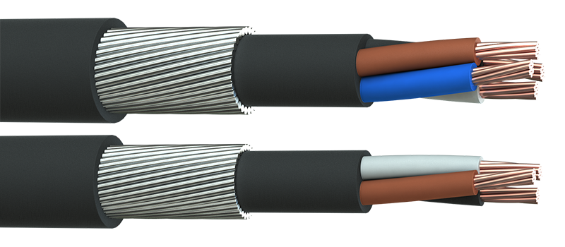
SWA Cable Steel Wire Armoured Cables | Image FS Cables
BS7671 Clause 522.8.10
“Except where installed in a conduit or duct which provides equivalent protection against mechanical damage, a cable buried in the ground shall incorporate an earthed armour or metal sheath or both, suitable for use as a protective conductor. The location of buried cables shall be marked by cable covers or a suitable marker tape. Buried conduits and ducts shall be suitably identified. Buried cables, conduits and ducts shall be at a sufficient depth to avoid being damaged by any reasonably foreseeable disturbance of the ground.”
Earthing Armoured Cables
Solution
Initially, from the viewpoint of the above British Standard the client considered connecting the wire armour at the MV station to ensure that during a fault (e.g.cable strike) an earth path exists to allow safe disconnection of the cable. Earthing the armours of buried SWA cables is important for safety – this prevents/reduces the severity of electric shocks and equipment damage should a person dig inadvertently into the cable. The cable wire armours provide a complete earth path around the cable. Utilizing a single phase within a 4 core cable as earth is not sufficient as it does not offer complete protection around the circumference of the cable. Also, in solar farm installations un-earthed wire armours can have induced voltage from excessive current generated. Therefore, the contractor should always consult the circuit designer.
Customer Service
From initial application, to concept, to design and to sample acceptance by the end client we subsequently completed the despatch and delivery of their order in 5 working days for 450off Armour Earthing Kits.
Important Note
Solderless earth kits that are intended for copper tape screens (MV cables) are a substandard method to earth SWA cables. Solderless earth kits utilize a constant force spring which do not offer a secure earth bond for SWA’s. Also, the cross sectional area of the braid within these kits is inadequate which is why you should always use an armour earth kit for this application. Contact us to discuss your application.

Innovative Connection & Grounding Solutions for LV Cables
Excerpt from Installation Instruction
Heat Shrink Outdoor Armour Earth Kit To Suit
XLPE SWA PVC
The Heat Shrink Outdoor Armour Earth Kit includes medium wall adhesive lined heat shrink tubes, mastic tapes, solder-blocked earth braids and clamps. Contact us for further information, technical support or for a quotation.

THORNE & DERRICK are Specialist Distributors of LV HV Solar Cable Accessories, Jointing, Termination, Earthing & Electrical Equipment 1500V DC to 33kV – we service UK and global businesses involved in cable installations, jointing, substation and electrical construction.
Since 1985, T&D have established reputation based on SERVICE | INTEGRITY | TRUST – we are highly customer responsive and absolutely committed to providing a world-class service.
We provide expert technical support and supply from a multi-million pound stock holding:
- Cable Joints, Terminations & Connectors
- Earthing & Lightning Protection
- Cable Accessories – Lugs & Glands
- Circuit Protection & Fuses
- Cable Cleats & Clamps
- Electrical Safety Equipment
- Cable Pulling & Laying Equipment
- Arc Flash Protection & Clothing
- Cable Duct Seals & Transit Systems
- Surge Arresters & Bushings
- MV HV Overhead Line & Substation Power Products
>> MORE INFO <<

Further Reading

Thorne & Derrick are Specialist Distributors of Innovation Tooling & Accessories for LV HV Power Systems to facilitate safe and reliable cutting, crimping, preparation, termination and installation of cables, 600V to 132kV.
Power Systems Earthing | An Introduction to Substation and Electrical Equipment Protection
October 31st, 2023
Power Systems Earthing | Electrode System
Power Earthing Systems
An earth electrode system, professionally designed by competent engineers, is essential to ensure the safety of personnel and protection of equipment from dangerous voltages in and around medium and high voltage (MV & HV) substations.
Earth Electrode Systems are a critical part of any electrical system and they are often seen as inert which may sometimes be dismissed as cost-saving or forgotten about until a later stage of the project – should these systems fail due to incompetent design or the use of cheap substandard components, the resulting events may be catastrophic or even lethal.
For instance this will carried out by competent and highly experienced electrical engineers and technicians. A.N Wallis are able to offer earth electrode system designs and associated testing services using the most up to date Earthing & Lightning Protection Equipment and design software CDEGS.
CDEGS (Copper Earth Electrode Design) is now recognised as the industry standard earthing design analysis software in the UK and in many other parts of the world.
Power Earthing System products, manufactured by A.N Wallis and distributed by Thorne and Derrick from high conductivity copper to BS EN 13601 is installed to protect buildings, overhead lines and medium/high voltage substations (MV-HV) against potentially catastrophic damage that can be caused by a lightning strike resulting in short circuiting.
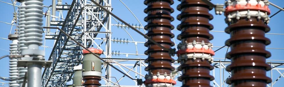
Power Earthing System | A.N Wallis
CDEGS
CDEGS (Current Distribution, Electromagnetic Fields, Grounding and Soil Structure Analysis) is a grounding (earthing) and electromagnetic analysis software package. It is dedicated to accurately analyse problems involving grounding, electromagnetic fields, electromagnetic interference including AC/DC .
This software allows to stress test designs and systems to evaluate performance under given conditions making the electrode systems safe.
using Substation Electrode Systems
A.N Wallis offer high specification test equipment to carry out soil resistivity testing. This helps it gain data from tried and tested methods. It is then analysed using CDEGS software to then produce a representative electrical equivalent soil resistivity model which can be used in the earthing design process.
As a result if this were to fail due to a incompetent design they would be running multiple tests to keep the workplace safe.
The Importance of Earth Bars For Power Earthing Systems
Substation earthing bars (LV HV) are used to marshall earth connections, connect copper earth rods or earth cable conductors using crimp lugs for terminations in substations, cable pits, feeder pillars and switchgear.
Earthing bars can be tinned and bases power coated to improve corrosion resistance. Bars are pre-drilled with cable connection holes with optional threads for installation ease. Manufactured from highest conductivity and quality copper to British Standards.
Full range of standard, single and twin link types for LV, MV & HV switchroom/substations. Customised to suit the earthing requirements of your project on short lead times.
Electrode Systems
To outline, the three main areas to analyse with any Earth Electrode system are:
– Touch, Step and Rise of Earth Potentials (RoEP). (These are also known as Earth Potential Rise (EPR or Ground Potential Rise (GPR).
Thorne & Derrick working with A.N Wallis will liaise with the DNO (Distribution Network Operator) or Electricity Supply Company on your behalf to gain all the required ‘Point of Connection’ data for your new electrical connection. Using the Soil Resistivity data, A.N Wallis produce a conceptual earth electrode system layout based on the existing plant layout drawings and analyse the associated voltage contours using either the MALT or MALZ module of the CDEGS software. Graphical plots are produced using the CDEGS software that visually identifies any ‘hot’ spots around the site that may need further design time.
MALT (CDEGS) assumes that the entire earth mat is at the same voltage, which is very dangerous to consider, particularly on more significant sites with low soil resistivity.
MALZ (CDEGS) does allow for voltage drops along conductors but does not account for inductive or capacitive effects between conductors.
These Touch, Step and Rise of Earth Potential levels are assessed, and only when they are within safe limits will A.N Wallis pass this design for construction.
Further calculations will be carried out to determine whether the site may influence other electrical installations under fault conditions and from that we can determine the site ITU (International Telecommunications Union) classification as either HOT or COLD.
Only once we have confidence that the design parameters are met, a full ‘for construction’ style drawing will be produced.
Key Benefits of Power Earthing Systems
- Provides safety for LV MV HV electrical sites
- Provides protection against dangerous voltage in and around substations
- Helps identify and document loss in Power Earthing Systems
Further Reading
- Earth Bars | Wallis Earth Bar Software (WEBS)
- Correct Termination Of A Cable Lug Onto An Earth Bar | AN Wallis Guide
- AN Wallis Earthing & Lightning Protection | ECA Consultant & Specifier Associate

Earth Rods | Earth Tapes | Copper Earth Plates | Copper Earth Mats

THORNE & DERRICK are national distributors of LV, MV & HV Cable Installation, Jointing, Duct Sealing, Earthing & Electrical Equipment – we service UK and global businesses involved in cable installations, substation, overhead line and the installation of medium/high voltage cable joints and terminations at LV, 11kV, 33kV and HV.
Contact us for 3M Electrical, ABB, Alroc, AN Wallis, CATU Electrical, Cembre, Centriforce, CMP, CSD, Elastimold, Ellis Patents, Emtelle, Euromold, Filoform, Lucy Electric & Zodion, Nexans, Pfisterer, Polypipe, Prysmian, Roxtec, Sicame, WT Henley.
See How DEHN Provides Electrical Protection for Wind Turbines
March 29th, 2023
Electrical Protection For Wind Turbines
Electrical Protection for Wind Turbines
Lightning & Surge Protection by DEHN
Ensure smooth operation and protect investments with lightning and surge protection safety equipment from DEHN.
Committed to the protection of workers and material assets, Thorne & Derrick together with DEHN can offer electrical protection specifically for wind turbines with a range of innovative products.
Thorne & Derrick provide an extensive range of electrical safety equipment including insulating gloves, voltage detectors, insulating matting and portable earthing to ensure worker safety when carrying out maintenance on LV-HV switchgear, substations, cables and electrical equipment.

Electrical Safety Products for LV MV HV Cables, Conductors, Substations & Earthing
Secure profit on your investment
The feed-in remuneration for renewables is sinking worldwide and putting the wind branch under increasing pressure. To ensure that investments in new wind turbines pay off in future, too, the top priority is to optimise the availability of the turbines. This prevents loss of revenue due to downtime and high service and repair costs.
Their height makes wind turbines particularly susceptible to destructive lightning events. If insufficient protective measures are taken, the risk of damage and downtime due to lightning is correspondingly high. An integrated lightning protection system is therefore a must.
It consists of external and internal lightning protection, earthing and equipotential bonding.
Take the safe option and entrust the globally recognised specialist DEHN with your lightning and surge protection. Our high-quality and durable products protect turbines on all continents, from the foundations to the rotor blades. Take advantage of our services and make quicker and verifiable progress. We can assist you by, for example, conducting risk analyses, creating bespoke protection concepts and product solutions, or conducting system tests in our accredited test centre.
Developing lightning protection zone concepts with expertise
To secure the availability of wind turbines, the lightning protection zone concept aims to prevent lightning damage to mechanical and electric components. This is achieved by discharging lightning current and controlling surges.
The lightning protection zone concept for wind turbines described in IEC 61400-24 deals with the topic of lightning protection for wind turbines including detailed information on the selection of lightning and surge protection measures 1).
As the basis for creating a protection concept, a wind turbine is subdivided into lightning protection zones. One distinguishes here between external zones (LPZ 0A und 0B) and internal zones (LPZ 1, LPZ 2…n) 2). The external zones of a wind turbine – except the rotor blade – are determined by way of the rolling sphere method. The subdivision of the internal zones very much depends on the construction of the individual wind turbine and should be conducted accordingly.
Having laid down the relevant lighting protection zones, one can then define the necessary protective measures. It is advisable to create a lightning protection concept at the initial planning stage of a wind turbine to avoid later cost-intensive repairs and retrofitting. Long experience in the field of lightning and surge protection and the numerous system tests conducted for the wind industry have given DEHN the know-how to develop effective lightning protection systems for wind turbines. We will assist you in developing a lightning protection concept for your turbine consisting of external lightning protection, internal lightning protection, equipotential bonding and earthing.
1) IEC 61400-24 Lightning Protection of Wind Turbines
2) LPZ: Lightning Protection Zone
Always reliably informed with DEHNdetect
Lightning Current Measuring System Prevents Subsequent Damage
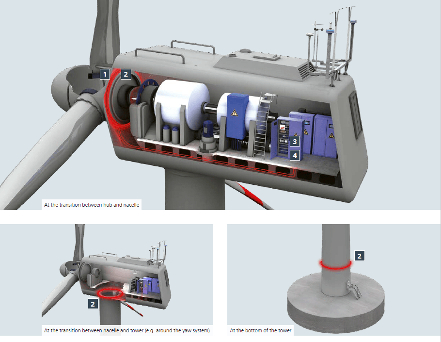
Damage resulting from a lightning strike does not necessarily lead to the immediate failure of the turbine. This means that lightning events often remain undetected, especially in the case of upward flashes where the initial long stroke current flowing is only a few 100 A and can be the main cause of damage, e.g., to the rotor blades.
Continued operation of the turbine can lead to serious subsequent damage. Lightning current measuring systems are often employed to detect lightning events and prevent subsequent damage. However, dangerous upward flashes are not always fully detected due to the low current flow of the measuring system. As well as impulse currents, DEHNdetect also reliably registers these dangerous long stroke currents, thus preventing expensive maintenance work and long downtimes. DEHNdetect identifies the following parameters:
- Impulse current [kA]
- Long stroke current [A]
- Load [C]
- Specific energy [MJ/Ω]
- Rise time [kA/μs]
Benefits:
- Prevention of subsequent damage
- Reduction of maintenance / repair costs
- Reduction of downtime
The system can be integrated in the IT infrastructure of the wind turbine via existing interfaces. The data can then simply be read out and managed using the available SCADA systems. If direct integration is not possible, the data can be transmitted to a cloud and evaluated via a web application. This makes it possible to monitor several turbines or even entire wind parks.
Invest in availability to secure the power supply of your turbine, today and tomorrow.
| DEHNdetect Components | ||
| 1 | 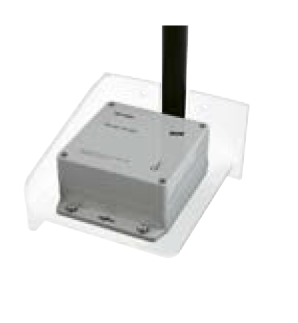 |
DEHNdetect BDU Detector for the wireless detection of lightning current in the rotor. |
| 2 | 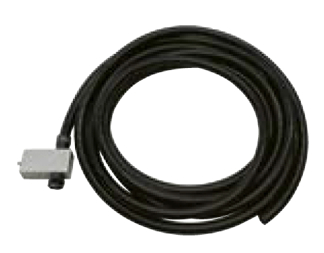 |
DEHNdetect ICC IMP Measuring coil long stroke current and impulse current. Measuring range 60 A to 250 kA. |
| 3 | 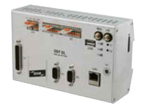 |
DEHNdetect DL Data logger with different interfaces for integration in IT systems. |
| 4 |  |
DEHNdetect integrator Processing of the measuring signals and transmission to the data logger. |
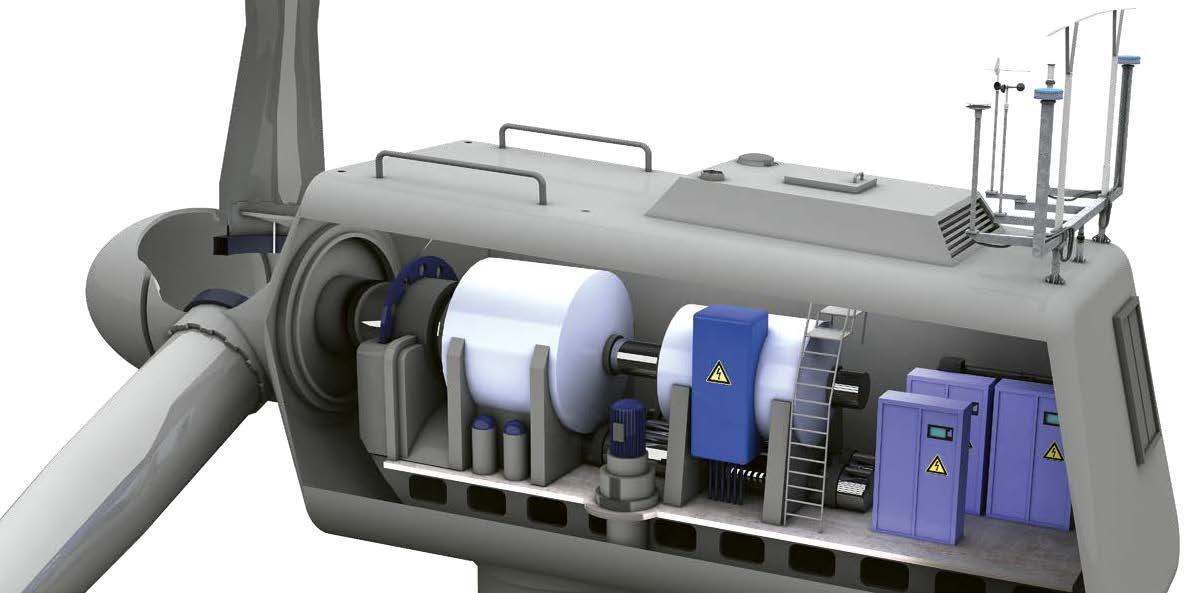
Lightning & surge protection
in the Wind Turbine nacelle
All lightning and surge protective devices by DEHN for application in wind turbines are vibration- and shock-tested in compliance with IEC 60068-2.
Power Supply Systems
By implementing coordinated surge protection measures for power supply systems, the risk of system downtime due to lightning currents and surges can be avoided. This increases the availability of the wind turbine in the long term.
Information Technology Systems
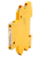
A consistent protection concept prevents damage to information and data systems. Condition monitoring is indispensable for operational safety and plant availablity. The monitoring unit for the condition-oriented monitoring of up to 50 BLITZDUCTORconnect arresters fulfils this task. Remote monitoring is also possible.
| Application | Type | ||
| Power Supply Systems | |||
| 1 | 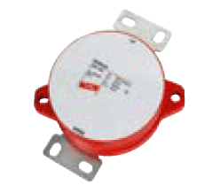 |
DEHNsolid | Rotor blade heating Coordinated type 1 SPD, with 200 kA discharge capacity and low voltage protection level (Up ≤ 2.5 kV). |
| 2 | 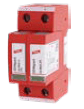 |
DEHNguard M TN CI | Pitch system, aircraft warning light Type 2 SPD, especially space- and cost-saving due to integrated backup fuse. |
| 3 | 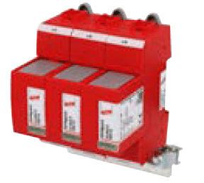 |
DEHNguard SE H 1000 VA FM + earthing clip |
Generator Type 2 SPD, further development of the “Neptune circuit” – Advantages: small dimensions save space and costs, improved protection level. |
| 4 | 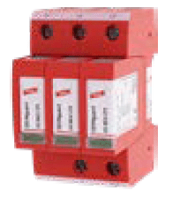 |
DEHNguard M TNC | Voltage supply
Type 2 SPD |
|
Information Technology Systems |
|||
| 5 |
|
BLITZDUCTORconnect |
Protects signal, bus or control lines |
|
|
DEHNpatch Class E |
Universal type 2 SPD for Ethernet and structured cabling up to 250 MHz. |
|
|
|
BLITZDUCTOR VT |
Weather station |
|
|
|
DEHNrecord IRCM |
Condition monitoring unit for up to 50 BLITZDUCTORconnect arresters. With LED status indication and floating remote signalling contact. |
|
Safely discharging lightning current
External Lightning Protection
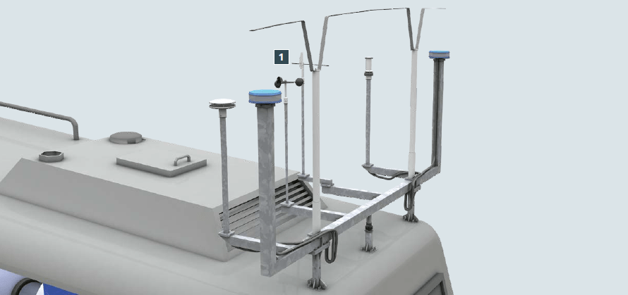
Safe interception and discharge of direct lightning strikes is paramount for the availability of a wind turbine. DEHN ensures that this is the case by testing components like the HVI power Conductor with a lightning current of 200 kA (10/350 μs) as stipulated in IEC 62561. The stainless steel design of the air-termination rods and connection elements fulfils stringent corrosion resistance requirements.
Earthing & Equipotential Bonding
Safe operation of electrical equipment and systems and a well-functioning lightning protection system require an earth-termination system designed according to IEC 61400- 24 1). Connection elements which are capable of carrying short-circuit current ensure the safe contact of the earth-termination system with metal parts of the foundations and the main earthing busbar. A high level of product quality safeguards long-term mechanical strength and corrosion resistance.
| Application | Type | ||
| External Lightning Protection | |||
| 1 | 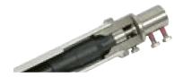 |
HVI power Conductor (in supporting tube with air-termination rod)) |
Class of LPS 1 – 200 kA (10/350 μs) – High-voltage-resistant, insulated down conductor for maintaining the separation distance. |
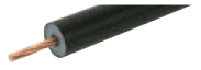 |
HVI power long Conductor (cut to length) |
Individual lengths, on request we can assemble your conductors with the appropriate connection elements. |
|
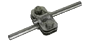 |
UNI disconnection clamp 200 kA | 200 kA lightning current carrying capability according to IEC 62561- 1 2), stainless steel V2A. |
|
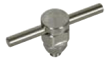 |
KS connector 200 kA | 200 kA lightning current carrying capability according to IEC 62561- 1 2), stainless steel V2A. |
|
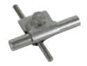 |
MV clamp 200 kA |
200 kA lightning current carrying capability according to IEC 62561- 1 2), stainless steel V2A. Lightning current carrying connection of the air-termination system and down conductor. |
|
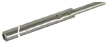 |
Tubular air-termination rod |
Safe interception of the flash charge in permanently corrosionresistant, stainless steel design. |
|
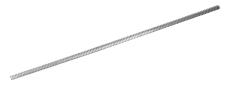 |
Air-termination rod StSt |
Safe interception of the flash charge in permanently corrosionresistant, stainless steel design |
|
| Application | Type | ||
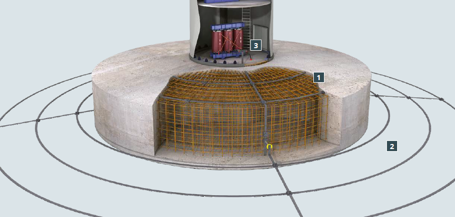
| Foundation Earthing | |||
| 1 | 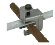 |
Connecting clamps | Clamps for connecting round and flat conductors in concrete foundations and reinforcements with round and flat conductors with tested short circuit current carrying capacity (50 Hz). |
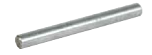 |
Round wire 10 mm St/tZn | Round wire tested to IEC 62561-2 for use in lightning protection and earth-termination systems 3). | |
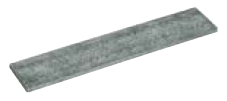 |
Strip 30 x 3.5 St/tZn | Strip tested to IEC 62561-2 for use in lightning protection and earth-termination systems 3). | |
 |
Fixed earthing terminal type M V4A |
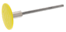
Corrosion-resistant connection of the ring earthing with the foundation earthing at the base of the tower. | |
| Ring Earth Electrode | |||
| 2 |
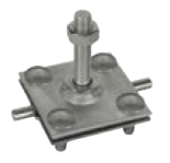 |
Connection clamp with threaded bolt StSt (V4A) |
For connection of round and flat V4A conductors to fixed earthing terminal |
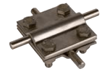 |
Cross unit StSt V4A | Corrosion-resistant connection of the individual ring conductors in V4A. | |
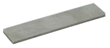 |
Stainless steel strip V4A | Corrosion-resistant ring conductor in V4A. | |
| Equipotential Bonding | |||
| 3 | 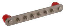 |
Equipotential bonding in the tower base/equipotential busbar StSt |
Suitable for equipotential bonding and protective/functional equipotential bonding. |
Safe service and maintenance work
DEHN safety equipment
Safe Right Down The Line
Work on electrical systems is becoming more and more demanding. Make sure you use safe and reliable equipment. DEHN offers tested products and reliable services which protect your employees from injury caused by arc faults and secure the availability of your systems. This gives you, as the employer, legal certainty.
Safe At Work
- Personal protective equipment and arc flash clothing
- Voltage detectors
- EaS devices
- Fixed ball points
- Arc fault protection systems
| Application | |
| External Lightning Protection | |
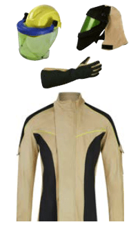 |
Safe when it matters most Reliable protection against arc faults in electrical installations: DEHNcare personal protective equipment keeps you safe from the thermal effects of an arc fault. DEHNcare equipment is also comfortable to wear thanks to the unique material combination of leather and neoprene. The protective equipment is tested to international standards and consists of a hood, safety helmet for electricians, face shield, protective gloves, jacket and trousers or coat. |
| Voltage Detectors | |
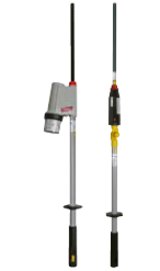 |
Safe right down the line Make sure that no voltage is present with a capacitive voltage detector from 1kV to 420kV. Choose from a wide range of voltage detectors – you are bound to find your voltage and frequency! |
| EaS devices and fixed ball points | |
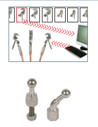 |
Safe earthing and short-circuiting (EaS) Configuring your individual EaS device for your system is simple and flexible. Fixed ball points |
|
Arc fault protection system |
|
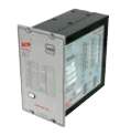 |
Safe – fast – flexible DEHNshort quenches arc faults in your low-voltage switchgear installations in milliseconds. Your employees are safe when carrying out maintenance and repairs. Profit from optimised system availability: your system runs and runs, downtime due to an arc fault is significantly reduced. |
ELECTRICAL SAFETY PROVIDERS
We protect substation engineers, asset managers, SAPS, cable jointers, overhead linesmen and utility workers with PPE and safety equipment: this includes insulating gloves, arc flash clothing, voltage detectors, insulating matting and portable earthing to ensure worker safety when carrying out repair and maintenance on LV-HV switchgear, transformers, substations and turbines.
All of our Cable Connection & Energisation Accessories including Medium & High Voltage joints, terminations, connectors and cleats are tested to the latest international standards and supporting ranges of professional installation tools are stocked to reduce incident, accident and downtime to plant and people.


