

Earthing
AN Wallis Earthing & Lightning Protection | ECA Consultant & Specifier Associate
August 17th, 2020
AN Wallis Earthing
& Lightning Protection
A. N. Wallis & Co. Ltd announce that they are formally linking up with the ECA – the UK’s leading trade association for electrotechnical and engineering services businesses.
A. N. Wallis will become an ECA Consultant & Specifier Associate, providing them with additional engagement opportunities with the trade body and its members.
Earthing and lightning protection manufactured by AN Wallis from high conductivity copper to BS EN 13601 is installed to protect buildings, overhead lines and medium/high voltage substations (MV-HV) against potentially catastrophic damage that can be caused by a lightning strike resulting in short circuiting.
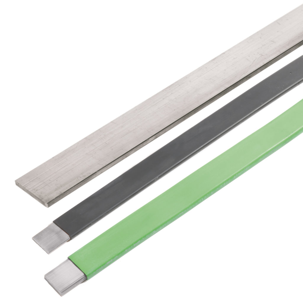
The Wallis product range includes copper earth rods (solid copper, copper bond and stainless steel types), earth bars, copper tape, earth clamps and aluminium tapes.
ECA Director of Member Services Helen Atkinson commented:
“We are delighted to welcome A. N. Wallis as the ECA’s newest Consultant & Specifier Associate. We look forward to working closely with A. N. Wallis & Co. Ltd over the coming period to maximise commercial opportunities and industry collaboration.
“A. N. Wallis & Co. Ltd will now have access to an unbeatable package of resources, and the ability to further engage with the ECA’s membership base, which includes many leading electrotechnical and engineering services businesses.”
The ECA has almost 3,000 members, who undertake a range of electrotechnical design, installation, inspection, testing, monitoring and maintenance work. ECA members range from SME electrical firms to nationwide engineering services businesses, with a combined turnover of over £6 billion annually.
FURTHER READING
- Earth Tape – The Manufacture of Copper Earthing Tapes
- High Voltage Earthing & Grounding System Design Protecting Lives
- Copper Earthing Tape & Rods Protecting 33kV Substation & Transformer Bund
- Substation Earthing

Specialist Distributors: LV, MV & HV Cable Jointing, Substation & Electrical Eqpt
THORNE & DERRICK are national distributors of LV, MV & HV Cable Installation, Jointing, Duct Sealing, Earthing & Electrical Equipment – we service UK and global businesses involved in cable installations, substation, overhead line and the installation of medium/high voltage cable joints and terminations at LV, 11kV, 33kV and HV.
Contact us for 3M Electrical, ABB, Alroc, AN Wallis, CATU Electrical, Cembre, Centriforce, CMP, CSD, Elastimold, Ellis Patents, Emtelle, Euromold, Filoform , Furse, Lucy Electric & Zodion, Nexans, Pfisterer, Polypipe, Prysmian, Roxtec, Sicame, WT Henley.
High Voltage Substation Earthing Using Copper Earth Tape Conductor
May 20th, 2020
A National Grid substation is a large installation where 275kV and 400kV overhead power lines or underground cables are switched and where electricity is transformed to 132kV for distribution to surrounding areas.
National Grid own HV electricity transmission network in England and Wales operating throughout Great Britain. The transmission network is made up of approximately 7,200 kilometres (4,470 miles) of overhead line, 1,400 kilometres (870 miles) of underground cable and around 330 substations.
Substations contain electrical equipment to transform the voltage to lower or higher voltages, switching equipment to connect and disconnect circuits, and protection equipment to ensure the network operates safely and reliably.
Thorne & Derrick are approved vendors to National Grid and their electricity framework contractors. We can deliver customised copper earth tape for high voltage substation earthing embossed to National Grid specification.
Bare copper earthing tape is an integral component of all high voltage substation earthing and lightning protection systems – bare copper, LSF, PVC and green/yellow insulated copper earth tapes are available.
➡ The Wallis product range includes earth rods (solid copper, copper bond and stainless steel types), earth bars, copper earth mats, earth clamps and copper earth plates.

Earth Tapes – Bare & Covered Copper Tapes
Thorne & Derrick are a leading distributor of Earthing & Lightning Protection Systems to the UK power utility industry – we can imprint or emboss copper earth tapes with all UK DNO ownership requirements.
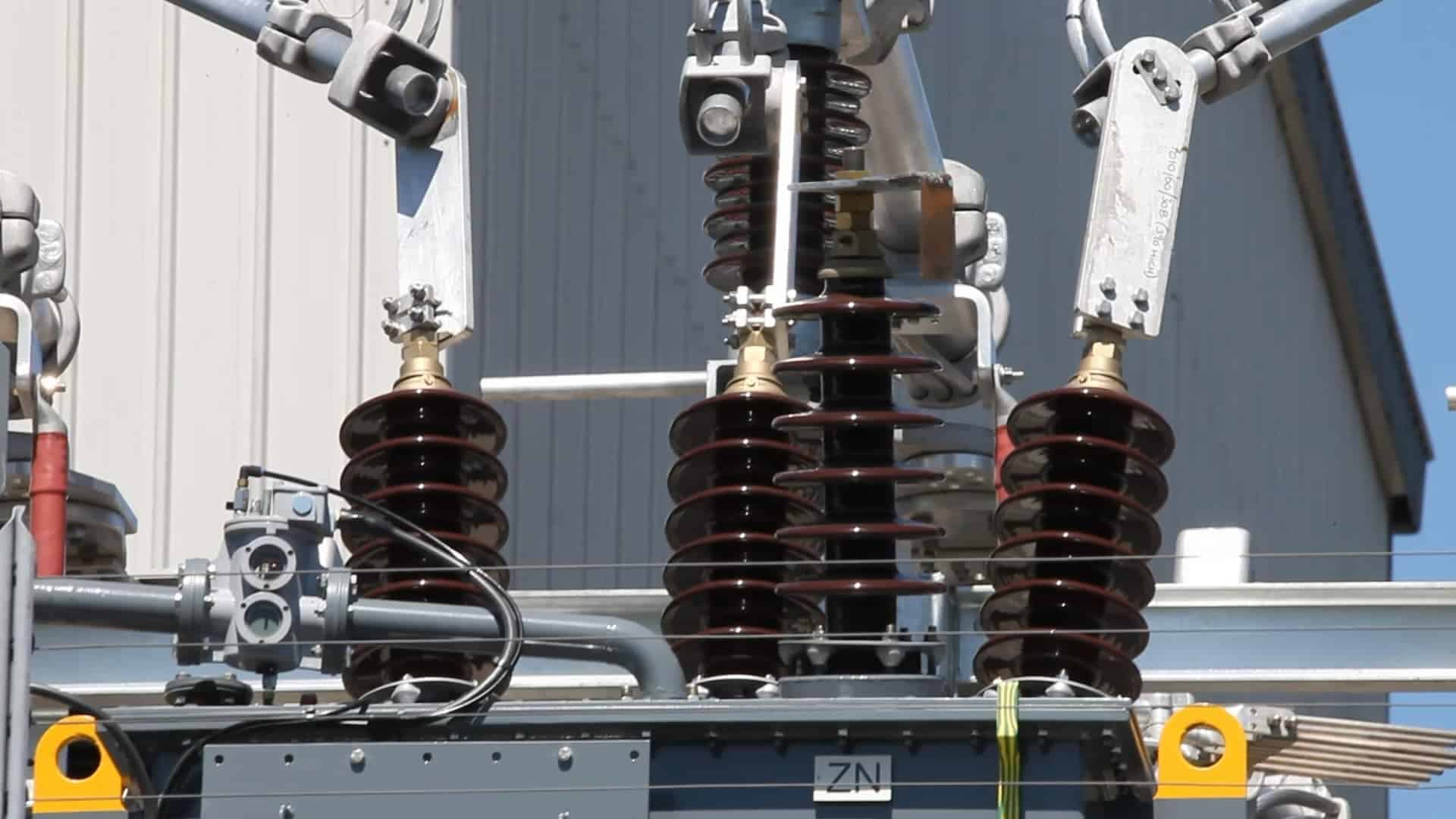
Willesden National Grid 275kV Substation
National Grid Substation Copper Earth Tape : Copper Earth Tape 75mm x 6mm embossed and stamped Property of National Grid. 1,000 metres palletised for despatch today for earthing 400kV Elstree to St John’s Wood substation maintenance projects.
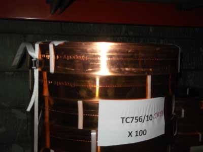
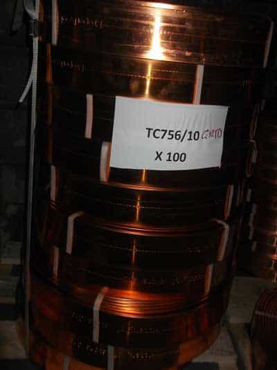
Copper Earthing & Lightning Protection – National Grid
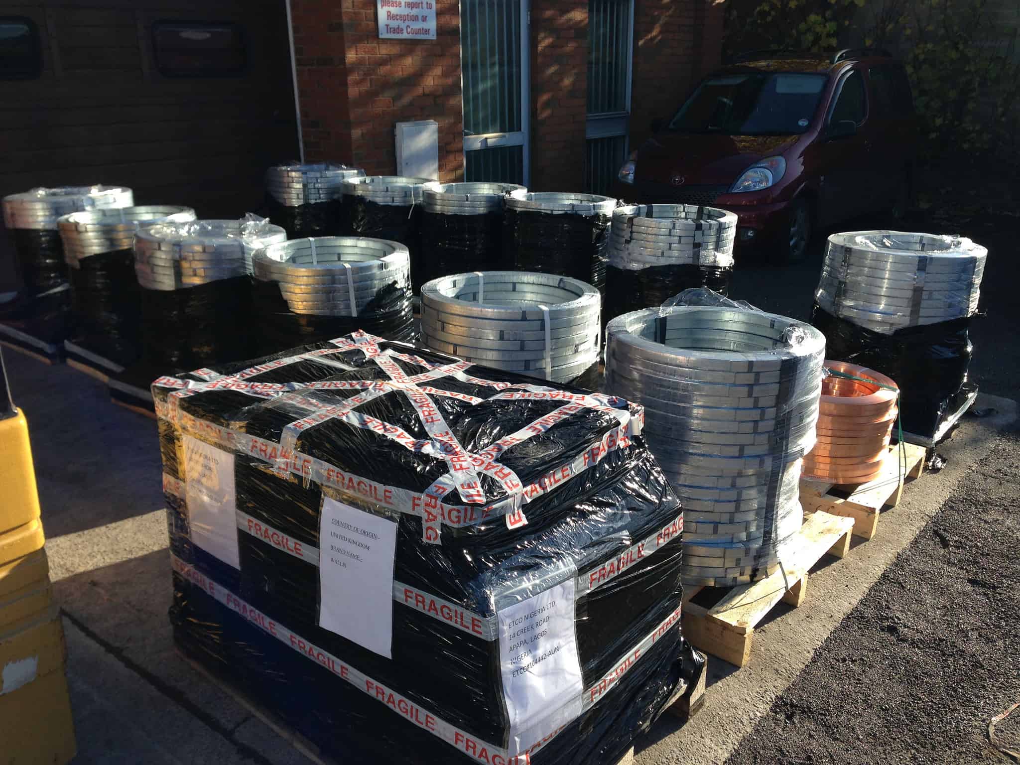
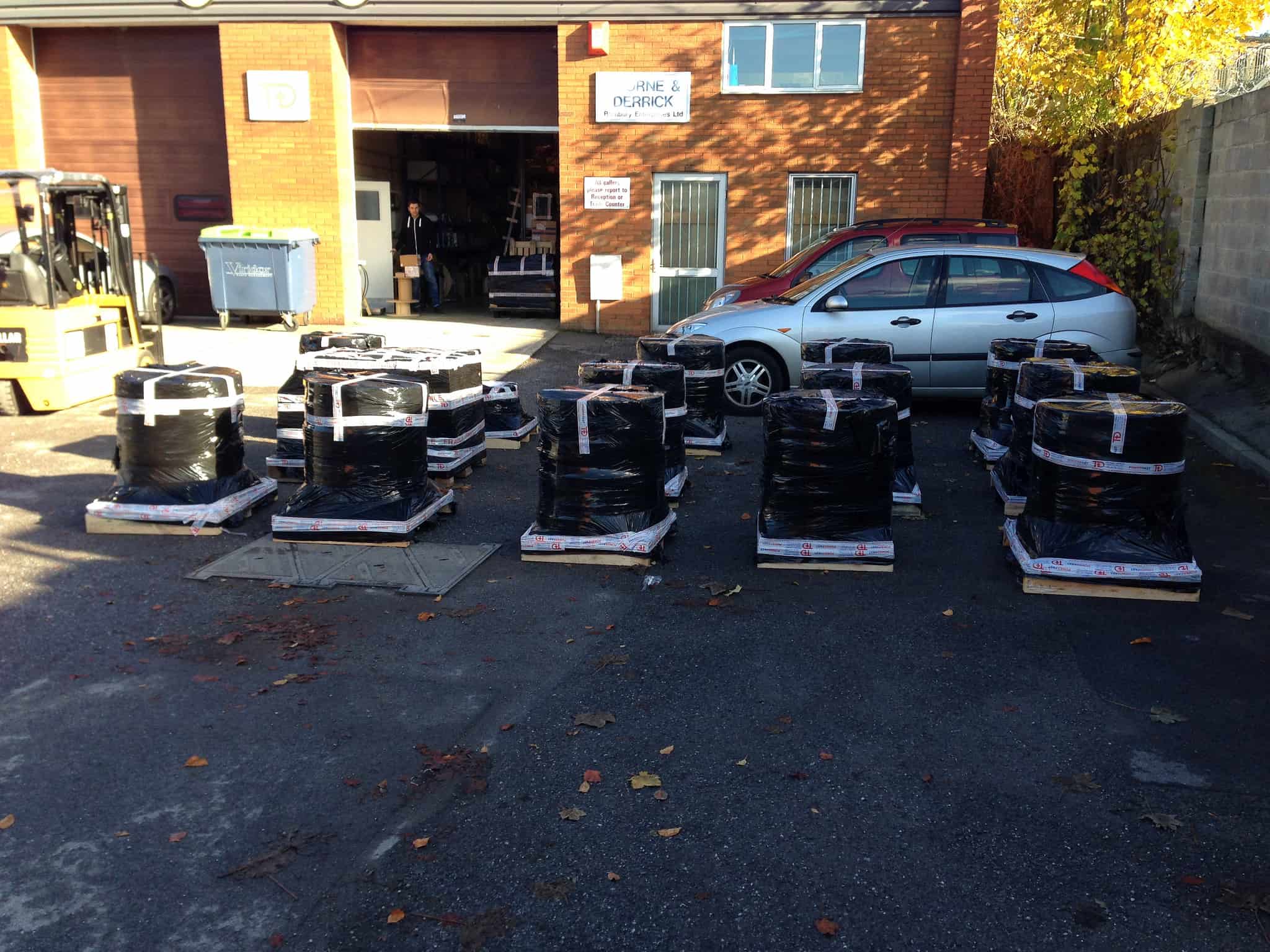
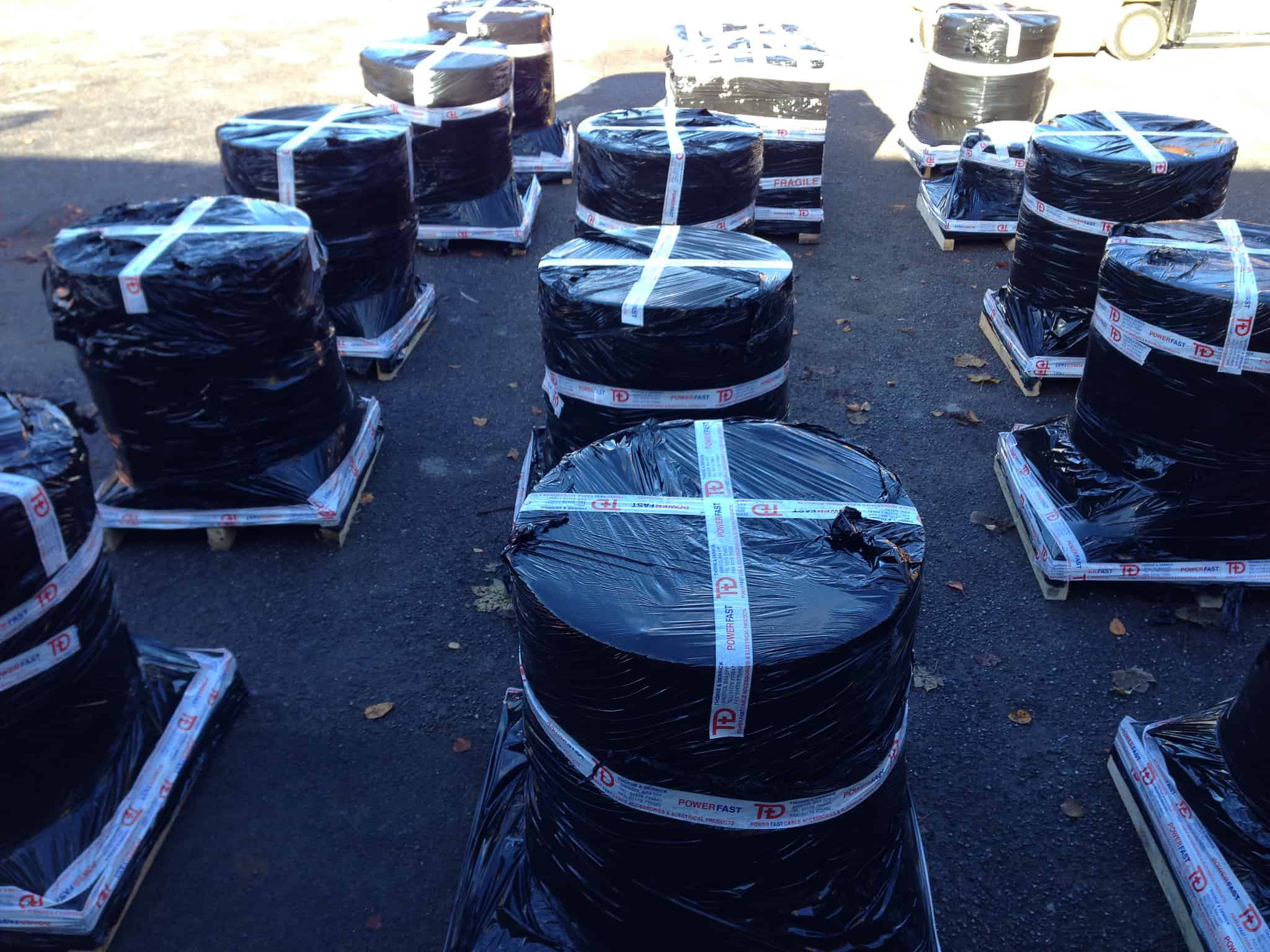
T&D consolidated for despatch a £75K purchase order for Earthing & Lightning Protection Products – the 26 pallet consignment including galvanised steel and copper earthing tapes, mats, rods, earth bars and clamps is destined for several National Grid infrastructure projects including North London Reinforcement, London Power Tunnels & Nemo Link.
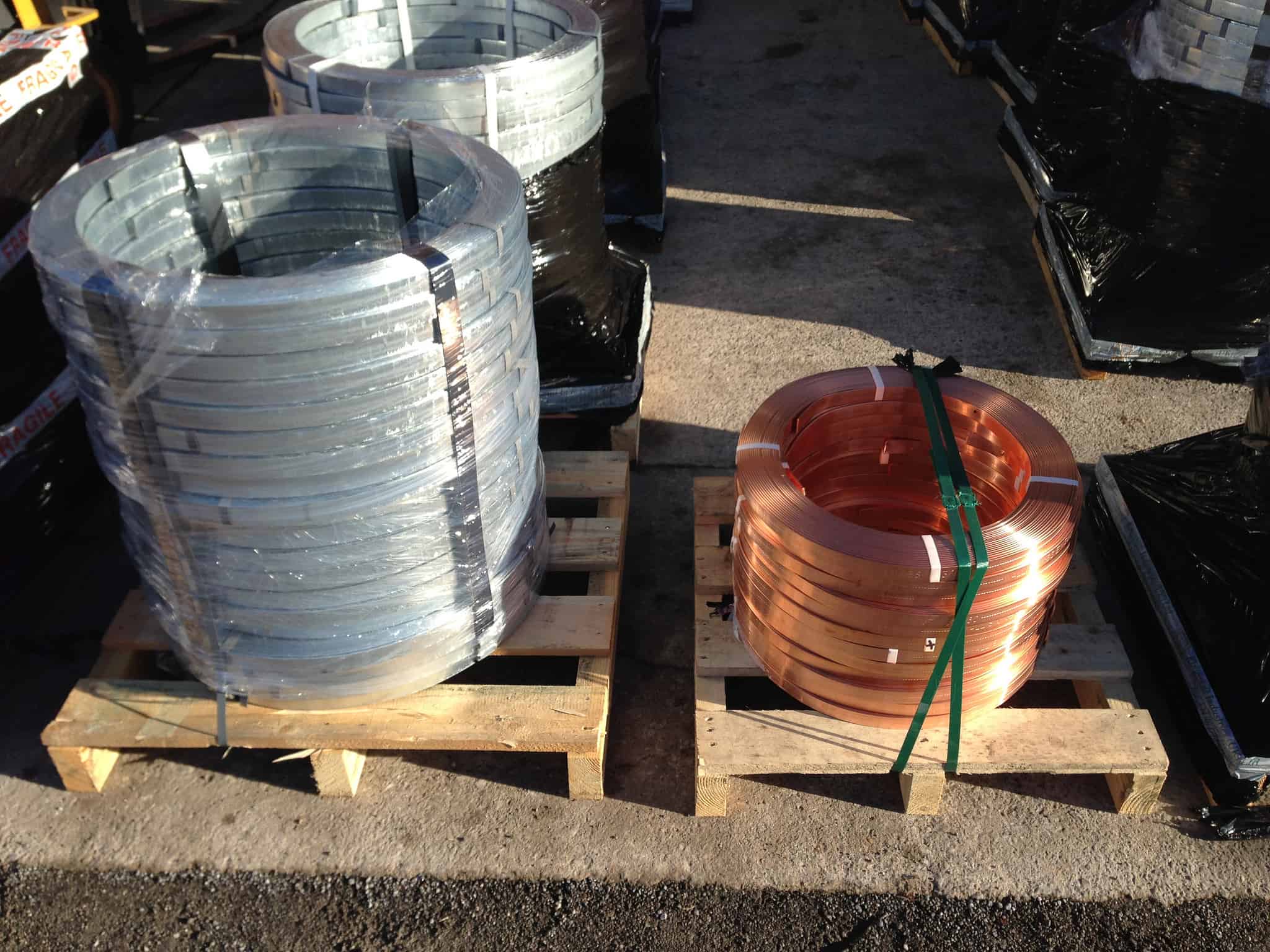
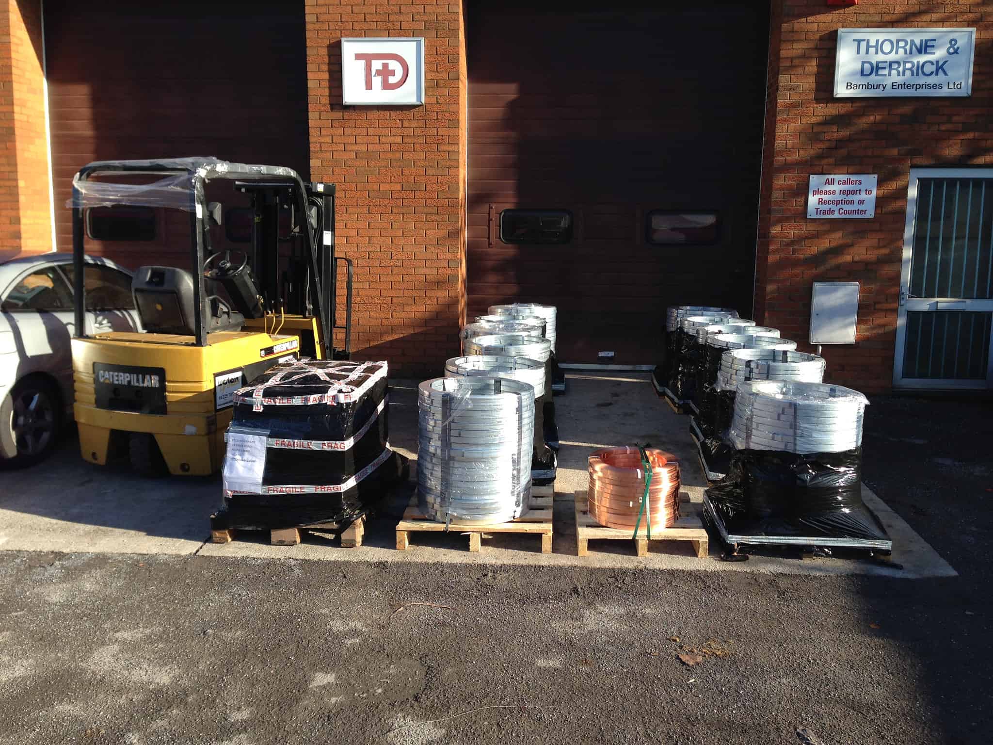
EARTHING GUIDE
Should you require further information or assistance with working on a bill of materials for your earthing requirements, please do not hesitate to contact T&D. Designers of Earthing & Lightning Protection Systems can benefit from downloading our AN Wallis Handbook – an essential resource to ensure compliance with BS EN 62305 the document covers:
- Design of Structural Lightning Protection (BS EN 62305) – Rolling Sphere, Mesh & Protective Angle
- Design of Roof Termination Network
- Copper Tape & Down Conductors – Calculation & Location
- Foundation Copper Earth Rods & Electrodes
Further Reading
Underground Cable Photo Album 1890-1940 – Western Power Distribution (WPD)

Specialist Distributors: LV, MV & HV Cable Jointing, Substation & Electrical Eqpt
THORNE & DERRICK are national distributors of LV, MV & HV Cable Installation, Jointing, Duct Sealing, Earthing & Electrical Equipment – we service UK and global businesses involved in cable installations, cable jointing, substation, overhead line and electrical construction at LV, 11kV, 33kV and EHV.
Contact us for 3M Electrical, ABB, Alroc, AN Wallis, CATU Electrical, Cembre, Centriforce, CMP, CSD, Elastimold, Ellis Patents, Emtelle, Euromold, Filoform , Furse, Lucy Electric & Zodion, Nexans, Pfisterer, Polypipe, Prysmian, Roxtec, Sicame, WT Henley.
HV System Earthing Design – A Case Study
March 27th, 2020
- Republished with Permission of Matthew Taylor – Principal Engineer & Managing Director at Earthing Risk Management Ltd
HV System Earthing Design – A Case Study
Project Brief
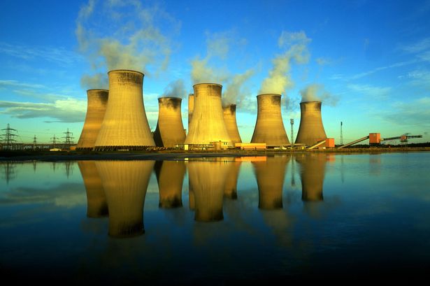
An effective earthing system is vital for large installations such as power stations.
ERM was asked to verify the proposed earthing design against UK standards, including ERM’s previous experience designing the earthing system for the new 400kV connection substation and verifying the designs for the existing 400kV and 275kV substations.
The scale of the site, its varying elevation and the proposed use of a backfill material made this a challenging project.

Challenges
Sheer size; with a site almost a kilometre across, the amount of electrode involved in calculations is taxing for even modern computing with the latest CDEGS software.
Varying surface elevation presented a technical challenge and required the use of specialised functions within CDEGS as well as top-end hardware to process the model and keep calculation times to an acceptable level.
Lateral variation in soil resistivity and significant depths of imported backfill material to be represented in the model. Staged construction of the earthing system in the vicinity of live 400kV and 275kV substations and the provision of 11kV construction supplies present particular safety hazards. ERM was asked to analyse the construction programme and design out any safety hazards associated with the 11kV power network.
Working with multiple companies to progress the project, including international involvement
OUR APPROACH
The size of the power station earthing system, along with the adjacent interconnected sites and requirement to represent a multi layer soil model including backfill representation made the construction and processing of a CDEGS model difficult.
ERM built a bespoke top-end PC to give sufficient processing power to run this model in a timely manner.
Regular liaison with the client throughout the project allowed ERM to understand the breadth of the project including associated areas such as construction techniques and installation methods proposed.
The range of practical and technical experience at ERM allowed us to not only deliver the customer’s requirements but to provide advice value engineering advice, which subsequently provided significant safety improvements and savings in excess of £1M.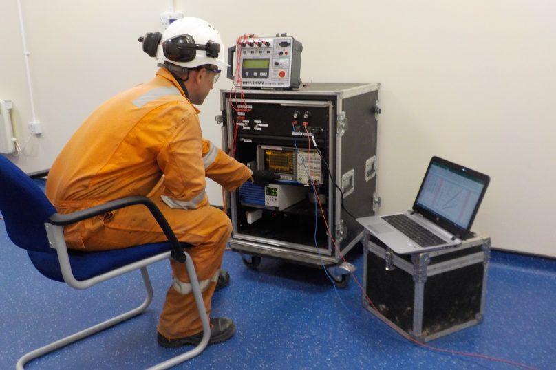
PROJECT OUTCOME / DELIVERABLES
The earthing design was approved from a safety viewpoint and significant cost savings were identified during value engineering both for the design itself and for its construction. The saving exceeded £1M.
Safety hazards with 11kV construction supplies were identified and designed out with a pragmatic solution that required little ongoing management.
The finished product was a detailed model with the functionality required to examine, calculate and draw the above conclusions.
Earthing & Lightning Protection | Earth Tapes | Earth Rods | Earth Bars
meet the company – erm ltd
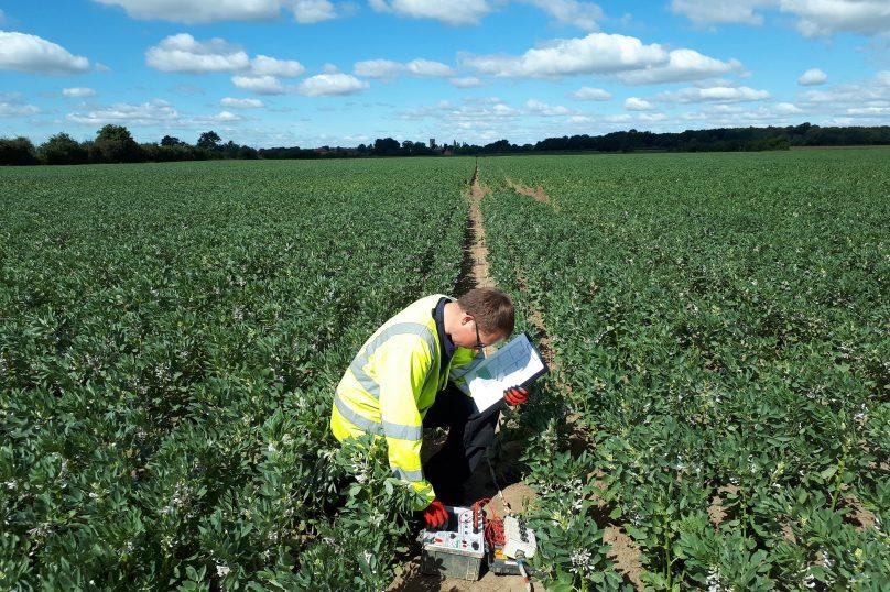
Earthing Risk Management Ltd (ERM) was established in 2002 to address the needs of the Electricity Supply Industry to manage safety hazards associated with HV earthing systems.
Since then, the company has grown to be an established, well respected consultancy serving a broad range of clients.
Employing an experienced engineering team as well as full time site testing teams, they are able to manage, assess and evaluate safety hazards associated with all aspects of HV earthing and lightning protection systems.
ERM’s experts from around the world provide their clients with the highest quality services in earthing design and verification, earth testing and measurements, earthing/lightening protection systems commissioning and test pit reconfiguration, pipeline interference studies, high frequency and transient studies, lightening protection design and upgrade, industry training, quantified risk assessment and fault investigation.
Earthing Risk Management has many years of experience in working with many companies throughout the electricity, gas, rail, and renewables industries trust ERM to deliver solutions for critical infrastructure such as National Grid, DNOs, Mitsubishi and Siemens.
Other Case Studies from ERM Ltd
Fall of Potential Measurement
➡An onshore substation which was constructed as a part of the new extension for an offshore wind farm project, located in the Irish Sea has a capacity of approximately 750MW.
The power from the offshore wind farm is to be exported by undersea high voltage cables to the 400kV onshore substation where the power is fed into the transmission network.
ERM was asked to test the new, onshore substation earthing system to verify the earthing installation and the CDEGS (Current Distribution, Electromagnetic Interference, Grounding and Soil Structure Analysis) model.
Lightning Risk Assessment
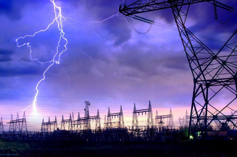
➡ ERM was asked by Uniper Energy to carry out a lightning protection site survey and risk assessment for one of their sites.
Their approach was to attend the site to obtain all relevant information needed to complete the lightning protection risk assessments (LP RA). This information was then passed over to the engineer who could then check that all of the required information was obtained.
This information was entered into specialist software to calculate the lightning risks in accordance with BS EN 62305. Any structures that were above the risk limits were then reassessed with additional lightning protection to reduce the risks to tolerable levels.
The client was provided with a report which detailed the results of these risk assessments and any improvements that they should make to bring the lightning risk levels down.
Accurate lightning risk assessment results were obtained for each of the structures, taking account of existing lightning and surge protection.
Soil Resistivity Measurement
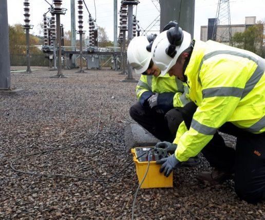
➡ A new overhead line (OHL) was being built between two EHV substations.
The new planned route was in a difficult location compared to the existing route with Earth Potential Rise (EPR) impacts being likely along the strings. As there is potential for significant impacts ERM were brought in to examine the impact of EPR on towers along the routes.
Their experience and information gathering expertise allowed for the identification of Often Frequented Towers (OFT’s) as points of interest along a significant number of tower spans.
This prioritisation allowed for the planning of Soil Resistivity test routes in proximity to these points of interest only and therefore reduce the number of tests that had to be carried out. This allowed for savings on project costs and time taken to produce results.
The project was delivered to the customer outlining the findings of the study in a timely manner. The report made recommendations to the customer for not only the results but for the possible improvement of this, and any subsequent, studies with regards to the information used and alternative approaches to the study.
Contact ERM
Britannia House, Caerphilly Business Park, Caerphilly, South Wales, CF83 3GG
+44 (0)2920 850 444
[email protected]
further reading
- Earth Bars | High Specification Copper Earth Bars for Lightning Protection Systems
- Substation Earthing
THORNE & DERRICK are national distributors of LV, MV & HV Cable Installation, Jointing, Duct Sealing, Substation & Electrical Equipment – we service UK and global businesses involved in cable installations, cable jointing, substation earthing, overhead line and electrical construction at LV, 11kV, 33kV and EHV.
Since 1985, T&D have established an international reputation based on SERVICE | INTEGRITY | TRUST.
Contact us for 3M Electrical, ABB, Alroc, AN Wallis, CATU Electrical, Cembre, Centriforce, CMP, CSD, Elastimold, Ellis Patents, Emtelle, Euromold, Filoform , Furse, Lucy Electric & Zodion, Nexans, Pfisterer, Polypipe, Prysmian, Roxtec, Sicame, WT Henley.

Lightning | An Introduction To Lightning Protection | Networks, Strategy & Systems | Part Two
October 23rd, 2019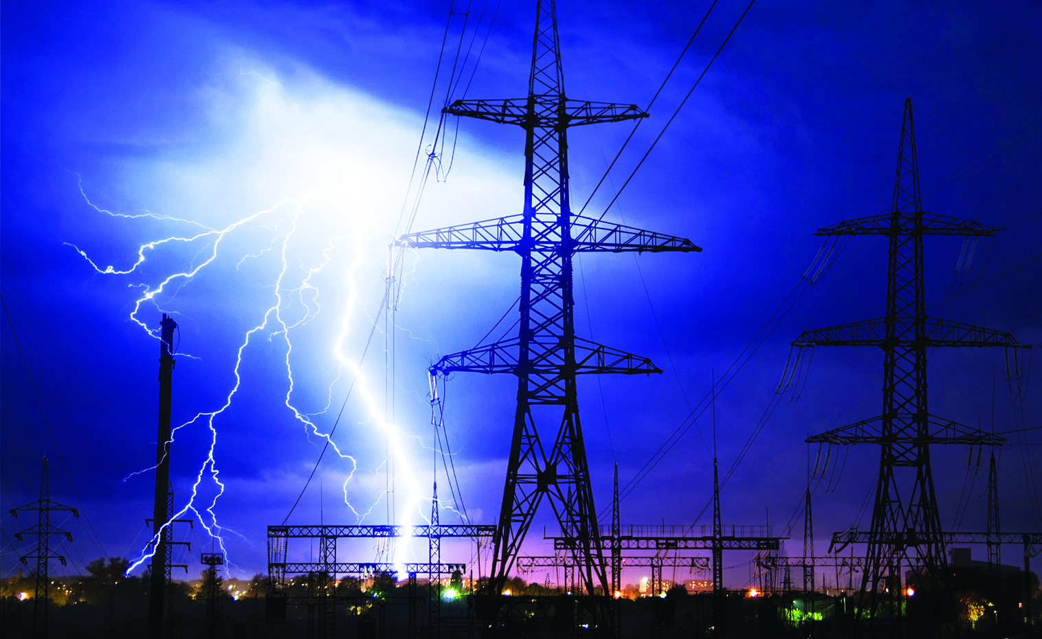
An Introduction To Lightning Protection
-
uploaded by Chris Dodds - Thorne & Derrick Sales & Marketing Manager
Earthing
Lightning Protection
AN Wallis
In the second part of the series AN Wallis gives an introduction to lightning protection focusing on systems, strategies and earth terminations and networks.
➡ Earthing | An Introduction To Earthing & Earthing Designs | Part One
Structural Lightning Protection
Structural Lightning Protection systems are installed to minimise the risk of damage to the external & internal parts of the structure, including the electrical and electronic equipment from a lightning strike and reducing the risk of injury to humans by safely discharging the high voltage to the earth system.
The external lightning protection attracts the lightning discharge and conducts it safely to earth and the internal lightning protection, with use of transient surge protectors, minimises the damage to sensitive equipment and bonding of conductive services ensure a safe path to earth.
A complete Lightning Protection System (LPS) can only be achieved when both safety measures of Internal & External LPS are employed to the structure based on the Risk Assessment.

Lightning Protection System (LPS) JG253 – In-Situ
Lightning Protection Strategy
The normal strategy in achieving protection is to capture the lightning at a preferred point by the use of air terminations and conducting it via low impedance down conductors and earth electrodes to a low resistance earth of less than ten ohms.
Air terminations and down conductors are spaced at regular intervals to form a mesh of conductors around the perimeter of the building and roof, known as a Faraday cage, and are joined together by specially produced damps and fixings or welding.
Lightning Protection System Design Considerations
A LPS is designed according to geographical location, local terrain, soil conditions, size and height of building, type of material used in construction, type of material stored in the building, use of building and is based on established standards for risk assessment.
The Risk Assessment needs to be carried out prior to the design of the structural LPS to determine the Class of LPL required based on the IEC / BS EN 62305 standards or internationally accepted standards.
Air Termination Networks
Based on the determined Class of LPL conductor spacing’s can be selected as identified below:
| Class of LPS | Roof Mesh Conductors W (Width – Metres) | Rolling Sphere Radius r (Radius – Metres) | Protection Angle a (Degree) | Down Conductor Spacing (Metres) |
| I | 5 x 5 | 20 | Refer to chart | 10 |
| II | 10 x10 | 30 | 15 | |
| III | 15 x 15 | 45 | 15 | |
| IV | 20 x 20 | 60 | 20 |
To calculate the areas of protection the Rolling Sphere technique can be employed. The zone of protection determined by the methods requires protection through the Roof Mesh method and Protective Angle Methods.
Roof Mesh Method — Simple and direct implementation of conductor spacing’s based on the Class of LPS, e.g. Class I LPS — Roof conductors are to be spaced in a grid of 5 x 5 metres throughout the flat roof plane.
The Protective Angle Method is based on the relativity between the height of protection required to the prescribed angle of protection in conjecture with the height to be protected which can be obtained from the chart below. Key areas or strike points need to be determined before employing the protection measure.

Class of LPS Graph
Down Conductors
Down conductor spacing has to be in accordance with the Class of LPS which is determined and to be adopted based on the table. E.g. Class I LPS — Down conductors to be spaced at every 10 metres of the structure around the periphery of the structure.
The spacing should be carried out as evenly as possible on the periphery starting at the corners and at the shortest distance to earth.
Sufficient separation distance ‘s’ need to be maintained when down conductors are placed in overhangs and care to be taken to avoid re-entrant loops.
Earth Terminations & Networks
The information contained in this section is primarily for LPS earthing.
For Earth Termination systems two basic types of earth electrode arrangements are applied. Type A earthing arrangement is suitable for low structures and existing structures. Type B earthing arrangement is usually followed throughout.
Each down conductor needs to be connected to an earth electrode to form the earthing with a minimum of two. The minimum length of earth rods that are required to be driven into ground is 2.4 metres. Earthing system contains of horizontal earth electrodes and vertical earth electrodes. Earth rods may need an earth inspection housing for periodic testing of earth resistance.
Resistance to Earth
To maintain a safe earth system, it is recommended that the earth rods to ground resistance values are less than 10 ohms. Earth resistance values are measured at low frequency.
A single earth rod may not achieve the required resistance figure and several may need to be fitted to achieve this; their combined resistance is proportional to the reciprocal of the individual rod resistances to earth.
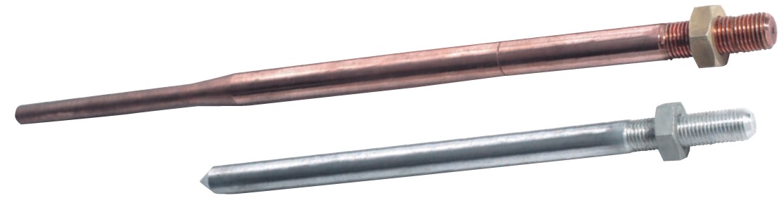
Earth Rods
This rule holds true as long as each rod is situated outside the resistance area of any other. To ensure this is the case, it is generally accepted that the minimum spacing between rods should not be less than their driven length.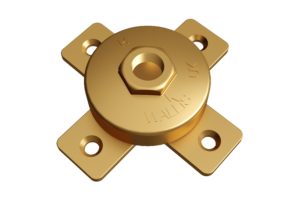
The expected number of rods required to obtain a particular resistance value, e.g. ten ohms, can be roughly calculated.
To do this the soil resistivity needs to be taken into consideration. A soil resistivity test will need to be performed.
There are several methods used to obtain a lower resistance value:
- More rods can be driven. Rods can be driven deeper
- Rods of a larger diameter can be used
- Ring conductors connecting rods together underground can be used
- Where deep driving is not possible shorter rods with a larger diameter can be used; copper earth mats and earth plates can be used in place of earth rods
- A “crows foot” configuration can be used where a parallel connection is not possible
Where high resistance soil conditions are a problem soil conditioning agents can be used to backfill rod holes. Conductive concrete can be used to backfill an earth mat. Both effectively increase an electrodes cross sectional area and therefore reduce its resistance to earth.
The international standards also specify the recommended materials used for all earthing conductors and their dimensions.
Equipotential Bonding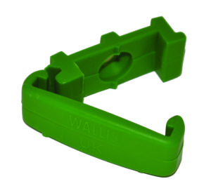
It is common practice to use the buildings natural structural steelwork and bonding it to the LPS to further improve its ability to conduct lightning and fault currents to earth; prior permission may be required.
Joints
Joints should be mechanically effective, all joints other than welded ones are a potential discontinuity, and care should be taken to ensure contact surfaces are clean and that fixing clamps are tight and well protected from corrosion, which can occur if dissimilar metals are joined. Ideally there should be as few joints as possible in an LPS design.
Maintenance & Life of an LPS
It is important to properly maintain an LPS to ensure it retains its ability to conduct the same current carrying capacity as it did when it was originally installed. Earth rod resistances should be regularly checked.
Corrosion and fault currents can cause high resistance joints leading to overheating. However, if an LPS is correctly installed and maintained it should last for many years.
The information contained in this section is intended as a guide and should not be used to perform designs. AN Wallis does not accept responsibility for errors or omissions. Detailed information on LPS design is contained in internationally recognised European and British LPS standards.

Earthing – Copper Earth Tapes | Bars | Clamps | Rods

THORNE & DERRICK
T&D are Specialist Distributors to UK Distribution Network Operators (DNO’s), NERS Registered Service Providers, ICP’s and HV Jointing Contractors of an extensive range of LV, MV & HV Jointing, Earthing, Substation & Electrical Eqpt – this includes 11kV/33kV/66kV cable joints, terminations and connectors for both DNO and private network applications.
Contact our UK Power Team for competitive quotations, fast delivery from stock and technical support or training on all LV-HV products.
Key Product Categories: Duct Seals | Cable Cleats | Cable Glands | Electrical Safety | Arc Flash Protection | Cable Jointing Tools | Cable Pulling | Earthing | Feeder Pillars | Cable Joints LV | Joints & Terminations MV HV

Furseweld | The Furse System of Exothermic Welding
October 9th, 2019
Furseweld | The Furse System of Exothermic Welding
-
uploaded by Chris Dodds | Thorne & Derrick Sales Marketing Manager
Furseweld
The Furse System of Exothermic Welding
Since 1893, Furse has provided world leading Earthing, Lightning and Electronic Systems protection solutions for electrical infrastructure, building services and LV MV HV substations.
FurseWELD exothermic welding is a cost efficient method of achieving high quality electrical connections.
FurseWELD is a simple, self-contained exothermic welding system that uses the high temperature reaction of powdered copper oxide and aluminium, within a mould, to form permanent electrical connections.
Exothermic welded connections are accepted according to the 11kV and 33kV substation earthing design and construction manuals by most UK DNO’s, including UK Power Networks (UKPN) – for instance earth welding copper to copper tape connections and copper tape to stranded cable earthing connections.
Typical Exothermic Welding Applications
- Earthing for power plants and high voltage substations (11kV-33kV)
- Telecommunications
- Transmission and power distribution lines
- Cathodic protection
- Rail connections

Exothermic Wedling Using the FurseWELD System
FurseWELD Earth System Benefits
- Requires no external power or heat source
- Creates high quality electrical connections
- Completely portable
- Can be used safely with minimum training
- Cost effective exothermic welding
- Can be used for over 45 standard connection configurations
FurseWELD Earth Connection Advantages
- Tolerant to repeated fault currents
- Highly conductive
- Does not loosen
- Excellent corrosion resistance
FurseWELD Exothermic Welding – contact T&D for Training & Certification Courses


FurseWELD connections have at least twice the cross-sectional area of the copper conductors being joined or welded, and an equivalent or greater current carrying capacity. Corrosion resistance is exceptional due to the very high copper content (> 90%) of the alloy.

Typical FurseWELD Applications
- Bar to Bar
- Bar to Earth Rod
- Cable to Bar
- Cable to Cable
- Cable to Earth Rod
- Exothermic Moulds & Joints
FurseWELD is suitable for earth rod connections to copperbond, solid copper and stainless steel earth rods – threaded porttion of copperbond earth rods must be removed prior to FurseWELD application.
Welding procedure
- Position the cleaned conductors in the mould after ensuring the mould is dry by pre-heating or making a test joint.
- Lock the mould with the handle clamp; if the mould does not close properly adjust the tension by removing the split pin and turning the eye bolt accordingly. Insert the steel disc into the mould crucible, ensuring it is centred over the tap hole.
- Pour the welding powder into the crucible; the starting powder is retained in the underside of the cartridge and identified by a red cap.
- Spread the starting powder evenly over the welding powder, placing a small amount on the top edge of the mould for easy ignition.
- Close the cover and ignite the starting powder with the flint gun; pull the gun away immediately to prevent fouling the flint. Wait a few seconds to allow the metal to solidify before opening the mould. Remove all slag and dust before making the next weld.
FurseWELD Exothermic Welding Moulds
FurseWELD system of exothermic welding uses moulds to contain the exothermic reaction that creates safe and robust connections. Different types of FurseWELD moulds are available, whose use depends on the requirements of the project.
- Graphite Moulds – Marketleading FurseWELD graphite moulds are extremely robust and capable of creating over 75 connections each.
- Mini-Moulds – FurseWELD mini-moulds are a cost effective alternative to full sized moulds, especially where lower numbers of connections are required. They are smaller overall, less robust and therefore lower priced. Care is required in order to achieve similar service lives to full sized moulds.
- Sureshot – the FurseWELD Sureshot system is a single use ceramic mould supplied complete with retaining disc and powders – It has been designed for use in applications where only a few exothermic welding connections are required.
FurseWELD – How to make a FurseWELD Joint Connection
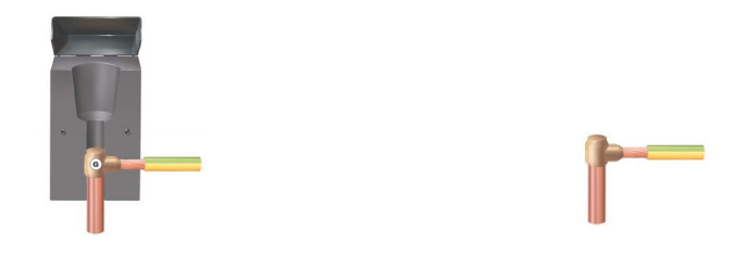
1. Locate the copper conductors to be joined in the FurseWELD cavity and close the mould.
2. Locate the steel retaining disc in the base of the crucible, pour in the weld powder followed by the starting powder. Ignite starting powder with a spark gun.
3. The exothermic reaction reduces the weld powder to molten copper alloy which melts the retaining disc and flows into the weld cavity where it partially melts the conductors
4. The molten copper allow cools to leave a fusion weld of great mechanical and electrical integrity.

FURSEWELD TOOLS / ACCESSORIES

Furseweld Exothermic Welding Tools & Accessories
- Handle Clamp
- Flint Gun
- Toolkits including cable or tape cleaning brush, mould cleaning brush & mould scraping tool
- Gas torch (to preheat the mould)
- Optional toolbox & heat resistant mould jacket
Potential Hazards
As with all forms of welding the potential hazards are:
- Accidental contact with hot work.
- Spatter of molten metal.
- Eye irritation.
- Throat/chest irritation.
Frequently Asked Questions About Exothermic Welding
Could you tell me how many welds can be completed before replacement of the mould is required?
With regards to the Exothermic Welding Mould, the mould should be good for 40-50 joints at a minimum (they could easily do a lot more if they are maintained and used correctly).
Are the earth welding products classed or recognised as “explosives”, and should they be stored in a secure metal box and labelled as explosives?
- FurseWELD materials must be stored in a dry and secure place
- Only take onto site, sufficient materials to give continuity of work
- Fully discuss the operation with the client including site fire precautions. Note: A permit to work system may be required before work can be done
- Wear all of the above listed personal protective equipment and any other equipment which may be required for the job in hand
- Do not use flame or heat near flammable substances or atmospheres; this will include the following: paints, solvents, oils, petroleum, diesel, gasses, paper, rags
What are the training and competency assessments requirements and how often should this training be reviewed, refreshed or renewed?
Furse can offer Exothermic Welding Training and will supply a certificate at the end to show that the user has successfully completed a course of instruction and demonstrated competence in the process. This certificate will last for 4 years – contact Thorne & Derrick for further information.
PPE Requirements?

Safety Goggles & Heat Resistant Gloves
The following should always be worn:
- Safety Goggles
- Heat Resistant Gloves (welders gloves)
- Safety Boots (for site use)
- Safety Helmet (for site use)
- Fire Bucket or Extinguisher (if working near flammable materials)
In addition to the above, other equipment may be required dependent upon the location of and the nature of the job. This may include:
- Fire bucket/extinguisher (if working near flammable materials).
- Heat resistant board (to contain spillage or protect surfaces).
Further Reading
THORNE & DERRICK
Thorne & Derrick are national distributors of LV, MV & HV Cable Installation, Jointing, Substation & Electrical Equipment – servicing businesses involved in cabling, jointing, substation, earthing, overhead line and electrical construction at LV, 11kV, 33kV, 66kV and EHV. Supplying a complete range of power cable accessories to support the installation and maintenance of low/medium and high voltage power systems:
- Slip-on Cable Terminations
- Cold-shrink Cable Terminations
- Heat-shrink Cable Terminations
- Cable Joints – Heat & Cold-shrink
- Separable Connectors (Euromold)
- Surge Arresters & Switchgear/Transformer Bushings
Key Product Categories: Duct Seals | Cable Cleats | Cable Glands | Electrical Safety | Arc Flash Protection | Cable Jointing Tools | Cable Pulling | Earthing | Feeder Pillars | Cable Joints LV | Joints & Terminations MV HV


