

Earthing
Exothermic Welding – 5 Benefits of the Exothermic Weld Connection
November 29th, 2018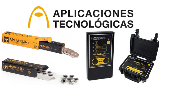
Exothermic Welding
-
uploaded by Chris Dodds - Thorne & Derrick Sales & Marketing Manager
The following table highlights 5 Benefits of using Exothermic Welding systems for Earthing & Lightning Protection when permanently joining copper conductors.
| Mechanical Connection | Exothermic Welding |
| Connection is made by pressing and tightening. Contact connection. | Connection is made by fusion – welding is more reliable and durable. Irreversible molecular bond. |
| Lower conductivity than the copper conductors involved. | Conductivity equal to or greater than the copper conductors involved. |
| Transient connection. Electrical degradation over time. | Permanent connection. Lifetime equal to that of the earthing system. |
| Suffers with the flow of current, faults or repetitive discharges. | Able to withstand repeated current flow without degrading. Minimum maintenance. |
| Connection depends on the tightening torque applied by the installer. | Once the exothermic welding mould is closed the process is autonomous, reproducible and uniform. |
Exothermic Welding
AT3W & Thorne & Derrick
Thorne & Derrick are working with AT3W to introduce and develop specifications and business for the Apliweld Secure+ exothermic welding system.
Jason Leatherland (UK Manager AT3W) comments, “having worked successfully together with Thorne & Derrick in the past, I was keen to demonstrate and discuss this product system with them as I knew they would be best suited to showcase the system, and in particular, its increased health and safety benefits, to the most relevant sectors in order to increase the users efficiency and reduce the potential of site accidents from exothermic welding.”
Jonny Hewitt (T&D UK Power Team) added, “working with the UK DNO’s and their preferred ICP’s we look forward to further developing relationships and presenting the exothermic welding system to existing and new clients. We will be working closely with AT3W to introduce the product to market and improve worker and site safety in the utility industry.”
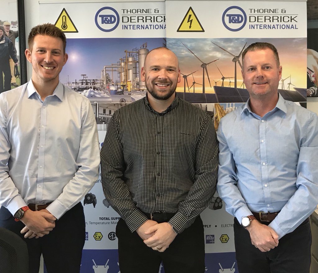
Pictured: Jonny Hewitt (T&D) with Jason Leatherland and Chris Dodds (T&D).
💡 HV Earthing & Lightning Protection Training Courses go to ➡ Online Training Resource provided by Ian Griffiths, Principal Engineer at GreyMatters. Ian is an Earthing & Lightning Consultant of 27 years, one of the top 1% UKAS accredited CDEGS consultants and professional advisor to international utility companies, data centre and infrastructure developers. See our Blog to learn more about GreyMatters and High Voltage Earthing.
LV MV HV Cable Accessories & Substation Electrical Equipment
Thorne & Derrick are Specialist Distributors of leading manufacturers of Cable Accessories, Substation Earthing, Jointing & Installation Equipment.
LV MV HV cable accessories from stock used to joint, terminate, connect, cleat and gland power cables to air and gas insulated substations, transformers, switchgear and overhead line networks.
LV 600/1000V ◊ MV 11kV 33kV ◊ HV 66kV 132kV
 |
 |
 |
 |
 |
 |
 |
 |
 |
 |
Marconite – Electrically Conductive Earthing Compound
November 14th, 2018
Marconite
-
uploaded by Chris Dodds - Thorne & Derrick Sales & Marketing Manager
Low Resistance Earthing Compounds
for Substations
Marconite is developed and manufactured specifically for use in electrical earthing installations enabling electrical engineers and earthing system designers to achieve permanent, stable and low resistance earthing solutions even in difficult ground or soil conditions – typically used for substation earthing applications.
Adding Bentonite and similar earthing compounds, such as Marconite, in a trench or larger drilled hole around the electrode, typically an earth rod, has the effect of increasing the surface area of the earth conductor, assuming the resistivity of the added material is lower than that of the surrounding soil.

Earthing Compunds
Marconite compound is a precisely measured, granular material, dark grey in colour, that is virtually dust free and with exceptional electrical properties.
| Marconite Earthing Compound Benefits | |
| Low Resistivity | 0.001 ohm.m is extremely low when compared to Bentonite’s 3 ohm.m |
| Versatile | Suitable for most ground conditions and becomes a permanent, solid structure that it is not prone to shrinking, drying out or being washed away |
| Cost Effective | It is a permanent solution; there is no need to remove and replace or ‘maintain’ it with additional water / salts every few years in order to achieve the desired earth values |
| Chemically Inert | Is non-corrosive to steel or copper, does not attack cement structures and has a pH within the neutral range |
| High Strength | Can be used as part of the building structure itself and can achieve strengths higher than Grade 25 concrete |
| Easy To Use | Forms a concrete like material that from first pour, achieves a low resistance earth, no need to wait or return to test |
More About Marconite
Marconite is essentially a conductive concrete in which a carbonaceous aggregate replaces the normal aggregate used in the conventional concrete mix – Marconite earthing compound has some similar properties to Bentonite, i.e. causes minimal corrosion with certain metals and has a low resistivity. It was developed as a process which started in 1962 when Marconi engineers sought a material which conducted by movement of electrons rather than ions. It contains a crystalline form of carbon and the overall material has a low sulphur and chloride content.
There is stated to be some corrosion of ferrous metal and copper whilst the Marconite is in slurry form, but it is suggested that a thin protective layer forms. When the concrete has set, corrosion is said to cease. Metal should ideally be painted with bitumen or a bitumastic paint as it enters the Marconite structure to prevent corrosion at this point. Aluminium, tin coated or galvanised steel should not be installed in Marconite.
When Marconite is mixed with concrete, its resistivity can fall to as low as 0.1 Ohm-metre. It will retain its moisture even under quite dry conditions so has been used in the hotter climates as an alternative to Bentonite compound. Its principle application in the UK is at locations where theft or third party interference is likely to be a problem, or to enclose copper electrodes in bore-holes or voids within rock when driven into the ground.
When surrounding an earth rod with Marconite which has been installed in rock, the resistance of the copper earth rod will be reduced as the volume of Marconite used is increased. For example, if a 1 metre earth rod is installed at the centre of a hemisphere of Marconite of radius 1.5m, it would have a resistance of approximately 2,000 Ohm if the surrounding rock is of 2,000 Ohm-metres.

Call T&D for Copper Earthing Tapes | Best Prices | Large Stocks
If the radius of the hemishere is increased to 3 metre and then 5 metre, the resistance would fall to 1,080 Ohm and 650 Ohm respectively. Because of the prohibitive cost of removing such a volume of rock, it makes sense to make use of existing cavities for this purpose, where possible. Also, the void is likely to be part filled with other materials (such as concrete) to reduce the amount of proprietary material required. Marconite is normally considered as having a resistivity of 2 Ohm-metres.
T&D provide fast delivery and competitive prices for genuine Marconite brand earthing compounds.
Marconite – Electrically Conductive Aggregate Material
SUBSTATION EARTHING & MV HV CABLE JOINTING
To complement Earthing & Lightning Protection & Exothermic Welding products we stock and distribute the most extensive range of copper earthing equipment.

Marconite Earthing – Conductive Concrete, Mixing & Use Of Marconite
November 12th, 2018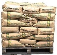
-
uploaded by Chris Dodds - Thorne & Derrick Sales & Marketing Manager
Marconite is the world’s leading premium electrically conductive backfill material which significantly enhances the effects of copper earth electrodes to reduce the resistance of a lightning protection or copper earthing system.
Marconite is a dark grey, granular material that replaces traditional sand and aggregate materials used within concrete mixes – it should be mixed in the ratio of 3 parts of Marconite to 1 part cement by weight with addition of 1 litre of water per 4kg of total mix:
Mixing Marconite
3 x 25 Kg bags of Marconite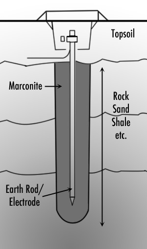
1 x 25 Kg bag of Cement
25 litres (25 Kg) of Water
Ground enhancement materials such as Bentonite and Marconite earthing compounds are used to lower the resistance to earth of Earthing & Lightning Protection Systems – simple to install and used as backfill for earth electrodes, including earth rods or earth mats.
When mixed as described above, the Marconite forms a relatively dry material with an ‘as poured’ density of around 1300 Kg / m³ for earthing purposes.
The water content may be adjusted as the application requires, but this will affect the concretes final compressive strength and the drying times accordingly.
Typically Marconite concretes are touch dry within hours but can be several days before being fully cured.
Marconite is chemically inert with very low soluble sulphate content. It can be used with all conventional types of cement, as well as most proprietary resin-based cements, adhesives and gypsum plasters – due to the inert structure Marconite is non-corrosive to steel or copper and with a pH level in the neutral range will not degrade or erode cement structures.
Marconite Conductive Concrete is a registered product of the James Durrans Group and is solely produced by their subsidiary company Carbon International Limited.
Resistivity of Marconite
Marconite earthing aggregate provides exceptional resistivity with a resistance level of .001 ohm.m – even when mixed with cement the resulting resistance level is only 0.19 ohms.m.
Reducing Earth Electrode Resistance
Marconite is a conductive carbonaceous aggregate which, when mixed with conventional cement, has the effect of increasing the surface area of the earth electrode, thus helping to slightly lower its resistance. These earthing back-fill materials can provide a significant improvement to earthing system performance but also provide several secondary functions: maintain the resistance value at a more constant level throughout the year, to provide protection against 3rd party damage, or to protect the earthing electrode from corrosion.
Marconite is also useful for surrounding electrodes installed in rock.
Where a decision is taken to use FurseCEM, Bentonite, Marconite or any other special back-fill material, the design engineer should ensure that this information is passed to the construction staff – construction methods can be used to limit the amount used and therefore associated cost.
Examples are mixing Bentonite with local clay, reducing the hole diameter drilled (for vertical copper electrodes) and minimising the width and volume of the horizontal trench section into which the earth electrode will be installed.

Contact T&D for Copper Earthing Tapes – Bare Tape & Covered
Marconite – Electrically Conductive Aggregate Material
SUBSTATION EARTHING & MV HV CABLE JOINTING
To complement Earthing & Lightning Protection products we stock and distribute the most extensive range of copper earthing equipment.
FurseCEM Earthing Conductive Aggregate Concrete
November 12th, 2018
-
uploaded by Chris Dodds - Thorne & Derrick Sales & Marketing Manager
FurseCEM
FurseCEM is an earthing conductive aggregate concrete, manufactured by Furse, offers a convenient and permanent solution to Furse earthing problems by obtaining a reliable earth resistance even in installations that require a very low resistance regardless of ground conditions – this includes low LV, medium MV and high HV substations.
A conductive concrete is formed when FurseCEM is added in place of sand and aggregate. This electrically conductive medium has many applications in the electrical/construction industry including RF and microwave screening, static control and of course earthing for which it was specifically developed.

FurseCEM concrete used as a backfill for conventional earth rod to achieve a lower earth electrode resistance
When used as a backfill for an earth electrode or earth rods, FurseCEM impregnated concrete greatly increases the electrodes’ surface area. For example, increasing the effective diameter of a copper earth rod from typically 15mm to 200mm, could lower its resistance to earth by as much as 50% (see graph below).

Resistance versus Diameter
FurseCEM Features & Benefits
- Permanent earth reading – resistivity that will remain constant over the life of the installation without the requirement for maintenance
- Constant volume – regardless of water content, FurseCEM will not shrink or expand, thus maintaining constant contact between the earth electrode and the soil
- Cost effective – reduces drilling, saves on earthing materials, and requires no expensive maintenance
- Non leaching – FurseCEM is a conductive concrete and therefore cannot be washed away
- Chemically inert – completely non-corrosive, and will not in any way damage earth electrodes, steelwork or concrete
- Fast drying properties – allows for quick and easy installation
- Mechanical strength – provides high compressive strength where required
- Long shelf life – can be stored for long periods without deterioration
- Versatile installation – suitable for use in boreholes and trenches

FurseCEM Earthing Conductive Aggregate Concrete
Earthing Conductive Aggregate Concrete
FurseCEM Part Numbers
FurseCEM should be mixed in a 3:1 ratio by weight (not volume).
| Description | Sack Weight | Part Number |
| FurseCEM | 25kg | CM025 |
| FurseCEM (supplied with cement) | 25kg | CM030 |
Contact T&D for Copper Earthing Tapes | Large Stocks | Best Prices
FurseCEM versus other methods of earth improvement
Chemical solutions — such as copper sulphate, sodium carbonate, calcium sulphate and sodium chloride (table salt) mixed with charcoal are sometimes poured into the ground to improve earth readings, but these have the disadvantages of:
- being required in large quantities to make a difference
- requiring constant moisture to remain effective
- drying out if moisture is not present
- eventually leaching out of the soil, returning the earth to its former high value, unless regularly and expensively maintained
- causing corrosion of the earth electrode system and deterioration of concrete (particularly relevant to transmission towers).
Chemical earth rods — perforated metal tubes packed with a with a chemical compound are also sometimes used but these:
- are costly
- are subject to leaching or washing away of the chemicals unless maintained
Bentonite — and certain other compounds intended to absorb and retain moisture in and around an earth electrode.
- rely on constant moisture to maintain volume and hence work effectively
- without moisture, drying and shrinkage occur, causing loss of contact with the surrounding soil and a deterioration in the earth reading
- regular checking and/or maintenance may be required
FurseCEM is a non-corrosive permanent solution to earthing problems, providing a fixed earth reading that will not very significantly regardless of seasonal factors, and without maintenance.
SUBSTATION EARTHING & MV HV CABLE JOINTING
To complement Earthing & Lightning Protection products we stock and distribute the most extensive range of copper earthing equipment.
Further Reading
How to Size High Voltage Earthing Conductors Correctly
October 15th, 2018
A Guide To High Voltage Earthing Conductors
-
Guest Blog by Ian Griffiths - Principal Partner at GreyMatters
What size earthing conductors should I use?
And, is there a simple table I can use for this high voltage earthing design?
These are great questions that I’m often asked. This post answers these questions together with the choice of conductor materials and jointing method within a high voltage earthing design project.
Assessing conductor size is entirely dependent on the electrical configuration and the load that the conductor must take. For example, an above-ground bonding conductor serves to transfer current with minimal voltage drop, from A to B.
A directly buried conductor has an additional purpose, that of leaking the fault current/voltage into the local geology (as part of an electrode).
When considering Lightning, the same conductor above might also see a high-frequency component and which will impose yet another requirement.
High Voltage Earthing Conductors
Design Considerations
In IEEE-std80ƒ Guide for Safety in AC Substation Grounding, section 11 – states the basic requirements are:
Each element of the grounding system, including grid conductors, connections, connecting leads, and all primary electrodes, should be so designed that for the expected design life of the installation, the element will
a) Have sufficient conductivity, so that it will not contribute substantially to local voltage differences.
b) Resist fusing and mechanical deterioration under the most adverse combination of a fault magnitude and duration.
c) Be mechanically reliable and rugged to a high degree.
d) Be able to maintain its function even when exposed to corrosion or physical abuse.
Earthing Materials
Copper has traditionally been the go-to material for years in high voltage earthing because it is not only highly conductive but also resistant to most sources of in-ground corrosion.
Similarly, aluminium has sufficient conductivity but suffers from in-ground corrosion, and the oxidation that forms around its surface is not conductive, therefore, compromises the conductor’s ability to leak current when buried, which is why buried aluminium conductors is a no-no.
Stainless steel or mild steel (when appropriately coated – galvanised or copper bonded), on the other hand, may not have the conductivity of copper or aluminium but it is sufficiently conductive to be utilised as a buried conductor.
Dealing with the Heat
So now we’ve covered the materials that are widely used for high voltage earthing.
Point ‘b’ from IEEE-std 80 above calls for the conductor to retain its mechanical strength when being exposed to a fault.
Conductors get hot when current flows through them. And they will potentially be at their hottest when subjected to a fault from the electrical system. This fault means the conductor needs to maintain its physical integrity as temperature increases and not transform into a shower of hot molten metal!
Up to this point, we’ve discussed conductor conductivities, materials and thermal-mechanical characteristics.
Another consideration for high voltage earthing is the method of the joint between conductors.
Conductor Joints
Joints in conductors are as critical to current-flow as the conductors themselves. The jointing method must not allow the joint to introduce excessive resistance. Therefore, the selection of the jointing method will impact the earthing system’s thermal resilience massively. This thermal resilience is why welded joints are the go-to choice for the high voltage earthing system.
Welded joints achieve the nearest physical match to the native conductor itself and are the gold-standard in conductor jointing because they accomplish a molecular similarity to the native material’s conductivity, as well as similar mechanical robustness.
Here’s an example of a safe method of igniting an exothermic weld.
A Word of Caution
Bolted joints and clamps are made up of multiple parts which can creep and loosen over time. Loosening will add resistance across conductor joints, which as previously mentioned… is not a good thing (thermal runaway is a topic for another day).
Bolted joints fall into the category of mechanical joint methods and have a derating factor to keep the conductors operating at lower temperatures. When designing a high voltage earthing system, this means the seemingly unrelated selection of jointing method will also impact the conductor size calculation.
IEEE adiabatic equation
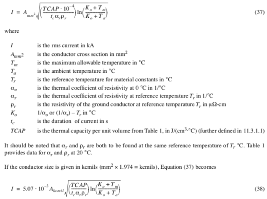
Calculating High Voltage Earthing Conductors
In Summary
So there you have it. Without going into great detail, the following factors influence conductor sizing:
- The magnitude and duration of fault current (i.e. the heat source)
- The method used for the joint
- The conductor material
- The conductor’s role in the high voltage earthing design
These factors may vary project by project, so, using a particular size of the conductor on a previous project does not mean that the same will apply to the next project, which means calculating conductor sizes (adiabatic equation) to fit the particular requirements of the project is usually very necessary.
ƒ IEEE P80 – Guide for Safety in AC Substation Grounding
This guide is primarily concerned with outdoor ac substations, either air-insulated or gas-insulated. With proper caution, the methods described herein are applicable to indoor portions of such substations, or to substations that are wholly indoors. No attempt is made to cover the grounding problems peculiar to dc substations. A quantitative analysis of the effects of lightning surges is also beyond the scope of this guide.
Further Reading
- High Voltage Earthing & Grounding System Design Protecting Lives
- Safer Exothermic Welding With Apliweld Remote Electronic Ignition
- Data Centre Earthing
Ian Griffiths CEng, MBA, BEng, MIET
Principal Engineer at GreyMatters, an Earthing & Lightning Protection Consultant of 27 years, one of the top 1% UKAS accredited CDEGS consultants and professional advisor to international utility companies, data centre and infrastructure developers. Risk Assessment Surveys and measurements for substation earthing or generation schemes on your electrical earthing system, voltages from 1kV to 765kV are undertaken by their highly qualified engineers.
Some LinkedIn Comments
Charles Shannon Senior Application Engineer at IMCORP
Hey Chris Dodds and Ian Griffiths – Substation Earthing. Great subject. I would add two minor clarifications to that blog. #1 when mentioning buried earthing conductors it’s worth clarifying that is for unjacketed cables. Additionally there in the maximum energy calculation note that with proper surge arresters this energy can be significantly reduced which can significantly reduce the size and thus the cost of the cable.
Ian Griffiths – Substation Earthing
Hi Charles, you might be right to add an additional clarification re buried conductors. Still, the piece is intentionally brief (so it’s not intended to be a definitive reference covering all the nuances), still, it does make the clear distinction between above-ground and below-ground conductors to try and get people to think about there being TWO differing purposes that an identical-sized conductor can have i.e. to either leak current (into the geology) or to transfer it (equipotn)… or a combination of both – Oh, that’s 3 but hey. So, for the sake of simplicity, it might be better to leave coatings for another blog 😉
Earth Mats | Earth Plates | Earth Rods | Earth Bars | Earth Tapes | Exothermic Welding from T&D, The Earthing Equipment & Lightning Protection Eqpt. Distributors


