Uploaded by Chris Dodds - Thorne & Derrick Sales & Marketing Manager
Copper Earthing Tapes
Thorne & Derrick International, a leading stockist and distributor of copper earthing tapes manufactured by AN Wallis and ABB Furse provide an overview of the role and relationship of earth tapes and air rods with respect to the design of Lightning Protection Systems for Roof Termination Networks in accordance with British Standard BS EN 62305.
Roof Termination Network
The roof termination network can be concealed below the tiles or cladding provided the air rods/strike pads protrude above the tiles or cladding (see below Figure 15).
Air rods to be selected based on the protection angle method. Strike pads should be provided in accordance with mesh spacing.
The air termination system will usually consist of air rods, flat tape conductors such as copper earthing tapes in a mesh or in some designs a catenary wire (in case of isolated LPS), there are three methods for the earthing system designer to determine the air termination system in the LPS, each is acceptable to BS EN 62305.
The earthing design comes from one of three options already detailed: the rolling sphere, protective angle or mesh alternatives, each method has different criteria for the roof network.
Wherever possible the air termination network should be located:
At the corners of the building
At the most exposed points of the building
As close to the edge of the building as possible (on the parapet wall is usually as close as you can get)
The roof network should follow the most direct route with minimal bends. Where roof tiles are non-conducting the air-termination conductor may be placed either under, or over the roof tiles (over is always preferable), Where the conductor is sited below the tiles vertical finials or flat strike plates should be used These should be spaced at not more than 10 metres for air rods and 5 metres for strike plates (corresponding to class of LPS).
Roof Termination Network concealed below the tiles or cladding provided the air rods or strikes pads protrude above the tiles or cladding
In circumstances where two horizontal LPS air-termination conductors are placed parallel above the horizontal reference plane, the distance that the rolling sphere penetrates below the level of the conductors within the space between the horizontal conductors is:
Where
p = penetration distance r = rolling sphere radius
d = distance between the two parallel air terminal
rods or conductors
The penetration distance (p) should be less than the height of the air terminal/conductor above the roof surface/ reference plane, (ht), minus the height of objects to be protected.
[BS EN 62305-3, E4] p = r — (gr2 – (d/2)2
Protection For Open Roof Car Parks
Open Roof Car Park Protection
For car park structures where the roof is an open parking area (as shown in Figure 17) for cars, normally surrounded by a parapet wall, it is not advisable to have any kind of roof conductors as they are constantly being driven over and walked upon.
In these circumstances the standard allows the use of air rods on the parapet wall with a mesh on the roof hidden between the edges of adjoining slabs or bedded in the concrete with strike pads installed visible above the tarmac or concrete.
Persons and vehicles on this parking area are above the Lightning protection system and not protected from lightning.
If the top level of the car park has to be protected then air rods, catenary wire and natural masts such as lamp posts can be designed in to provide an enhanced protected area.
The step and touch potential risk on the top level of the car park can be overcome provided the roof is constructed of reinforced concrete with interconnected reinforcement steel with continuity provided by welding or clamping.
Conductive fixtures on the roof
Conductive roof fixtures such as AC units outside the zone of protection can be ignored if their height is under 300mm or if it’s under 1 mtr/2 or it’s less than 2mtr long.
Non conductive roof fixtures outside the zone can be ignored if less than 500mm in height.
A conducting fixture such as pipes or an air conditioning unit needing protection should be protected by an air termination system Figure 18. If this is not possible insulated parts, with lengths corresponding to at least twice the specified separation distance, can be installed on the conductive installations. [BS EN 62305-3, E5.2.4.2.4]
Conducting fixtures such as pipes or air conditioning units should be protected by an air termination system
When a non-conductive chimney falls outside the protective zone of the air-termination system, it should be protected by means of air-termination rods or air-termination conductors. The air termination rod on a chimney should be of such height that the complete chimney lies within the protective space of the rod.
[BS EN 62305-3, E 5.2.4.2.4]
Metal roof fixtures should be bonded to the air termination system when the necessary clearance for conformity to the separation distance cannot be maintained.
[BS EN 62305,3, E5.2.4.2.4]
Conductive electrical appliances and fittings on the roof are some of the most difficult problems facing the designer of the LPS if the requirements of BS EN 62305-3 are to fully met and the system be fully compliant. See Figure 19.
To fully comply with BS EN 62305
Metallic roof fixtures such as air conditioning units must fall within a zone of protection offered in accordance with the angle of protection (or with the rolling sphere method)
The units must also maintain a separation distance between the fixture and the protective air-termination equipment to prevent dangerous sparking (not required if. metallic fixtures are mechanically and electrically continuous with the structure)
In practice this is very difficult to achieve with the sometimes crowded nature of the average apartment block.
Protecting Fixtures Which Cannot Withstand Direct Strike To Its Casing
This is where the casing is not of sufficient cross-section area to comply with the thickness requirements of the standard, in these cases an air termination system should be installed to cover these units.
A separation distance should be maintained between the fixture and the air-termination to prevent sparking between the air-termination and fixture in the event of a lightning strike.
If it’s not possible to meet the requirements of BS EN 62305 the air-terminal should still be fitted and the fixture should be bonded to the conductor connecting to the air-termination.
Services from the fixture going into the building should be bonded to an equipotential bar and protected by installing a Type 1 Surge Protection Device.
Protecting Fixtures Which Can Withstand A Direct Strike To Its Casing
There is an option here to consider using the casing of the fixture itself as part of the air-termination network, the argument against is that electromagnetic effects of a direct lightning strike are likely to be greater than if the fixture was protected within the air termination network.
If the casing is used as part of the air termination network:
Fixture should be bonded to the air-termination network when entering the building and connected to a equipotential bonding bar
Any armouring or screening should be connected to a equipotential bonding bar and their live cores connected to the same bar using SPDs
It could be argued this is introducing the lightning strike into the building but the alternative to this approach would be to ensure that all mechanical services are insulated where they enter the building and split cables fitted with SPD’s which in the majority of cases is not practical.
Electrical Installation outside the zone of protection
If it’s just not possible to have antenna masts, satellite dishes and other electrical equipment within the zone of protection they should as a minimum be bonded into the LPS in at least two positions.
It’s unlikely all cables and other provisions will enter the building in the same place so as a all conductive sheaths and conductive mechanical protection should be bonded to the lightning protection air-termination by means of a common earth bar.
Lightning Protection for Structures Covered by Soil
Structures with a layer of soil on the roof where people are not regularly present should be fitted with a meshed air-termination system sited on top of the soil. Practically, a permanent fixed mesh could be installed. Alternatively, air termination rods sited in accordance with the rolling sphere or protective angle method and connected by a buried mesh may be used see BS EN 62305-3, E.5.2.4.2.8.
If people are likely to be present a mesh 5mtr x 5mtr should be installed beneath the soil to protect against step potentials but practically there would need to be visual warnings to the public advising against being in the area in the event of a lightning storm.
In the case of underground bunkers containing explosives an interconnected isolated LPS should be fitted as well as the mesh.
Natural Components As Part Of The Air Termination Network
Below are all permissible as part of the air termination network in the LPS according to BS EN 62305.
Metal Sheets
Provided there is reliable and durable electrical continuity between the various parts and it’s not clad with insulation
The thickness of the metal sheet meets the minimum dimensions shown in Table 1
R’s permissible to use this metalwork but unlikely any designer would accept puncturing of the membrane in the event of a direct strike so as a minimum air rods should be fitted to the perimeter
Metalwork on the roof, railings, lights, water tanks, coverings provided the metalwork meets the minimum dimensions shown in Table 1
Even pipes and tanks carrying combustible materials can be considered provided the provided they are constructed of material with thickness not less than the standard allows (for detailed information [BS EN 623053, Annex E]
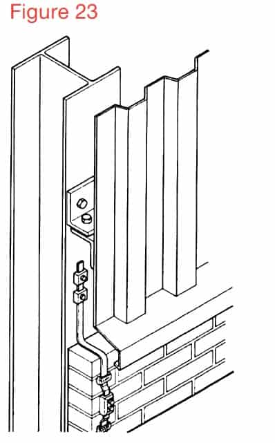
If the metallic parapet is to be used as part of the air-termination network it has to be both electrically and mechanically continuous, the minimum thickness should comply with the dimensions in Table 1 and Figure 23.
Table 1
Material for LPS Level I To IV
Prevents puncture, hot spots or ignition (minimum thickness mm (ta) requirement
Only for metal sheets where preventing puncture, hot spots or ignition is not important. Minimum thickness mm (ta) requirement
Lead
–
2.00
Stainless Steel
4
0.50
Titanium
4
0.50
Copper
5
0.50
Aluminium
7
0.65
Zinc
–
0.70
If a metallic roof parapet is not being used in the air-termination network then it should be bonded every 20 metres along the complete length and to each down-conductor (or at down conductor spacing).
Conductive metal objects above the roof surface and passing through the roof structure should be bonded onto the air termination network., examples of this could be a water tank with pipe work passing through the roof into the structure.
Example of Wallis Earth Bonds
Thorne & Derrick International
Contact us to discuss all your Substation Earthing, Cable Jointing & Terminating requirements for the installation of LV MV HV cables, copper earthing tapes and infrastructure including switchgear, transformers and electrical equipment up to 33kV.
Copper Earthing Tapes – Bare & Covered Copper Tapes
Uploaded by Chris Dodds - Thorne & Derrick Sales & Marketing Manager
Copper Earthing Tapes
Thorne & Derrick International, a leading stockist and distributor of copper earthing tapes manufactured by AN Wallis and ABB Furse provide an overview of the role and relationship of earth tapes with respect to the design of Lightning Protection Systems in accordance with British Standard BS EN 62305.
There should be at least two down conductors around the building
The down conductors should be as equally spaced as possible
Copper earth tape as down conductors should be installed at exposed corners of building
Down conductors can be fixed to any wall or surface which is non-combustible, if the surface is combustible refer to BS EN 62305 for guidance
Down conductors must not be sited in gutters or down pipes
The down conductor ideally will follow the shortest and most direct path to earth
The down conductor should as far as possible be straight and vertical
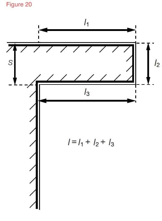
Wherever possible avoid any re-entrant loops where this is not possible the separation distance shown in Figure 22 Is required as a minimum, if this cannot be achieved another design for the down conductor system should be considered
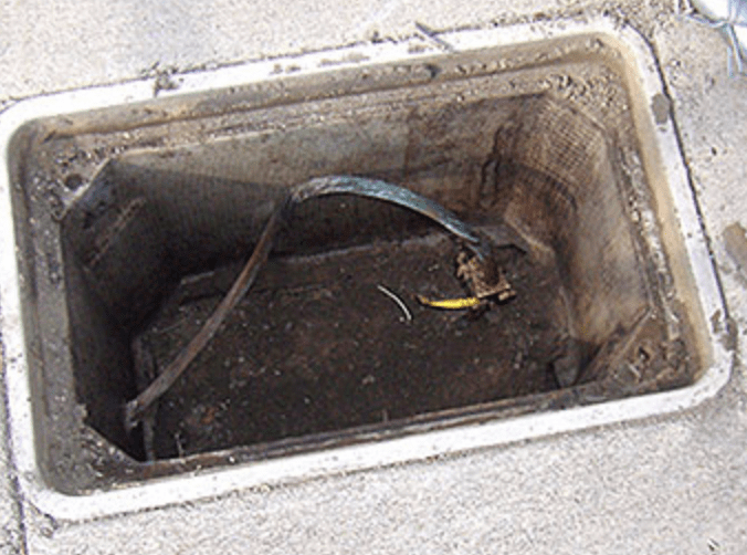
A test joint should be fitted on each down conductor to enable disconnection from the earth network and provide access for earth resistance measurement and maintenance
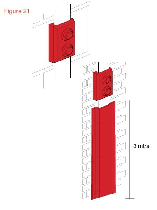
The bottom 3 metres of the down conductor should be protected within a metal guard or PVC covering at least 3mm thick to deter vandalism and copper earthing tapes theft Figure 21. The test clamp should be fixed above the capping wherever possible Figure 21.
Down Conductor should be protected by metal guard of PVC covering at least 3mm thick to deter vandalism
If the air termination is a metal rod on a non conductive mast, at least one down conductor is needed for each mast.
No additional down conductors are required for masts made of metal or interconnected reinforcing steel.
If the air termination consists of one or more catenary wires at least one down conductor is needed at each supporting structure.
Positioning the down conductors
There should be multiple down conductors following the shortest possible path to earth via the conductive copper EARTH tapes.
Typical values of the distance between down conductors, subject to architectural and practical constraints are given in the table below.
Table 5.4 – Typical down conductor spacing’s and distance between ring conductors
Class of LPS
Typical Ring Distances (M)
I
10
II
10
III
15
IV
20
It may not be practically possible to space the down conductors exactly as required, so the spacing’s can be adjusted by ±20% but the average spacing of all down conductors must conform to the typical distances for the class of LPS.
If it is not possible to place down conductors at a side or part side of the building the down conductors that should be on that side should be placed as additional down conductors compensating for the other sides. The distance between the installed down conductors should not be less than one-third of the required down-conductor distances dependent upon the class of LPS.
Equipotential bonding to conducting parts of the structure should be performed according to BS EN 62305-3, 6.2.
The distance between the down-conductor and the internal services must satisfy the distance requirements covered in the table above.
If the separation distance required to avoid dangerous sparking between the down conductor and the internal services cannot be satisfied, the number of down conductors should be increased until the required separation distance is met.
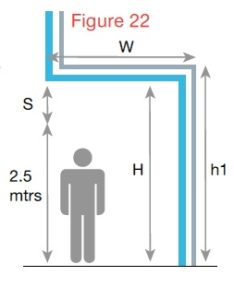
Protection on a Cantilevered Structure
There is a risk when the down conductor goes into a cantilever that a strike could flash over to this risk the separation distance, h in metres, should satisfy the the person standing underneath 2.5 as shown in figure 22. To reduce mtrs following conditions.
H > 2.5 + S
S – Is the separation distance in metres calculated.
2.5 – represents the height of a typical person with their hand in the air.
Using natural components as down conductors
The natural components can be used as down conductors provided the components comply with the requirements of BS EN 62305.
The natural components can be used provided there is electrical continuity, where the joints are tightly bolted they can be considered as electrically continuous Figure 23.
Natural components as down conductors
The facade elements, profile rails and metallic sub-constructions of facades can be used provided their dimensions conform to the requirements for down conductors and metal sheets or metal pipes, not less than 0.5mm thick.
If the metal façade of the building is to be used as the down conductor then BS 62305 offers specific guidance.
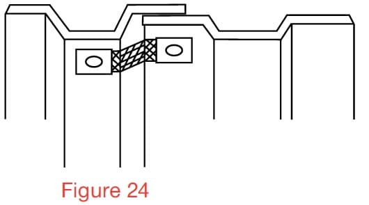
Each overlapping vertical joint at each down-conductor position should be bridged by flexible metal strapping. See Figure 24.
Overlapping vertical joint bridged by flexible metal strapping
Connections between the sheet metal panels should have a minimum contact surface area of 50 sqmm and be capable of be capable of withstanding the mechanical forces of a lightning discharge.
If access to the rear of the façade is not possible and the only type of fixing available for connections between facade sheets and the air termination or down-conductor tapes is pop rivets then these should be at least four 5mm diameter rivets and used on a length of conductor, such as copper earth tape, a minimum of 20mm long. (C.S.A or conductor (connection component) min 50 sqmm).
Down conductors not using the
natural components of the building
Where down conductors are installed on the building not using the natural components then consideration needs to be given to the separation distance between the internal columns and internal partition walls with conductive parts.
If these conductive columns and partitions do not satisfy the separation distance conditions they must be connected to the air termination system at roof level and to the earthing network at ground level.
What Is BS EN 62305-3:2011?
Part 3 of EN 62305 sets out all the requirements needed to protect buildings and structures against physical damage by implementing a lighting protection system (LPS). It also looks at how to protect humans and animals (living beings) against injury if they are close to an LPS. By defining these safety measures, this standard helps you to minimise damage, invest in the right electrical protection equipment and maximise hazard prevention in buildings.
Thorne & Derrick International
Contact us to discuss all your Substation Earthing, Cable Jointing & Terminating requirements for the installation of LV MV HV cables, copper earthing tapes and infrastructure including switchgear, transformers and electrical equipment up to 33kV.
Earth Bars – manufactured from 50x6mm Tinned Hard Drawn Copper Bar
Uploaded by Chris Dodds - Thorne & Derrick Sales & Marketing Manager
Earth Bars
Advantages & Applications Of Tinned Copper
The following article has been written to provide some basic advice and reasoning for the specification of Tinned v Standard Copper Earth Bars when designing earthing systems for LV MV HV building services and substation protection exposed to wet conditions during normal operation.
Copper is used in the manufacture of Earthing & Lightning Protection Systems due to the high thermal and electrical conductivity, ease of manufacture, high recyclability and good corrosion resistance of the material. Copper, a noble metal that occurs naturally in its elemental form, is almost totally impervious to corrosion from soils found worldwide.
But it would be misleading to infer that copper will not corrode.
Tinned copper is a type of copper coated with a thin layer of tin used to provide protection to earth bars against the tarnishing and corrosive effects of oxidisation, commonly referred to as rusting.
The thin layer of tin effectively shields the copper surface of the earth bar inhibiting oxidisation – preventing air from reacting with the copper in the presence of atmospheric moistures. Put simply – no air, no oxide, no corrosion.
The copper tinning process provides enhanced protection against climatic variations and atmospheric conditions without significant reduction in the functionality and electrical conductivity of the copper metal.
Oxidised copper surfaces display poor conductivity compared to clean and smooth tinned copper which prolongs the service life of the earth bar at comparatively low added-on cost.
Tinned copper is higher cost than non-tinned copper but provides extended service life and field performance compared to standard bare type copper especially in wet condition installations.
These types of earth bars are commonly specified and installed in outdoor locations in the water utility, marine and offshore industries where high levels of atmospheric corrosion caused by environmental factors and moisture levels such as rain, fog and condensation necessitate improved levels of corrosion protection. Outdoor air can act as an electrolyte because it contains a variety of components which can cause corrosion of any metal.
Tinned copper handles wet conditions, high temperatures and humidity to maintain the conductive integrity of the earth bar for electrical engineering applications.
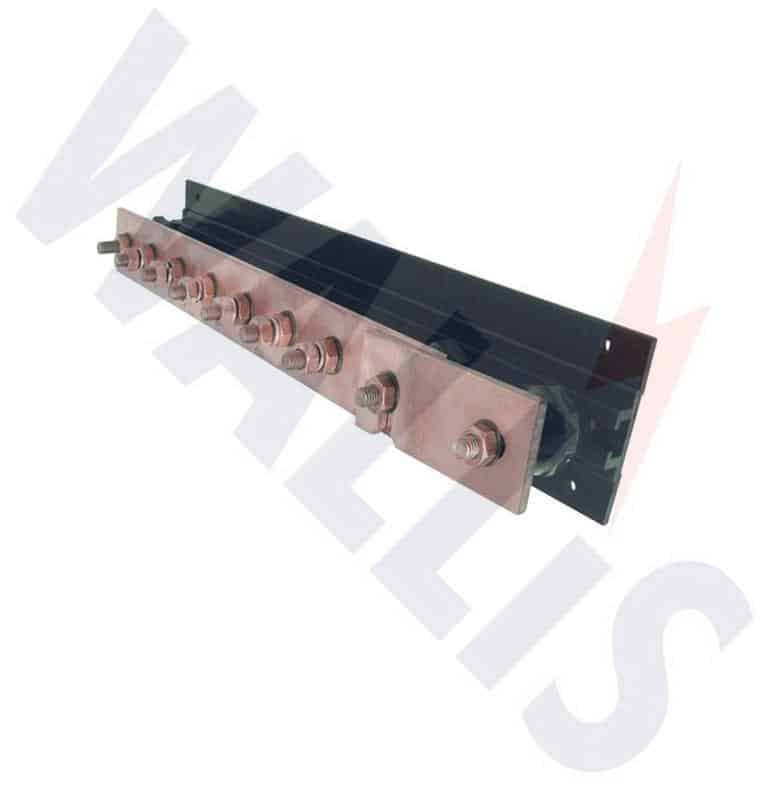
AN Wallis manufacture both standard copper and tinned copper earth bars from 6 way up to 30 way on short lead times in standard, single link or twin-disconnection link design. Image: Wallis 6 Way Earth Bar.
Applications & Necessity Of Tinned Earth Bars
Earth bars are used to provide a convenient common earthing point for electrical installations requiring an Earthing & Lightning Protection System – copper earth bars are available with single or twin disconnecting links which means the earthing bars can be isolated for electrical testing.
Tinned copper earth bars could be used in external applications or where atmospheric conditions are more severe than normal i.e. high humidity or moisture content areas and marine and offshore saline atmospheres.
Tinning protects the copper and protects the earth bars from the formation of copper oxide, tin effectively prevents oxidation.
Earth bars are a standard, efficient and convenient way of providing a common earth point with integral disconnection links permitting safe electrical isolation for testing purposes in the switchroom.
Why Should Earth Bars Be Tinned?
Tin is a soft white metal which can easily be polished, scratch brushed or flow melted to provide a bright finish.
Tin is non-toxic and is not greatly affected by the organic acids. Sulphur compounds do not readily tarnish tin and it is not impaired by either air or water but reacts with hydrochloric acid to form stannous chloride.
Tin is one of the less susceptible metals to corrosion attack consequently tin-plated surfaces of copper earth bars are adequately protected against atmospheric corrosion and hence provides longer life when exposed to corrosive atmosphere installations.
In normal state unaffected by corrosion copper is a rich brown colour – pictured below is an instance of copper oxide (“greening”) showing advanced corrosion to underground earth tapes. Tinning of the earth tapes and copper conductors prevents “greening” of the copper surface – furthermore this copper run-off can be very corrosive to galvanised steel support structures on medium/high voltage substations.
Benefits of a Tinned Earth Bar
Tinning a copper bar protects against atmospheric corrosion providing longer life when exposed to corrosive atmospheres
Tinning protects the earth bar against the formation of copper oxide (oxidisation)
Tinned earth bars are an excellent solution to extend longevity and have reasonably low resistance
Used in external/outdoors applications or where atmospheric conditions are more severe and aggressive than normal i.e. high moisture content areas, high humidity in both onshore (eg water treatment works) or offshore (oil/gas platforms)
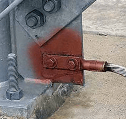
Pictured:Here a tinned AWG 4/0 stranded copper conductor is bolted to a galvanised steel flange of a support column on a high voltage substation. Note the high pressure compression fitting installed using hydraulic crimping tools and protective paint for added protection of the copper cable lugs and conductor against corrosion in above-ground outdoor applications.
➡ T&D together with Wallis can offer a bespoke design service for custom earth bars in both tinned and standard copper construction – sizing, number of cable terminations, fixing materials and bases can be tailored to comply with specific site requirements and drawings are available on request to ensure the earthing bars are suitable.
Earth Bars
The following range of Earth Bars without disconnection links are available in both standard copper and tinned copper versions:
AN Wallis Part Number
Number of Ways/Terminations
Earth Bar Dimensions (length x width x height)
Unit Weight
EBC006
6
400mm x 90mm x 60mm
2.00kg
EBC008
8
500mm x 90mm x 60mm
2.30kg
EBC010
10
650mm x 90mm x 60mm
3.20kg
EBC012
12
750mm x 90mm x 60mm
4.00kg
EBC014
14
850mm x 90mm x 60mm
4.90kg
EBC016
16
950mm x 90mm x 60mm
5.80kg
EBC018
18
1100mm x 90mm x 60mm
6.70kg
EBC020
20
1250mm x 90mm x 60mm
7.60kg
EBC024
24
1400mm x 90mm x 60mm
8.50kg
EBC026
26
1550mm x 90mm x 60mm
10.30kg
EBC028
28
1650mm x 90mm x 60mm
11.20kg
EBC030
30
1800mm x 90mm x 60mm
12.10kg
Earth Bars With Single Disconnection Link
The following range of Earth Bars with single disconnection links are available in both standard copper and tinned copper versions:
AN Wallis Part Number
Number of Ways/Terminations
Earth Bar Dimensions (length x width x height)
Unit weight
EBC106
6
485mm x 90mm x 60mm
2.50kg
EBC108
8
585mm x 90mm x 60mm
3.00kg
EBC110
10
735mm x 90mm x 60mm
3.90kg
EBC112
12
835mm x 90mm x 60mm
4.70kg
EBC114
14
935mm x 90mm x 60mm
5.60kg
EBC116
16
1035mm x 90mm x 60mm
6.50kg
EBC118
18
1185mm x 90mm x 60mm
7.40kg
EBC120
20
1335mm x 90mm x 60mm
8.30kg
EBC122
22
1385mm x 90mm x 60mm
9.20kg
EBC124
24
1485mm x 90mm x 60mm
10.10kg
EBC126
26
1635mm x 90mm x 60mm
11.00kg
EBC128
28
1735mm x 90mm x 60mm
11.90kg
EBC130
30
1885mm x 90mm x 60mm
12.80kg
Earth Bars With Twin Disconnection Links
The following range of Earth Bars with twin disconnection links are available in both standard copper and tinned copper versions:
AN Wallis Part Number
Number of Ways/Terminations
Earth Bar Dimensions (length x width x height)
Unit Weight
EBC206
6
570mm x 90mm x 60mm
3.10kg
EBC208
8
670mm x 90mm x 60mm
3.70kg
EBC210
10
820mm x 90mm x 60mm
4.50kg
EBC212
12
920mm x 90mm x 60mm
5.30kg
EBC214
14
1020mm x 90mm x 60mm
6.20kg
EBC216
16
1120mm x 90mm x 60mm
7.10kg
EBC218
18
1270mm x 90mm x 60mm
8.00kg
EBC220
20
1420mm x 90mm x 60mm
8.90kg
EBC222
22
1470mm x 90mm x 60mm
9.80kg
EBC224
24
1570mm x 90mm x 60mm
10.70kg
EBC226
26
1720mm x 90mm x 60mm
11.60kg
EBC228
28
1820mm x 90mm x 60mm
12.50kg
EBC230
30
1885mm x 90mm x 60mm
13.40kg
Temper Designation Standard
Tensile Strength (Ksi)
Min
Max
Yield Strength (Ksi) Min
060 Soft
30
38
…
H00 Cold-Rolled 1/8 Hard
32
40
20
H01 Cold-Rolled, high yield 1/4 Hard
34
42
28
H02 Half Hard
37
46
30
H03 Three quarter Hard
41
50
32
H04
43
52
35
Tin Plating Services For The Electrical & Electronics Industry
The following comments have been kindly provided by Ian Molyneaux of Karas Plating Ltd – the UK’s most respected metal finishing company.
Bright Tin Plating
Tin is a silvery malleable metal that doesn’t get easily oxidized in air and is used to coat other metals to prevent corrosion. The electrical and electronics industry are heavily dependent on tin and tin alloy coatings for solderability most of which is done by electroplating. Tin plated metal is also used for food packaging giving the name to tin cans which are made mostly of steel.
Tin plating is used extensively in the electrical engineering industry to provide protection and to confer solderability. Tin electroplating is also widely used in manufacturing printed circuit boards (PCBs) and electronic components. Most electronic circuit components are made by soldering therefore the surfaces of the conductors being connected are coated in tin or a tin alloy aiding solderability. Additionally tin coating protects the components and connection from corrosion in aggressive atmospheres.
Tin is one of the easiest metals to electro deposit and one of the advantages of electroplating is that no limitation is imposed on the thickness of tin that can be applied. The required thickness can be attained by adjusting the bath parameters and time.
Tin is usually plated with a bright or matt finish. Bright tin is obtained from electroplating solutions containing brighteners, ie. organic additives causing formation of very fine grains of deposit. It has excellent cosmetic appearance.
Matt tin coatings are made in electrolytes with few grain refiners, but without brighteners. It has a dull appearance but the level of internal stresses in matt tin deposits are much less than in that of bright tin.
Bright Tin Plating
Dull Tin Plating
What is the difference between pure tin, bright tin, and matt tin?
Matt tin coatings are made in electrolytes without the addition of brighteners. Matt tin has a dull appearance, but the level of internal stresses in matt tin depositions is much lower than it is in bright tin depositions. Matt tin (in contrast to bright tin) is characterised by low whiskers growing, therefore, it is used in electronics.
Characteristics:
a dull, semi-bright or satin-bright appearance
disperse reflectivity
existence of grains with an average size in the range of a few microns
the deposit is free of the co-deposited brighteners found in bright tin plating
Dull tin is ideal for electronic or precision components. Deposits give good solder ability even after heat or steam ageing.
Karas Plating can plate onto substrates of aluminium, copper and copper clad aluminium busbars in both bright and dull tin.
Aluminium and copper clad aluminium busbar are generally used for reduction in weight and cost but both are easily tin plated
Earthing and lightning protection manufactured by AN Wallis from high conductivity copper to BS EN 13601 is installed to protect buildings, overhead lines and medium/high voltage substations (MV-HV) against potentially catastrophic damage that can be caused by a lightning strike resulting in short circuiting of power networks.
The Wallis product range includes copper earth rods (solid copper, copper bond and stainless steel types), earth bars, earth tapes, earth clamps and aluminium tapes.
As the leading UK manufacturer of specialist Earthing and Lightning Protection Products, Wallis aims to provide the highest quality products without compromising on price or product performance in a safety critical application.
Quality assurance is integral to Wallis and to ensure this practice continues all earthing and lightning products are manufactured to stringent British and international standards.
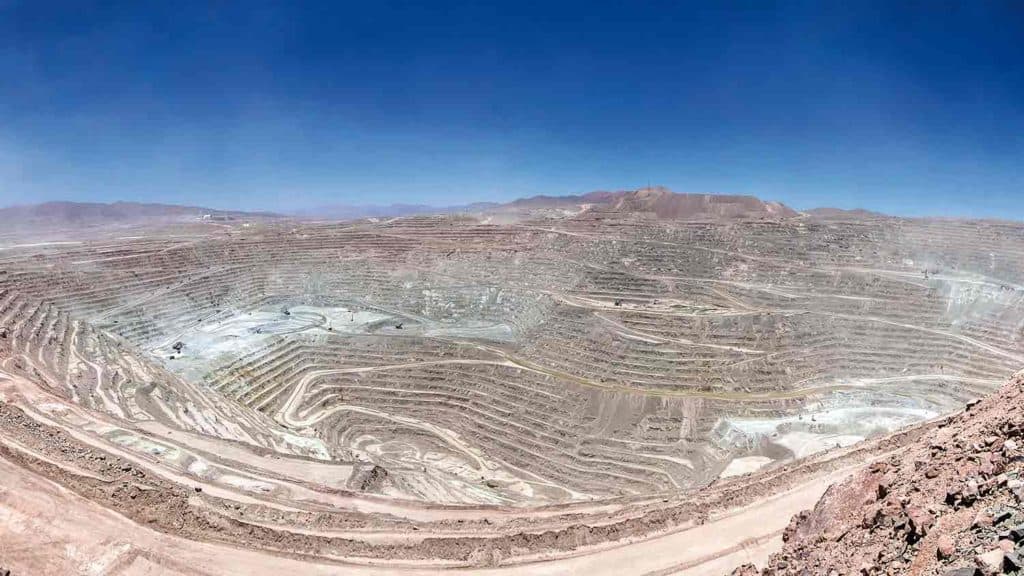
Did You Know?
The Escondida copper mine in the Atacama Desert in Northern Chile is currently the world’s largest copper mine by reserve. The copper mine contained more than 32 million tonnes (Mt) of recoverable copper reserves at the end of 2012.
THORNE & DERRICK are national distributors of LV, MV & HV Cable Installation, Jointing, Duct Sealing, Earthing & Electrical Equipment – we service UK and global businesses involved in cable installations, substation, overhead line and the installation of medium/high voltage cable joints and terminations at LV, 11kV, 33kV and HV.
Contact us for 3M Electrical, ABB, Alroc, AN Wallis, CATU Electrical, Cembre, Centriforce, CMP, CSD, Elastimold, Ellis Patents, Emtelle, Euromold, Filoform , Furse, Lucy Electric & Zodion, Nexans, Pfisterer, Polypipe, Prysmian, Roxtec, Sicame, WT Henley.
uploaded by Chris Dodds - Thorne & Derrick Sales & Marketing Manager
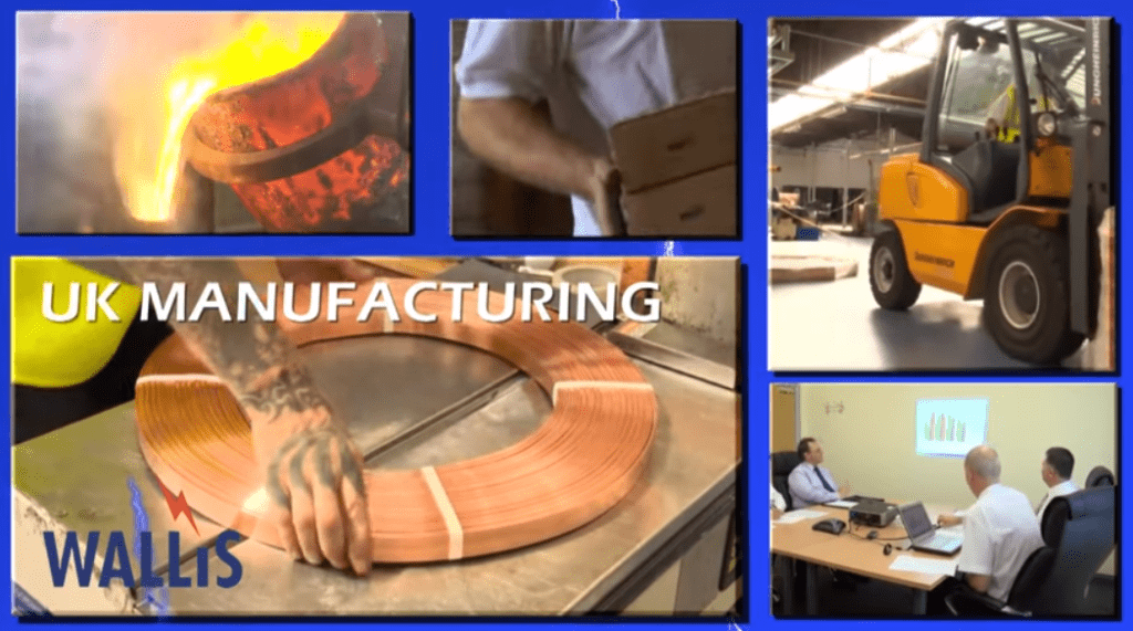
Thorne & Derrick, are UK distributors, stockists and suppliers for AN Wallis Copper Earthing & Lightning Protection Systems – we were recently invited to visit their UK based location in Nottingham to understand and learn more about the manufacturing processes for copper earth tapes.
In this post we provide a selection of photographs taken during the AN Wallis factory tour – all copper earthing products are manufactured according to BSI ISO 9001:2008 and BSI OHSAS 18001:2007.
Since 1946 AN Wallis earthing products including earth tapes, earth rods, earth bars and earth mats manufactured from high conductivity copper have provided Earthing & Lightning Protection to LV MV HV Network Assets including primary/secondary substations, overhead line towers and power cable systems from 11kV/33kV up to 400kV.
Copper is a chemical element with symbol Cu (from Latin: cuprum) and atomic number 29 – a soft, malleable, and ductile metal with very high thermal and electrical conductivity. A freshly exposed surface of pure copper has a reddish-orange colour.
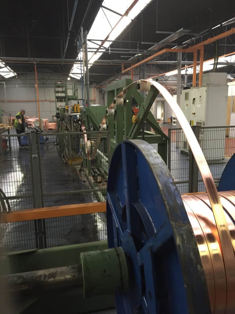
Earth Tape
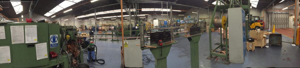
A panoramic photograph of the AN Wallis production facility and factory where the earth tapes are manufactured from raw material into finished product – earthing tapes in bare copper form or with optional PVC covering and coloured are manufactured in a range of tape thicknesses and widths to achieve the required cross sectional area.
AN Wallis extensive copper feed stocks enable fast turnaround of major earthing project requirements for the global electrical power and utility industry – the 17,000 square feet manufacturing facility and extensive raw material copper holding ensures short lead times with “off the shelf” deliveries or quick turnaround manufacturing of all earth tapes.
1 Earth Tape Manufacturing
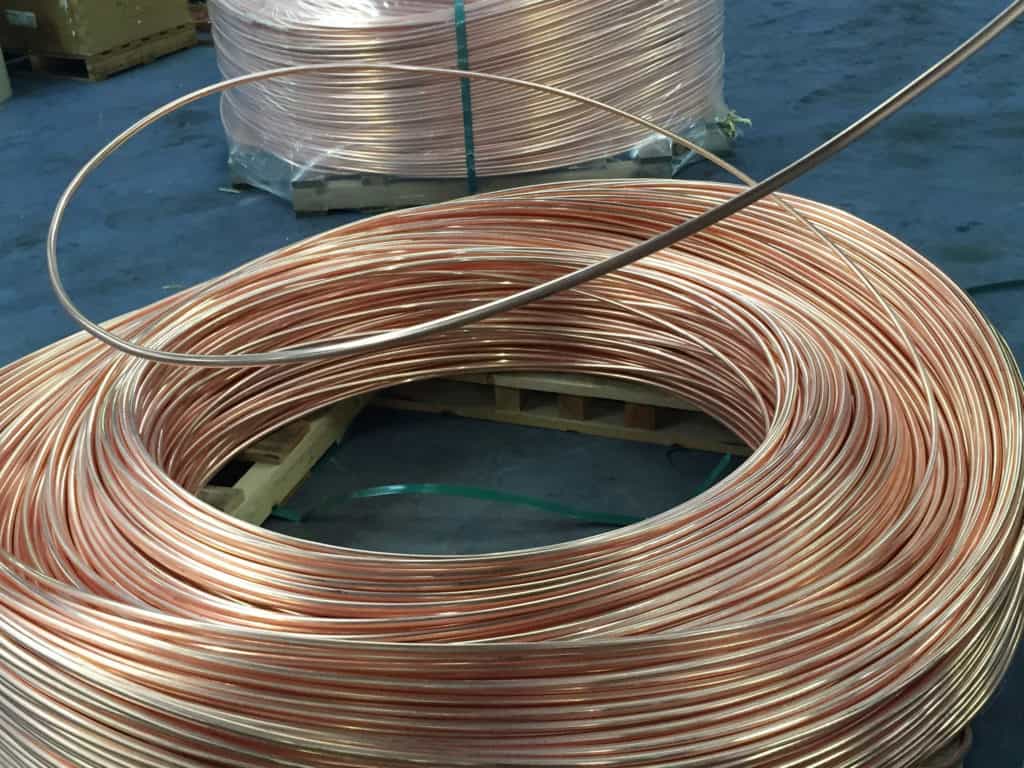
2 Raw Material Copper Feed Stocks
The raw material is supplied in solid copper conductor form – note the circular form of the feed stock which must be processed via the manufacturing machinery into the flat tape copper configuration. The Conform machine processes the copper into flat tape form and can be pre-set to optional dimensions. Weekly maintenance checks of the Conform machine include a general clean down, gearbox oil level check, hub cooling oil check, hub cooling water check and ensuring no water or hydraulic pipes are leaking.
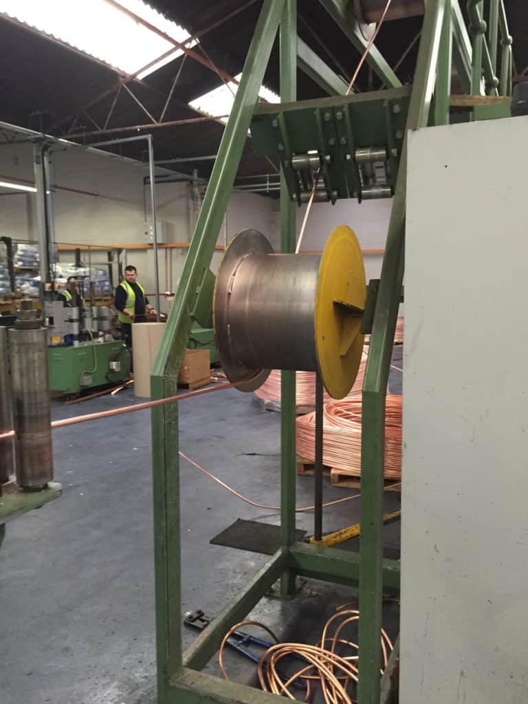
3 Copper Earth Tapes
The circular copper conductor is fed from coil into the Conform machine – the conductor is conformed from circular to flat configuration producing a range of flat copper earth tapes from 12.5mm to 50mm widths. Computer software, such as CDEGS, can be used to calculate the power system earthing and grounding. Asset managers must calculate the level of site protection required depending on the cross section area of conductor required to provide effective earthing and lightning protection.
Methods to improve high voltage substation earthing and grounding with supporting measurements of earth resistance and computational models to simulate the possible Ground Potential Rise (GPR) due to injected current surges are a key consideration in providing effective lightning and earthing protection.
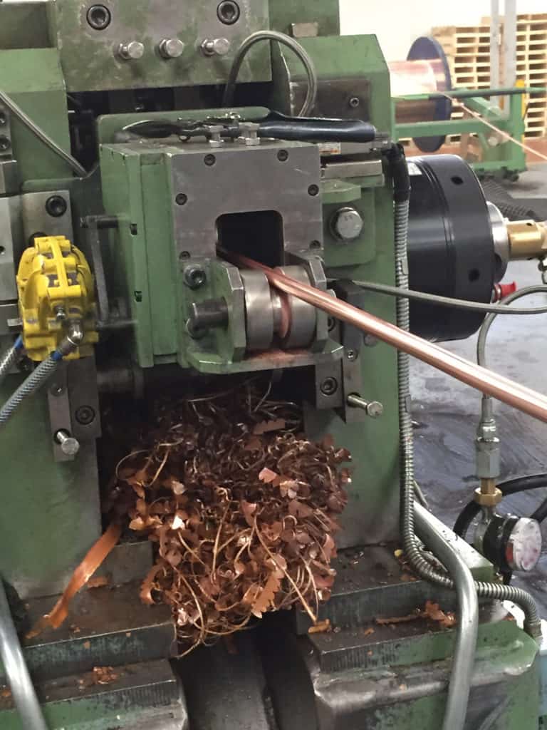
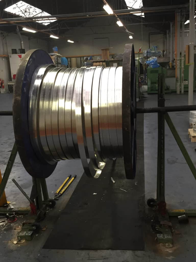
4 Processing Circular Form Copper Into Flat Earth Tape
Here the circular copper conductor is shown entering the Conform machine – in the “On” mode the motors and pumps feed the copper conductor into the Conformer via the machine wheel. Adjustable settings enable the manufacture of an extensive range of widths and thicknesses of copper tape.
5 Copper Earth Tapes
From this angle the photograph shows the complete AN Wallis manufacturing process for copper earth tape. The finished copper earth tape has now been conformed by machine to a flat tape design from the circular copper feed stock – this production run is manufacturing 50mm wide x 6mm thick copper earth tape, a UK utility standard for medium/high voltage substation earthing. The copper earth tape is annealed and produced with radiused edges for safe site handling by installers.
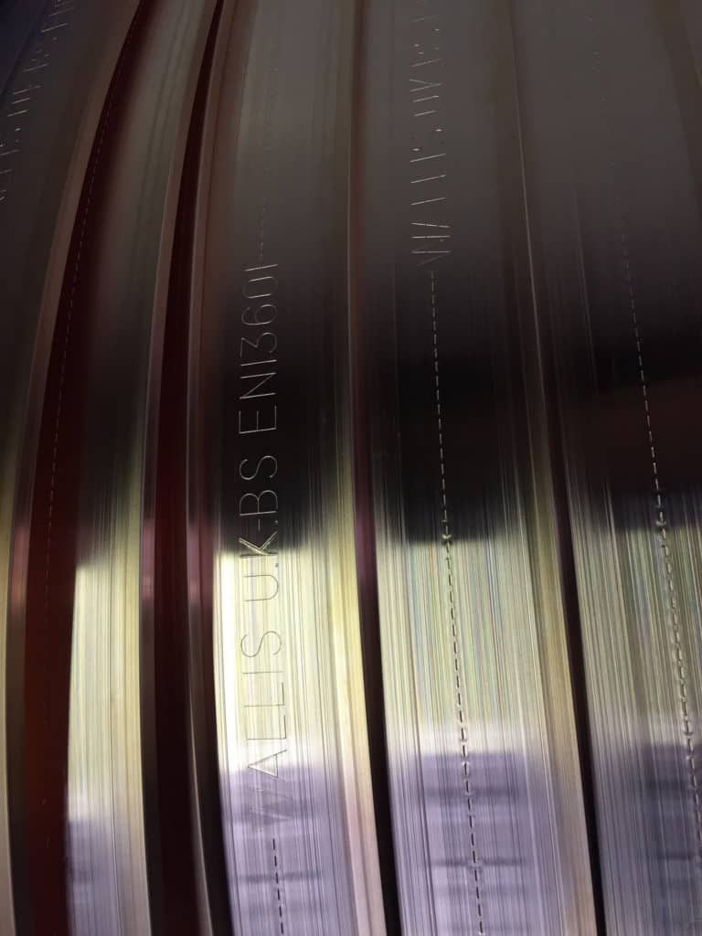
Wallis copper tapes are marked “Wallis U.K.- BS EN 13601”.
BS EN 13601 2013 is the current British standard covering Copper, Copper Alloys, Copper Rod, Bar & Wire for electrical purposes. The copper tapes are available embossed or inscribed with the client owners name as a copper theft deterrence measure.
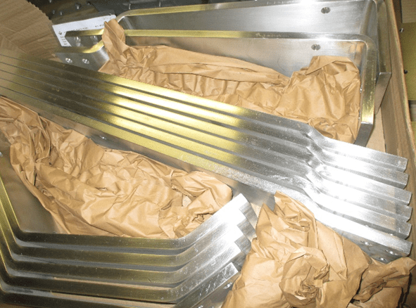
6 Aluminium Earth Tapes
AN Wallis manufacture aluminium earth tape also at their Nottingham factory – lower cost than copper but with reduced conductivity the range of aluminium earth tapes are also available from stock.
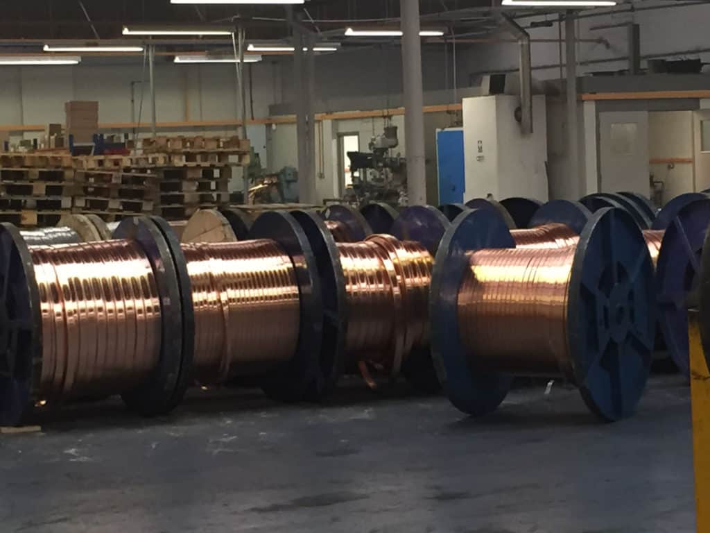
7 Large UK Stocks Of Copper Earth Tapes
AN Wallis manufacture and hold the largest UK stocks of copper earth tapes – T&D, the UK’s largest supplier of AN Wallis products provide internationally competitive prices, delivery and technical support. A complete supporting range of copper clamps are available to secure and install the earth tapes to building infrastructures.
Full range of Earth Tapes
About AN Wallis
AN Wallis & Co Ltd has over 70 years experience in the design and manufacture of Lightning Protection, Earthing & Low Voltage Electronic Surge Protection products – a broad range of technical and earthing design services are provided including full design of structural lightning protection systems, design of substation earthing systems, soil resistivity tests, commissioning and project consultation.
AN Wallis has grown steadily and is a recognised world leader in the manufacture of quality Earthing, Lightning Protection, LV Surge Protection and Exothermic Welding products.
The Earthing Product range includes copper tape conductors, earth bars, copper earth plates, DC fixings clips, earth rods produced from solid copper, copper bond and stainless steel. Air terminals, earth rod clamps, inspection pits concrete and heavy duty polymer, earth rod seals, low resistance soil conditioning agents and also CU-NNECT exothermic welding products.
Thorne & Derrick distribute the complete range of Copper Earthing Products manufactured by AN Wallis to UK and overseas projects and competitive prices from extensive stocks – this includes earthing products for MV HV EHV substation projects including:
Neasdon Depot Substation London Underground / Enterprise Rail
Swansea 400kV Substation National Grid / Electricity Alliance West
Cardiff East 400kV Substation National Grid / Electricity Alliance West
Sundon 400kV Substation National Grid / Electricity Alliance West
The products also provide Earthing & Lightning Protection for railway traction substations, distribution substations, overhead line towers, solar farms, STOR sites, data centres, hospitals and hazardous area sites.
THORNE & DERRICK are national distributors of LV, MV & HV Cable Installation, Jointing, Duct Sealing, Earthing & Electrical Equipment – we service UK and global businesses involved in cable installations, cable jointing, substation, overhead line and electrical construction at LV, 11kV, 33kV and EHV.
Contact us for 3M Electrical, ABB, Alroc, AN Wallis, CATU Electrical, Cembre, Centriforce, CMP, CSD, Elastimold, Ellis Patents, Emtelle, Euromold, Filoform , Furse, Lucy Electric & Zodion, Nexans, Pfisterer, Polypipe, Prysmian, Roxtec, Sicame, WT Henley.
uploaded by Chris Dodds - Thorne & Derrick Sales & Marketing Manager
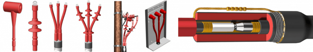
Although modern cable manufacturing technologies evolve and develop the essential factors to consider when installing heat shrink type joints or terminations on medium/high voltage power cable systems remain essentially unchanged. Materials quality allied with installation by competent trained Jointers is the fundamental basis to ensure reliability, safety and operational service of MV HV cables, joints and terminations.
Here, from the archive we reproduce an important Technical Article by Norman Poulter – Norman was the Managing Director of Shrink Polymer Systems, the UK’s leading specialist manufacturer and assembler of MV HV cable joints and terminations for standard and non-standard cable applications up to 33kV.
Today, SPS’s Managing Director Richard Poulter continues to support the UK and overseas market with the competitive supply of MV HV heat shrink cable accessories for all cable voltages including 11kV/33kV and types such as XLPE, EPR, PILC and Triplex cables.
Medium & High Voltage Cable Accessories
author Norman Poulter
Power cable installation throughout Europe and the UK until the early 1960s exclusively used impregnated paper for the primary insulation of the conductors for both single- and three-core MV-HV cables.
The UK adopted both aluminium and lead-sheathed cables with and without steel wire armouring (SWA); these are still in use today. In the very early days of paper-insulated cable terminations, dry-type systems were employed along with compound-filled end box designs and cast-iron boxes with hot pour bitumen for cable joints.
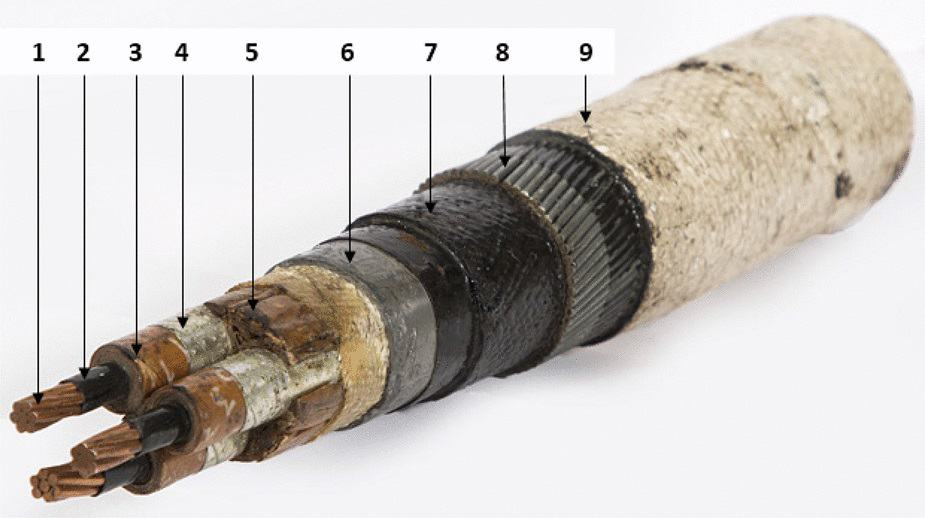
PILC SWA Paper-insulated Lead Covered & Steel Wire Armoured Cable
Circular stranded copper phase conductors
Conductive paper screen
MIND paper insulation
Metallised paper insulation screen
Circularising fillers
Lead sheath
Bitumenised hessian bedding
Galvanised steel wire armour
Bitumenised hessian serving with whitewash coating
11kV PILC Cable
Cold shrink products such as push-on, pre-stretched tube and grease applied slip-on types also became popular in the 1960s and are still specified by specific electric authorities and utilities for terminating and jointing MV-HV cables.
In the early 1970s polymeric (XLPE) cable types began to emerge in Europe and the UK, mainly on three-core cables, while the USA employed the single-core cable concept at 10kV, 20kV and 35kV medium voltages.
The heat shrink concept began to be employed at this period by the utility companies and has now spread internationally as the preferred method of cable terminating and jointing.
There are many advantages of using heat shrink cable accessories and techniques, such as:
Wide shrink ratio – one joint/termination kit assembly to cover numerous cable ranges
Heat concept dries out moisture from the MV HV cables
Mastic seals are activated by heat so sealants are usually visible at sleeve ends
They are not size sensitive and can be used on sector-shaped conductors
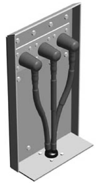
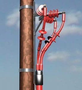
Figure 1 – Cable Box Air Insulated Termination
Cable Joint & Termination Kit Instructions
Shrink Polymer Systems also realised the importance of good cable jointing and terminating instructions. By using pictorial drawings with a minimum of text, non-English speaking countries can identify the important highlighted areas in an easily identified format.
Failures are nearly always attributed to poor cable preparation by the jointer and failure to observe the correct jointing procedures in the areas where the electric cable stresses are prudent, such as the semicon screen cut back.
Although the USA shares a language with the UK, there are many differences in the selection of words to describe various things. Below is a list of some UK terminology and the common equivalent used in the United States.
Core – Conductor
Screen – Shield
Joints Jointing – Splice Splicing
Cable Jointers – Cable Splicers
Earth Earthing – Ground Grounding
Armour Support – Reinforcing
Metal Sheaths – Armour
Self-Amalgamating – Self-Fusing
Heat Shrink Cable Joints
& Cable Terminations
Terminations
Terminations | Indoor or Outdoor
The major MV HV switchgear and transformer manufacturers have, for many years, designed dry-air filled cable boxes, resulting in a much greater demand for heat shrink-on terminations.
All heat shrink cable terminations and joints have to be tested to various international standards, and while cables prepared by experts in perfect laboratory conditions will undoubtedly meet these requirements under test, field experience shows that failures still occur at working voltage due to a variety of reasons.
Typical List Of Weakness Resulting In Failures
Of Heat Shrink Terminations
Compression lugs, or crimp lugs, fitted to outdoor terminations of the compression tube type with inspection holes allowing moisture to penetrate the conductor cores.
Failure to eliminate air pockets on paper-insulated, lead covered (PILC) three-core “belted” cables in the crotch area.
Core crossing resulting in discharge if cores are too close to each other in an unscreened area at the core cross point. This results in the air “breaking down” electrically at approximately 4kV on an 11kV cable, 6kV on a 24kV cable and 9kV on 36kV cable. The anti-track heat shrink material then begins to erode due to the ionisation of the air, which over time will inevitably cause failure of the cable termination.
Poor cable preparation, in particular on extruded dielectric types where insufficient care is taken on semiconductive screen removal at the crucial area of the screen cut-off. Cable jointers are generally reluctant to purchase engineered screen removal tools and rely on knives, blades and homemade tools for removal. This can result in cutting through the screen and into the primary insulation, leaving voids which result in the discharge phenomena described in the third item above. Even well-prepared screen removal at the cut-off point can result in a possible void, as the stress control tube may not follow the semi-conductive edge profile. (See figure 2.)
Moisture penetration due to poor heat shrink and mastic sealing techniques.
Inadequate phase-to-phase and phase-to-earth clearance.
Tracking.
Poor cable jointing instructions.
Figure 2
There are solutions and remedies to these weaknesses relating to MV HV cable accessories which will be described later in the article.
Joints
Many of the points discussed regarding cable terminations are also relevant to joints.
The object of the cable jointing exercise is to replace all the materials that were removed to joint the conductors and replace them in such a way as to replicate the cable as closely as possible to its original state.
There are many techniques used in conductor jointing from “sweating” the weak-back ferrule (normally associated with the original cast iron paper joints) to compression and the present popular “shear bolt” designs.
Connector jointing is a complex subject due to the variety of designs for copper and aluminium conductors in circular-solid, circular-stranded, and sector-shaped styles.
There is also the consideration of copper being jointed to aluminium, cables of unequal cross sectional area being jointed to themselves, and transition jointing where paper is being jointed to polymeric at medium or high voltages.
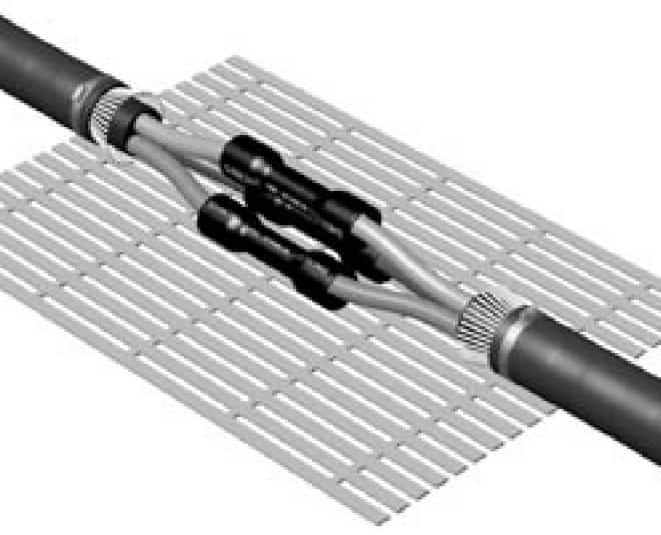
Figure 3 An 11kV 3 Core Heat Shrink Cable Joint
Let’s look at some of these designs.
Compression Connections – Crimps
There are a substantial number of manufacturers, such as Cembre, who specify suitability of their electrical connector design for voltages up to 33kV/36kV. Caution is needed if the body of the barrel is not smooth and does not have tapered ends.
Also, responsible MV HV connector manufacturers will be able to manufacture appropriate crimping tooling for their designs or confirm the compatibility of other cable tooling and die combination for their connectors. There are three types of crimping configurations currently in use: hexagonal, oval, and indent.
For instance, the Cembre HT131-C is the industry standard hydraulic crimping tool used by LV HV cable jointers to install copper type lugs and splices onto stranded cable conductors.
Oval and hexagonal crimping can leave sharp “ears” if incompatible tooling is used.
These “ears” must be filed smooth to avoid a highly stressed area which will be subjected to electrical discharge. Indent crimping will leave void holes which must be filled with high permittivity, stress relief tape.
Mechanical Connections – Shearbolts
Mechanical split type connectors are now very popular in the UK, as this design comes in two halves which are easy to apply to three-core cables at 11kV or 33kV where the cable conductors do not have to be bent. The heads shear-off at a given torque; therefore, no compression tooling or die combinations are necessary.
As this connector is “blocked,” it is also suitable for transition cable jointing for paper to plastic to stop the migration of the paper oils. There are several disadvantages of this type of connector, however. The ends of connector are non-tapered, resulting in high “step downs”, and the conductor insertion is non-centralised. (See figure 4.)
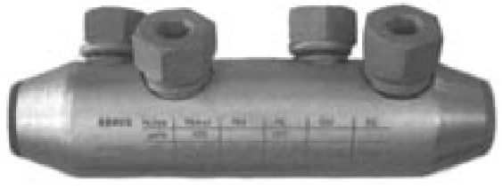
Figure 4 Mechanical Shearbolt Connector
These two conditions result in areas of high electrical stresses leading to probable discharge.
Shrink Polymer systems have now standardised on a shearbolt connector design where these critical areas of high stresses are removed by tapering the ends and centralising the conductor. (See figure 5.)
Figure 5 Mechanical Shearbolt Connector (Tapered)
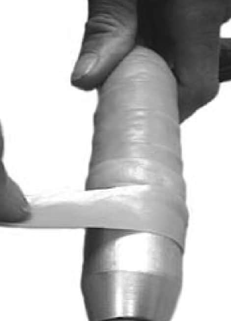
Stress-Relieving Tapes
This type of stress relief tape generally has permittivity values between 7 and 13 (test method IEC 250). (See figure 6.) This does not necessarily mean that a value of 13 will perform better than a value of 7, as void filling characteristics are equally as important.
Figure 6 MV HV Connectors & Stree Relief Tape
Shrink Polymer Systems have a yellow stress control tape, reference number TS 31785Y, which possesses high tack, high stretch, and low viscosity void-filling qualities with a permittivity value of minimum 9. Whichever type of cable connector is selected, stress-relieving tape must be used in conjunction with heat shrinkable installations.
This is applied in a half width overlap with stretch by the cable jointer and must also be applied to any indents left by the tooling.
Gaps between end of primary insulation and connector must also be filled in.
Push-on molded components are also widely used, eliminating the need to fill voids and use stress tapes.
They rely on the Faraday Cage principle, in which conductive rubber-ribbed moldings are in contact with the connector. As the potential difference across the air is very low, discharge should not occur. Push- on molded components, joints and terminations have several disadvantages however.
On three-core cables the molded components prove to be very bulky and have no design features to eliminate moisture penetration unless used in conjunction with large diameter shells and resins. On large aluminium conductor sizes the ferrule could possibly be longer than the moulded component. The positioning over the ferrule is critical.
Stress Control Heat Shrink Tubing
Shrink Polymer Systems employ the heat shrinkable, high permittivity, and low resistivity stress control tubing which is shrunk onto the stress relief tape using heat applied by a jointers gas torch previously applied.
This has the effect of achieving a more uniform distribution of the field lines. This heat shrink tube extends over the ferrule or connector and onto the prepared screen cut-off points of the medium/high voltage power cable (See figure 2.)
Insulation Thickness
When designing cable jointing systems, the thickness of the insulation over the bare conductor (i.e. ferrule) should have a safety factor in excess of 15% of the original cable.
Shrink Polymer Systems employ a one-piece, combined dual wall (insulation / semiconductive) heat shrink tube of appropriate diameter to match this insulation at voltages to 11/12kV.
At 17.5kV, 24kV and 36kV additional heat shrink insulation tubes are added to meet these cable specifications.
The cable jointer must remember to shrink this material all around the heat shrink tube to avoid inconsistent wall thicknesses on full recovery.
Typical List of Weaknesses Resulting in Failures
Incorrect crimping of connector.
Air trapped in connector (if indent crimps not filled).
Air trapped between end of insulation and end of connector.
Discharge at screen ends caused by poor stress taping / cuts to primary insulation.
Moisture ingress entering cable sheathing through poor sealing.
Inadequate insulation levels over connector.
Poor cable termination or cable joint kit instructions.
The solutions and remedies to these weaknesses are described below.
Earthing Cable Terminations
Earthing must be provided to carry any circulating currents to core screens, metal sheaths and armour wires. It must also have the ability to carry fault current. On indoor MV HV cable terminations the use of tin plated copper, solder-blocked braids, metal canisters, armour support, clamps and a complete corrosion protection system should be employed.
Figure 7 Low Voltage Heat Shrink Cable Joint For Multicore Cables
Earthing Cable Joints
Connecting the earthing components across a heat shrink cable joint requires correctly choosing and fitting the components to take care of both circulating currents and the short circuit requirements.
The outer semiconducting layer of the core/connector insulation should be wrapped in a tin copper mesh bandage and connected to the cable earth at each end.
There are a great many variations and earthing complexities and such a wide variety of cable types to consider.
Once a cable type, size, and voltage are specified it should be left to the manufacturer to supply the correct type of earthing system to meet both the national and local standards.
Remedies & Solutions To Overcome Cable Termination Failures
Always use one-piece solid lugs for outdoor termination, not squashed tube type.
Wrap butyl self-amalgamating tape around crotch and under lead cut on three-core belted cables to eliminate air. Check clearance dimensions on three-core cables.
Care must be taken in semicon screen removal not to nick the primary insulation at the screen cut-off point.
Ensure all mastic seals are in place on bushing boots, rain sheds and core tubes.
Remedies & Solutions To Overcome Cable Joint Failures
Ensure cable connector is free from “burrs,” sharp points, not squashed tube type.
Fill in all gaps with stress tapes before applying stress control tubing.
Ensure correct application of stress tape at screen cut-off points. (See figure 2.)
Fit all seals as supplied, in particular at crotch area, under armour beddings and end of connector insulations.
Cable Jointing & Terminating Instructions
It is the responsibility of cable accessory manufacturers to supply easy-to-read, simplified, pictorial jointing instructions and to avoid heavy reading of text manuals.
This point cannot be overstated, as, in the writer’s opinion, far too many jointing instructions are not read or understood, resulting in the installer compromising on the areas of importance previously mentioned. This all too often results in that first failure.
How Can We Help?
Since 1985 Thorne & Derrick have been servicing the UK and Export market with Joints, Terminations & Connectors for LV MV HV cables and power systems – call us to discuss your requirements including specialist LV cable joints for high performance applications including hazardous areas, marine and offshore cables, fire resistance cables and low smoke zero halogen cables.
klauke ekm60unv – universal cutting, crimping & punching tool The Klauke EKM 60 UNV is a versatile battery powered hydraulic universal tool engineered that can be used as a battery powered cable crimping tool and battery operated cable cutting tools that comes...
INDUSTRIAL LABEL PRINTING SOLUTIONS When clear, durable and professional identification is required across control panels, cable systems, production facilities and industrial installations, print quality, reliability and ease of use are critical. Cembre industrial label printers are designed to support...