Slingco has developed a range of products to vastly improve conductor replacement. The Catchblock, the Conductor Replacement Roller (CRR) and our range of specialist cable socks and grips.
The challenges faced by the OHL (Overhead Line) industry due to the growing number of electrical infrastructure projects built beneath existing transmission and distribution networks – alongside increasingly stringent OHL regulations – can make maintenance costly, time-consuming and challenging.
Replace OHL conductor in half the time with no need for possession orders
CatchBlock
Lightweight, robust and easy to deploy, CatchBlock helps to increase efficiency and reduce costs.
CatchBlock is an innovative overhead line (OHL) catenary roller system.
A two-rope system, allowing the replacement of old-for-new conductors. In the event of conductor failure during this process, Catchblock enables the recovery of both ends without having to lower the system.
Removes the need to erect and dismantle scaffolding, significantly reduces the risk of accidents and harm to site workers and reduces cost and project timeframe.
Designed to deploy a twin-rope system, it allows the recovery and redeployment of broken conductors without the need to take possession of road/rail or client/third party property or infrastructure.
CatchBlock Features & Benefits
Removes the need to close down essential infrastructure for conductor repairs or in the event of an emergency
Cuts down the need for scaffolding, reducing accident risk
Lightweight, robust, weatherproof and easy to deploy
Twin rope system allows for recovery and redeployment
Flexible – CatchBlock isn’t specific to a single tug design
High conductor range, including the ability to allow mid-span joints/repair sleeves to pass through safely
Blocks can be connected for use on multiple bundle conductor systems
Conductor Replacement Roller (CRR)
Provides a simple, conductor-deployed protection system using a lightweight aramid rope.
The CRR unit enables the safe exchange of conductors in three easy steps:
Laying out the pulling cable, e.g. with an electric pulling robot.
Tensioning the CRR Block assembly.
Feeding a new conductor through the cable pulleys of the CRR Block.
The rollers have a spring loaded gripping feature to secure the rope laterally without impinging any rotational movement as the rollers rotate around the axis of the conductor.
CABLE SOCKS & PULLING PRODUCTS LV MV HV
Complete range of LV, MV and HV cable pulling products for installation and enabling cable jointing in trench or ducts including LV, 11kV/33kV medium voltage (MV), 66kV/132kV high voltage (HV) and EHV transmission and distribution cables up to 400kV.
Thorne & Derrick distribute the most extensive range of Cable Installation & Electrical Distribution Equipmentto the Power Transmission & Distribution industry in the onshore and offshore wind, solar, rail, oil/gas, data centre, battery storage and utility sectors.
We service UK and international clients working on underground cables, overhead lines, substations and electrical construction at 11kV and up to and EHV transmission and distribution voltages.
Earlier this year, Thorne & Derrick welcomed Phil Day from Slingco Limited, the world-leading manufacturer of cable pulling and support socks, swivels, cable protectors, wire rope assemblies and accessories. Phil provided an Offshore Wind focussed company presentation to our Sales Team (pictured left-to-right Sarah Henderson, Carl Cox, Jonathan Hewitt, Phil Day, Jeff Jhanke, Natalie Lundie and Chris Dodds.
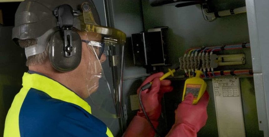
Deputy MD, Paul Hopton, outlines the additional considerations in a wind turbine environment and highlights the potential consequences of arc flash incidents.
Wind Turbines
There have been a number of arc flash incidents and accidents reported on wind turbines. The arc flash hazards are similar for wind turbines as for other types of electrical installation. There are however some other things to consider with a wind turbine application:
Wind turbines are often in remote locations, potentially making emergency response more difficult and slower e.g. offshore; on higher ground; away from centres of population
Access and egress can be difficult due to the space restrictions within the turbine as well as the height of the turbine
A fire can be started by an arc flash event, escape from any fire can be more difficult due to the access and egress difficulties
Incident energy levels can be relatively high due to the high fault levels associated with the connection of the wind farm to the extra high voltage network
Wind turbine damaged by Arc Flash
Let’s look at some of the accidents and incidents that have been reported1:
In Palm Springs, California in 2000 an operator suffered severe burns from electrical fault in a fuse holder. Hospitalised for 10 days with second- and third-degree burns.
In Byron, California in 2003 an employee was performing a manual switching operation on a pad-mounted electrical transformer. An explosion occurred during the switching operation. The employee died the following day from injuries sustained in the explosion.
In Schaller, Iowa in 2004 firemen climbed a 213 feet tower to rescue two electrical workers following a fire. Fire started following refit and testing of components.
In Norfolk, England in 2008 A worker was treated in hospital for burns caused by an electrical flash while working to repair the shore cables.
In Minnesota, USA in 2008 a man was burned while working on a wind turbine. The man sustained a severe electrical burn on his left arm.
In 2009, work was being carried out in the bottom power cabinet of a wind turbine in the United States. The individual was checking electrical connections when he came into contact with a busbar and an arc flash occurred, causing injury. The individual was hospitalised but later died of his injuries.
In Alcala, Spain in 2009 two electrical fires were reported on the same day on a wind farm.
In Pampilhosa Mountains, Portugal in 2009 one person killed and two injured in an electrical discharge. Two maintenance workers were electrocuted and badly injured after an incident with a high voltage line. The men suffered severe burns to their arms and legs.
Outland Renewable Services were issued six citations for wilful safety violations after a wind farm technician suffered severe burns from an electrical arc flash on 20th 2010, at the Iberdrola Streator Cayuga Ridge South Wind Farm near Odell. The company faced penalties of $378,000. The citations were issued for exposing maintenance technicians to electrical hazards from the unexpected energisation of transformers in three wind turbine towers. They failed to ensure that technicians working in the towers applied their own isolation devices to switch gear at ground level. The injured worker suffered third degree burns to his neck, chest and arms, and second degree burns to his face as a result of an arc flash that occurred when a transformer was unexpectedly energised by another worker.
In Nova Scotia, Canada in 2010 there was an electrical fire in a panel.
In Shangyi County, Northern China in 2011 three wind workers killed while installing and testing a wind turbine. One worker suffered an electric shock in the nacelle. The other two workers were badly injured from the resulting fire and died later in hospital.
In Nova Scotia, Canada in 2011 an electrical problem was the likely cause of a fire that completely burnt out a turbine.
In 2012, a wind turbine in Germany caught fire. The fire started in the Harmonic Filter Cabinet as a result of a loose connection in the electrical system that created an arc flash.
In 2012 a nacelle fire on a wind turbine in Spain was started by an arc flash. An employee, carrying out maintenance in the control cabinet in the nacelle, suffered burns to hands and face and was rushed to hospital in the incident.
In Co Londonderry, Northern Ireland in 2013; substantial blaze blamed on an electrical fault. Fire crews were at the site for six hours.
In Texas, USA in 2013 a wind turbine fire, fire investigators believe the turbine either had an electrical malfunction or a bearing that overheated.
Two fatalities occurred in October 2013 in the Netherlands. Two personnel carrying out routine maintenance 80 meters above the ground were trapped by a fire. The Netherlands Times reported that, because of the height, the fire department initially had trouble extinguishing the fire. The fire broke out in the afternoon but help in the form of a large crane did not come until the evening. A short circuit was deemed to be the cause of the accident, but presumably because of the fire damage it was difficult to determine the cause of the fire.
In Meinersen, Germany in 2015 a wind turbine fire. A fire in an electrical distribution box in a turbine. The fire was within the tower and was successfully extinguished after 4 hours.
In Uedem, Germany in 2016 a fire caused by electric arcing during maintenance work in the nacelle housing burned two of three technicians present. All three escaped however two technicians were injured – one badly burned. The fire completely engulfed the nacelle and burned for 3.5 hours.
In 2018 in Maine, USA fire destroyed key parts of a 9-year-old wind turbine. The turbine’s nacelle, which houses the generator and other key mechanical components was where the fire broke out. An engineer from the turbine manufacturer concluded that the turbine experienced “an arc flash,” that led to the electrical fire. The turbine maintenance was up to date however, the root cause of the arc flash remains unknown.
In Ipswich, USA in 2018 an electrical fire. The employee involved reported that he had no fire extinguisher available to fight the fire.
In Lackawanna, NY, USA in 2018 police and fire crews had to respond to electric arcing from wind turbine equipment on a 480 Volt line.
In North Fork, NY, USA a wind turbine fire blamed on an electrical fault.
What about the Arc Flash hazard?
Looking at the incidents and accidents above, arc flash hazard and fires due to electrical faults are happening on Wind Turbines.
Here at Electrical Safety UK, we have carried out Arc Flash studies on a number of Wind Farms.
Does a typical wind farm installation differ much from other industrial type installations?
In general, the high voltage (HV) network that the wind turbines are connected to have incident energy levels well above 8 cal/cm2. The main reason for this is that the power distribution network that wind farm is connected to, can supply a significant amount of arc fault current into an arc flash event on the HV network.
We find a similar effect with conventional power stations that tend to have elevated levels of incident energy due to the fault levels available from their grid connection as well as their generators.
Interestingly, the contribution to fault levels from the wind turbines themselves is limited, as there is a solid-state conversion between the generator and the rest of the network.
If you would like more information or help in carrying out an Arc Flash Study, why not get in touch with us, using the form below? There is no charge for our initial pre-assessment visit. We would be happy to come and see you to discuss your requirements and, if required, provide you with a fixed price proposal for an Arc Flash study.
Electrical Safety Management is our core business. We provide expert consultancy and advice services for blue chip organisations across Europe concerned with the safe management of risk associated with all electrical work activities.
Electrical Safety UK provide a multi-faceted holistic approach including a full electrical safety management programme, project management and policy documentation all bespoke to the client’s requirements including fully accredited and bespoke training courses and personnel assessment programmes.
2 Genesis Business Park
Sheffield Road
Rotherham
S60 1DX
Tel: 0800 652 1124
Tel: 01709 961 666
We protect substation engineers, asset managers, SAPS, cable jointers, overhead linesmen and utility workers withPPE and safety equipment: this includes insulating gloves, arc flash clothing, voltage detectors, insulating mattingand portable earthing to ensure worker safety when carrying out repair and maintenance on LV-HV switchgear, transformers, substations and turbines.
All of our Cable Connection & Energisation Accessories including Medium & High Voltage joints, terminations, connectors and cleats are tested to the latest international standards and supporting ranges of professional installation tools are stocked to reduce incident, accident and downtime to plant and people.
You cannot smell, hear, or see electricity, so making sure you have the right systems in place to manage this hazardous energy is critical to the wellbeing of your employees and your Company.
Electrical safety is important because hazards such as arc flash and shock can result in death if you are exposed to them. Fortunately, the likelihood of this occurring is relatively low. However, the control measures that prevent these hazards require careful management, attention to detail and technical competence.
Injuries that can result from electric shock are as follows:
Cardiac arrest due to the electrical effect on the heart
Muscle, nerve, and tissue destruction from a current passing through the body
Thermal burns from contact with the electrical source
Falling or injury after contact with electricity
Injuries that can result from arc flash are as follows:
Burns from the high temperatures produced by the arc
Blindness from the ultra-violet light produced by the arc
Hearing loss caused by the pressure wave from the arc blast
Comply with Electrical Safety Legislation
Not surprisingly there is legislation in place that aims to regulate these electrical hazards. The three main ones are:
Health and Safety at Work Act – Primary piece of legislation covering occupational health and safety in Great Britain. It sets out the general duties which:
employers have towards employees and members of the public
employees have to themselves and to each other
certain self-employed have towards themselves and others
The Electricity at Work Regulations – expand on the rules regarding electrical safety in the Health and Safety at Work Act 1974. Employers are given duties and responsibilities to make sure that all work activity that uses or may be affected by electricity is done safely, and that all foreseeable risks are assessed and minimised as much as possible.
Management of Health & Safety at Work Regulations 1999 – Employers are required to undertake an assessment of the risks to the health and safety of their employees and other people who may be affected by their work activity.
We will now try to answer the question: What should you have in place to manage electrical risk?
In a nutshell, it is important have an Electrical Safety Management System in place. What does that consist of, you may ask? It depends upon the size of your organization, but let us assume you are a large company, you should have something like the following in place:
Electrical Safety Rules – including training, compliance, and auditing.
Electrical Safety Instructions typically these may cover subjects such as:
Electrical Authorisation System – You should have different levels of authorisation for electrical personnel that limits what work they can do. You may have several different levels of authorisation such as:
Within each category there can also be different levels of authorisation dependent upon the competency required to undertake certain tasks.
1. Electrical Competency Management System:
This should describe how you manage electrical competence, from recruitment through to technical competence requirements for each electrical role within your organisation.
2. Organisational Arrangements:
This should describe who is responsible for electrical safety and how your organisation is set up to manage electrical safety, including individual roles and responsibilities.
Electrical Safety Management is our core business. We provide expert consultancy and advice services for blue chip organisations across Europe concerned with the safe management of risk associated with all electrical work activities.
Electrical Safety UK provide a multi-faceted holistic approach including a full electrical safety management programme, project management and policy documentation all bespoke to the client’s requirements including fully accredited and bespoke training courses and personnel assessment programmes.
2 Genesis Business Park
Sheffield Road
Rotherham
S60 1DX
Tel: 0800 652 1124
Tel: 01709 961 666
We protect substation engineers, asset managers, SAPS, cable jointers, overhead linesmen and utility workers withPPE and safety equipment: this includes insulating gloves, arc flash clothing, voltage detectors, insulating mattingand portable earthing to ensure worker safety when carrying out repair and maintenance on LV-HV switchgear, transformers, substations and turbines.
All of our Cable Connection & Energisation Accessories including Medium & High Voltage joints, terminations, connectors and cleats are tested to the latest international standards and supporting ranges of professional installation tools are stocked to reduce incident, accident and downtime to plant and people.
Inspecting cable socks (also known as a cable grip and cable stocking) is not an exact science, but is crucially important to ensure safe cable pulling operations, maximum grip strength and grip longevity. There are a number of variables that can weaken cable socks that are not immediately obvious on visual inspection. However, there are some important and simple checks that you can do routinely to mitigate product wear, deterioration and potential accidents from happening.
When inspecting a cable grip, it is critical to know the potential damage and trouble spots. Below highlights the type of damage you need to be aware of prior to beginning any pulling project with your cable socks.
CABLE Sock INSPECTION
Safety is Slingco & Thorne & Derrick’s primary concern.
The products manufactured by Slingco are safety critical and must be used by competent trained personnel – it is essential to choose the right cable grip for the job. Inspecting a cable grip is not an exact science. There are a number of variables that can weaken a cable grip that are not immediately obvious on visual inspection.
This is why we work to Factors of Safety.
It is important to know the difference between Working Load and Approximate Break Load, and how to use the Factor of Safety to calculate the Working Load Limit for the cable grip that will be utilized. To maximize grip performance, we highly recommend utilizing banding on the ends of cable grips, as shown in the figure below.
WLL = ABL ÷ FoS
Cable Grip Factor of Safety (FoS) *
Overhead Pulling – 5 : 1
Underground Pulling – 3 : 1
Cable Supporting – 10 : 1
WORKING LOAD LIMIT
The Working Load Limit (WLL), sometimes also known as the safety working load, is the mass that the equipment being used can safely hold, pull, or lower without breaking. In short, it’s the maximum load that can be applied to the product safely when in general service.
The Approximate Break Load (ABL) is the load at which a new grip can be reasonably expected to break. This is measured on a straight line pull only, as side pulling, or angular loads, will produce different results.
The Working Load is calculated by dividing the Approximate Break Load (ABL) by the Factor of Safety (FoS). No component in the system should exceed the working load for the cable grip.
The Factor of Safety (FoS) is the “extra” coverage of the breaking load over the over the working load expected. Factor of Safety is often noted as “X to 1” or “X:1”. The Factor of Safety accommodates normal spikes in load tension that may occur when under load.
Note: Slingco recommends double banding the ends of cable socks.
When you are inspecting a cable sock, it is critical to be able to identify damage or potential trouble spots. The following are some of the types of damage you should be aware of prior to beginning a pulling project with your cable grips. If these are observed, replacement of grip should be considered.
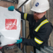
Pulling & Supporting Power & Subsea Cables in the Wind Sector| These cable socks manufactured from offshore/marine grade type 316 Stainless Steel are suitable for use in the renewable energy sector in applications such as cable installation (onshore and offshore), cable support inside wind turbines and cable management – used to pull, protect and support wind turbine cables. Pictured: June 2020 : the first of two export cables, each 37 kilometres in length, has been installed at the nearshore of Thorntonloch Beach as part of construction of the Neart na Gaoithe (NnG) Offshore Wind Farm.
CABLE SOCKS & PULLING PRODUCTS LV MV HV
Complete range of LV, MV and HV cable pulling products for installation and enabling cable jointing in trench or ducts including LV, 11kV/33kV medium voltage (MV), 66kV/132kV high voltage (HV) and EHV transmission and distribution cables up to 400kV.
Thorne & Derrick distribute the most extensive range of Cable Installation & Electrical Distribution Equipmentto the Power Transmission & Distribution industry in the onshore and offshore wind, solar, rail, oil/gas, data centre, battery storage and utility sectors.
We service UK and international clients working on underground cables, overhead lines, substations and electrical construction at 11kV and up to and EHV transmission and distribution voltages.
Earlier this year, Thorne & Derrick welcomed Phil Day from Slingco Limited, the world-leading manufacturer of cable pulling and support socks, swivels, cable protectors, wire rope assemblies and accessories. Phil provided an Offshore Wind focussed company presentation to our Sales Team (pictured left-to-right Sarah Henderson, Carl Cox, Jonathan Hewitt, Phil Day, Jeff Jhanke, Natalie Lundie and Chris Dodds.
Special thanks to Jordan Edmenson at HVPD for the kind permission to republish
Link to the original article can be found here
Partial Discharge
Monitoring & Location on a 33kV Offshore Wind Farm Export Cable
Project
An offshore wind farm operator in the UK requested On-Line Partial Discharge monitoring and cable fault location on two 33kV XLPE land sea export cables to an offshore wind farm. The 33kV circuit began from a grid-connected onshore substation feeding a 2 km long land subsea transition joint, which in turn fed a 12 km 3-core cable directly to the offshore wind farm.
Solution
Short-term continuous monitoring was conducted using an HVPD diagnostic device connected to High Frequency Current Transformer (HFCT) and a Transient Earth Voltage (TEV) sensor.
The HFCT and TEV sensors were installed at the cable terminations during a temporary outage
The HFCT sensors are split core enabling them to be easily installed around the cable core and earth for detection of PD activity within the cable
The TEV is a capacitive probe designed to detect local, high frequency PD pulses originating within the switchgear and terminations
Conducting short-term continuous monitoring over a number of days enables intermittent PD activity to be captured and correlated with other parameters such as load, temperature and humidity.
HFCT and TEV Sensors
Background Theory
If significant levels of PD activity were detected, fault location could be carried out using the cable mapping function of the HVPD diagnostic device. Cable mapping is conducted by detecting the an original PD pulse from the fault location as well as a reflected PD pulse (caused when the original PD pulse reaches the far end of the cable). Using the time delta between these pulses, and the signal propagation speed (which is provided in the cable data sheet) the approximate location of the PD source can be identified.
Results
During the short-term monitoring period, high levels of PD activity were detected with the HFCT on Phase L3 of Circuit 1. Cable mapping on this circuit was then carried out to confirm the location of the fault, with the results indicating that the source was located 800m from the onshore substation.
This result was then corroborated with the cable schedule which confirmed the presence of cable joint no.7 at this location. Based on these findings, it was recommended that the affected joint no.7 be replaced. Following this replacement a forensic analysis on the joints was conducted in which significant insulation damage and tracking within the inner insulation section was found.
Partial Discharge Map Showing PD Location
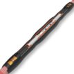
Forensic Examination of Cable Joint
PD Trend Line Before Replacement
PD Trend Line After Replacement
Conclusions and Recommendations
During the short-term monitoring period, high levels of PD activity were detected and cable mapping on this circuit then confirmed the location of the fault. The affected joint was able to be taken out of service and replaced during a scheduled outage, avoiding the risk of an in-service cable failure.
About HVPD
HVPD supplies a comprehensive range of equipment to detect and monitor On-line PD for the condition assessment of in-service power cables, switchgear, motors and generators, and transformers rated at 3.3kV and above. Our PD testing and monitoring technology provide you with an early warning of developing insulation faults, helping you to avoid costly failures and resulting unplanned network outages.
To find out how we can test and monitor your cable network for PD and locate any faults, terminations or joints, get in touch today at [email protected] or call us on 0161 877 6142.
Thorne & Derrick
Specialist Electrical Distributor
Established since 1985, T&D International based in the UK distribute the most extensive range of LV, MV & HV Cable Jointing, Terminating, Pulling & Installation Equipment – contact us today for a competitive quotation.
Compound Box Filling Compound end boxes rarely get attention — until one fails. Across ageing networks, replacement of compound-filled end boxes is becoming more frequent, particularly where original insulation systems have deteriorated and air insulation is not practical because...
Nexans 240–300mm² Multi-Joint – Medium Voltage Cable Joint Installation Medium voltage cable jointing requires reliability, consistency and safe installation practices. The Nexans 240–300mm² Multi-Joint is designed to simplify medium voltage jointing while maintaining high electrical performance for demanding power...


.")