

Blog
11kV Transformers | Bushing Oil Leak on High Voltage Distribution Transformers
March 17th, 2021
Low (LV) to Extra High Voltage (EHV) Power Services to Distribution Networks
Guest Post by Simon Brown
Business Development Manager/33kV Senior Authorised Person at Ipsum Utilities (Private Networks) at Ipsum. Specialising in the installation, maintenance, testing, commissioning and switching of High Voltage networks up to and including 33kV.
If you require any of these services please contact Simon on 07889706194 or [email protected] to discuss your needs.
Transformer Oil Leak
Video | This is an 11kV bushing oil leak on a 500kVA distribution transformer.
Most likely caused by the end gaskets of the bushings having been penetrated and then the rubber flexible boot has held the oil until I released it as seen in the video. We will be isolating the 11kV transformer to drop the oil level below the bushing, remove it and replace its gaskets before putting it all back together – the cork gaskets on either end of the bushing have been penetrated by the transformer oil and it has travelled from the main tank to the 11kV cable box through the bushing. The rubber flexible bushing boot insulating the 11kV cable connection integral to the heat shrink cable termination was holding it back until I released the pressure.
This video demonstrates the critical value of cyclical inspection and maintenance of substation equipment as required by law associated with the installation and on-going maintenance of high and low voltage equipment.
About Ipsum
At Ipsum, we provide specialist infrastructure services across the UK’s regulated water and energy companies and private sector businesses. We work with our customers to maintain, optimise and develop their above and below ground assets to ensure security and resilience, and with our smart systems and ways of working, we ensure we deliver on time, on budget and safely. At Ipsum, we develop long-term working relationships with our customers by providing essential utility services on both public and private networks.
We have many long-term contracts and framework arrangements in place which are built upon great customer service, safe working practices and the ability to flex and deploy specialist skill sets at short notice. The growth of Ipsum has been built upon our people and our ability to meet the demanding and ever-changing needs of our customers.
The UK utility sector is evolving and expanding to meet increasing customer demand, regulatory driven outcomes and to exploit new innovative technologies, at Ipsum we will continue to grow in this sector by being a reliable, flexible and agile service partner that helps customers meet these new challenges.
As we know, utility service provision is not a 9 to 5 business, our customers don’t switch off their networks or assets at night, or at the weekends, or on holidays, or when things are quiet. They need them to work round the clock – and we at Ipsum are right beside them 24/7 to make sure they do. We pride ourselves in providing specialist scheduled maintenance services, being able to respond to an individual call-out or mobilise onto a major upgrade project and that our customers can rely on Ipsum 24/7/365.

Stockists | 11kV 33kV 66kV Joints Terminations Connectors – 3M Pfisterer Nexans
THORNE & DERRICK
Thorne & Derrick are national distributors of LV, MV & HV Cable Installation, Jointing, Substation & Electrical Equipment – servicing businesses involved in cabling, jointing, substation, earthing, overhead line and electrical construction at LV, 11kV, 33kV, 66kV and EHV. Supplying a complete range of power cable accessories to support the installation and maintenance of low/medium and high voltage power systems:
- Slip-on Cable Terminations
- Cold-shrink Cable Terminations
- Heat-shrink Cable Terminations
- Cable Joints – Heat & Cold-shrink
- Separable Connectors (Euromold)
- Surge Arresters & Switchgear/Transformer Bushings
Key Product Categories: Duct Seals | Cable Cleats | Cable Glands | Electrical Safety | Arc Flash Protection | Cable Jointing Tools | Cable Pulling | Earthing | Feeder Pillars | Cable Joints LV | Joints & Terminations MV HV

NFPA-110 Standard for Emergency & Standby Power Systems
March 16th, 2021
NFPA-1100
NFPA-1100 Requirements
-
Special thanks to Franklin Electric for allowing T&D to republish this Article
Franklin Electric is now the leading developer and manufacturer of intelligent monitoring equipment. The 2019 NFPA-110 Standard for Emergency & Standby Power Systems states in Section 8.3.6.1 that the specific gravity of lead-acid batteries be both tested and recorded monthly – copies available of this standard are available on request.
Grid Solutions products include intelligent electronic devices that are designed for online monitoring for the power utility, hydroelectric, and industrial markets – a complete range of MV HV circuit breaker monitoring products are available ensuring uptime, thus considerably reducing the risk and cost that follows power grid downtime.
In addition, NFPA-110 code states that, “Battery CONDUCTANCE testing shall be permitted in lieu of specific gravity testing when applicable or warranted.”
ABOUT CONDUCTANCE TESTING
In simplest technical terms, ohmic technology is based on Ohm’s Law, which expresses the relationship between Volts, Amperes and Ohms in an electrical circuit.
Ohm’s law can be expressed as follows:
Volts (E) = Amperes (I) x Ohms (R).
If any two of the three values of voltage (Volts), current (Amperes) or resistance (Ohms) are known, the third value can be calculated using the above expression of the law.
Thus, Ohmic technology attempts to use voltage and current to determine the resistive characteristic of a battery. Higher resistance equates to a reduced ability to produce current. This characteristic is translated into a measurement of resistance or impedance (Ohms) in some Ohmic technologies; more recent technology uses a converse measurement, called Conductance.

Conductance Testing
Years of laboratory and field-based research found that conductance correlates with battery capacity as measured in a timed discharge test. Since voltage and specific gravity testing are not predictive, timed discharge testing is time consuming and expensive, conductance testing is an effective and economical way of analyzing the health of your battery systems.
Correlation studies have been performed on a significant number of valve regulated AGM and GEL cells, as well as vented flooded cells. These studies have shown that conductance test results are very predictive of battery timed discharge capacity, while voltage measurements are shown to be of little value. This data has been presented to a number of international organizations.
Patented Conductance Technology is the core of our battery testing methodology and recognized as a standard for determining battery state-of-health worldwide.
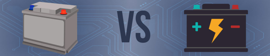
TWO MAIN BATTERY TYPES
Not all batteries are made equal. Have you ever wondered why there are different battery sizes and ratings? Did you know every battery type serves a specific functionality?
The two main battery types are stationary batteries and “starting” batteries. It is very important that you find the correct battery for your particular application, as the wrong choice can affect both the battery’s efficiency as well as its lifespan.
STATIONARY BATTERIES VS ENGINE START BATTERIES
A stationary battery is meant to provide a continuous current of the same intensity for a prolonged time span. In order to do this, they are designed with thick internal plates that slows down the process delivering amperes to the load. Stationary batteries are typically rated in ampere-hours.
An ampere-hour represents the amount of electricity when a current of 1 Ampere passes for 1 hour. The ampere-hour capacity varies with the rate at which the battery is discharged; the slower the discharge, the greater the amount of electricity that the battery will deliver.
A typical rate for ampere-hour capacity is the amount of electricity that a battery will deliver during 20 hours before the voltage falls to 10.50V. For example, a 60Ah battery will deliver a current of 3A for 20 hours.
Starting batteries are just the opposite. They are designed with thin plates so they can provide quick bursts of energy, such as a backup generator or car would need while starting. This only discharges the battery by about 1-3%, which is then topped off typically by an alternator. This is typically known as the battery cranking amps.
Cranking amps are the numbers of amperes a lead-acid battery at 32 degrees F (0 degrees C) can deliver for 30 seconds and maintain at least 1.2 volts per cell (7.2 volts for a 12 volt battery). To recap, stationary batteries provide a lower but longer duration amount of energy, but cannot deliver as many peak cranking amps. Starting batteries are made to provide high power for higher amps, more frequent short draws, and limited long term discharge.
STARTING BATTERY RATINGS
CCA, EN, SAE, JIS, DIN, and IEC
CCA/CA:
CA/cranking amps determine how much power you have to start your engine in most climates. The basic job of a battery is to start an engine; it must crank, or rotate the crankshaft while at the same time maintain sufficient voltage to activate the ignition system until the engine fires and maintains rotation. This requirement involves a high discharge rate in amperes for a short period of time.
Since it is more difficult for a battery to deliver power when it is cold, and since the engine requires more power to turn over when it is cold, the Cold Cranking rating is defined as: The number of amperes a lead-acid battery at 0 degrees F (-17.8 degrees C) can deliver for 30 seconds and maintain at least 1.2 volts per cell (7.2 volts for a 12-volt battery).
CCA/cold cranking amps determine how much power you have to start your engine on cold winter mornings.
EN (EN50342.1A1 Nov 2011 Item 5.3)
Test is performed at -18°C. The EN requirement is however split into two levels EN1 and EN2.
EN1: The battery is required to meet a voltage of 7.5V after 10 seconds and after 10 seconds rest, the battery is further discharged @ 0.6 x original current and is required to complete 73s in the second stage giving a total combined discharge period of 90 seconds (assume initial period equates to (10s/0.6) 16.7 seconds.
EN2: As EN1 except that the second discharge period to 6.0V should achieve 133 seconds giving a total time of 150 seconds. The discharge current’s ability to meet both designs is very much subject to battery design and can vary from manufacturer to manufacturers and design to design.
SAE (J537 Jun 1994 American Standard)
This is the starting test according to the SAE (Society of Automotive Engineers). The test specifies that the battery at a temperature of –18°C will deliver a current equal to the Cold Cranking Amps for 30 seconds with the voltage staying above 7.2 volts (3.6 volts for a 6 volt battery).
JIS (D5301: 1999)
The Japanese Industrial Standard test is carried out at -15°C. The starting batteries are usually tested at either 150A or 300A with different 10s /30s voltage and durability requirement to 6V.
DIN (German Industrial Standard at -18°C)
As with SAE the test is carried out at -18°C. The fully charged battery is discharged to 6V with the rated test current. The voltage must be at least 9.0V after 30 seconds and the time to achieve 6V must be at least 150 seconds.
IEC (International Electro Technical Commission) (IEC 60095-1 Nov 2006)
The test is performed at -18°C .
After a rest period of up to 24 hours after preparation according to 6.2 of standard, the battery is placed in a cooling chamber with air circulation at a temperature of -18°C +/- 1°C until the temperature of the middle cell has reached -18°C +/- 1°C.
The battery is then discharged according to the standard and is required to meet a voltage of 7.5V after 10seconds and 7.2V after 30seconds, the battery is then rested for 20+/-1 seconds after which the battery is discharged at 60% of the original current and is required to meet a voltage of 6V after 40 seconds, in accordance with table 7 of the standard.
THE RIGHT TOOL FOR THE JOB
Just like finding the right battery for the job, you must find the correct battery analyzer to test the battery.
Utilizing Battery Conductance To Meet NFPA-110 Battery Maintenance Requirements
The CELLTRON GENSTART uses conductance technology that correlates the battery test output results to the selected engine start battery rating under test, thus executing a conductance test with the battery results matching the selected battery rating set by the user including CCA, EN, SAE, JIS, DIN, and IEC.
Conductance is our patented core technology and an excellent indicator of state of health making the CELLTRON GENSTART a solid choice for maintaining the critical power standard of 24/7/365.

CELLTRON GENSTART
Meeting NFPA-110 & NFPA-111 Maintenance Requirements
The CELLTRON ADVANTAGE is a user-customizable, economical battery management tool for service providers, operations, and maintenance teams capable of testing Valve Regulated Lead Acid (VRLA) and Vented Lead Acid (VLA) batteries.
KIT Configurations To Meet NFPA-110:
- CAD 5000 KIT: With Genstart Module Add-On
- CAD 5200 KIT & CAD 5500 KIT: Standard
All Kit Configurations Meet NFPA-111 Requirements.
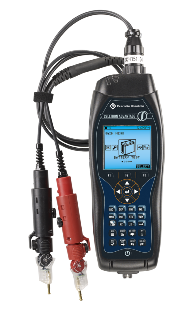
CELLTRON ADVANTAGE
Features:
- Pateted conductance based diagnostics
- 50% reduction in test time
- Less invasive testing approach
- Compatibility with CELLTRAQ Battery Data Management Software for simple data tracking, reporting, and decision making
- Field software updates, including module add-ons

Franklin Electric Grid Solutions work to provide the expertise to reduce the risks of power grid downtime.
Franklin Electric provides a range of utility grid solutions including circuit breaker monitors and load tap changers. Circuit breaker monitors including the Incon Optimizer 2 and the Incon Optimizer 3 feature award-winning, SF6 gas monitoring technology.
Overview of Monitoring Devices for HV Circuit Breakers
The following Franklin Electric products are available from Thorne & Derrick – contact us for further information.
- HV Circuit Breakers Monitors | Franklin Electric Incon Optimizer 2
- HV Circuit Breakers Monitors | Franklin Electric Incon Optimizer 3
- HV Load Tap Changers | Franklin Electric Incon 1250 LTC
- HV Load Tap Changers | Franklin Electric Incon 1250B LTC
- HV Load Tap Changers | Franklin Electric Incon 1511 LTC
- HV Power Grid Monitoring | GridSense Line IQ
THORNE & DERRICK
Thorne & Derrick are national distributors of LV, MV & HV Cable Installation, Jointing, Substation & Electrical Equipment – servicing businesses involved in cabling, jointing, substation, earthing, overhead line and electrical construction at LV, 11kV, 33kV, 66kV and EHV. Supplying a complete range of power cable accessories to support the installation and maintenance of low/medium and high voltage power systems:
- Slip-on Cable Terminations
- Cold-shrink Cable Terminations
- Heat-shrink Cable Terminations
- Cable Joints – Heat & Cold-shrink
- Separable Connectors (Euromold)
- Surge Arresters & Switchgear/Transformer Bushings
Key Product Categories: Duct Seals | Cable Cleats | Cable Glands | Electrical Safety | Arc Flash Protection | Cable Jointing Tools | Cable Pulling | Earthing | Feeder Pillars | Cable Joints LV | Joints & Terminations MV HV
Using Astute HV Monitoring To Target Maintenance
March 16th, 2021
HV Montioring Of Cables & Switchgear
Astute® HV Service
Failure of your high-voltage switchgear and cabling could cost millions in repairs, replacements and fines. But most cable failures don’t happen in a flash – they can be predicted from warning signs, most notably partial discharge (PD).
By watching your cables and switchgear, EA Technology’s Astute® HV service can alert you to suspicious spikes and pinpoint which parts of your HV system should be investigated.
The below case study shows how a major UK utility company decided to keep a cautious eye on their HV assets by using the EA Technology Astute® HV monitoring service through continuously partial discharge monitoring.
Background
Our client is a major UK utility company that owns and operates electrical networks supplying 1.4 million customers. As such, they are responsible for maintaining electrical assets and repairing faults in a safe and prompt manner. Failure to do so can cause supply interruptions, which is costly to our client and frustrating for their customers.
Most electrical asset failures are not instantaneous but develop slowly over time. These failures can be predicted by searching for distinct signatures, most prominently, partial discharge (PD).
PD is commonly caused by the breakdown of asset insulation, which leads to electrical currents propagating through the insulation, which further deteriorates insulation; this is a cyclic process which inevitably leads to faults. With the right equipment installed, PD can be detected, and failures can be avoided before they cause unplanned outages.

EA Technology specialises in producing and managing hardware that monitors PD in high voltage networks. The Astute HV Monitoring® system is a comprehensive monitoring package that includes:
- Astute HV Monitoring® hardware
- A software platform to manage asset monitoring
- Remote monitoring by EA Technology
- Expert interpretation of results
- Automatic email and text alerts
- Advice from experts in the field
One large HV substation owned by our client had a history of PD activity and asked EA Technology to investigate.

Our Approach
The substation in question was home to a very large, and ageing switchboard (with 50 panels/circuits). To investigate the suspected PD, an Astute HV Monitoring® system was installed to monitor every panel of the switchboard. In total, over 150 sensors were installed to pinpoint the exact location of the faulty equipment.
The data collected by the sensors triggered automatic alarms and were subsequently analysed by our expert data team remotely. Our team identified four panels that showed clear signs of PD and were in instant need of intervention. The PD signals for these panels are shown in the graph overleaf. This information was passed on to our client in a timely fashion, who took action to investigate this further.
Entering HV substations known to house defects poses many risks. Therefore, before investigating the faults, the Astute HV Monitoring® dashboard was used to view recent data as part of the risk assessment on entering the substation.

Astute HV Monitoring Dashboard
The panels identified by the monitoring system were targeted to be investigated individually. It was immediately evident that the old insulation had broken down; this is shown in the figure above. The centre of the wooded insulator displays scorched burning marks, which is indicative of PD activity.

Degraded insulation, leading to partial discharge
The faulty insulators were promptly replaced with modern, high-density polyethylene insulation, as shown in the figure below. With the monitoring devices still in place, data was continuously collected and analysed to evaluate if the PD issue was solved. The results showed healthy ultrasonic readings with no signs of PD.
Client Benefits
The Astute HV Monitoring® system was successfully deployed to identify 4 specific panels (out of a total of 50) at risk of future faults. This allowed our client to prioritise the maintenance of their assets, ultimately saving time and money, and ensuring a reliable electricity supply for the thousands of customers connected to this substation.

Average ultrasonic readings activity of the four suspect panels
Now that the monitoring system is in place, our client can rest assured that any future PD-related issues will automatically be detected and raised before assets fail. The exact cost savings for such catastrophic asset failures is difficult to estimate, but regulatory financial penalties for supply interruptions can reach hundreds of thousands of pounds for a single occurrence.

Astute HV Diagram
About EA Technology
EA Technology’s mission is to promote the development of resilient, accessible, low cost energy networks globally, accelerating the transition to energy decarbonisation.
EA Technology is a specialist in asset management solutions for owners and operators of electrical assets. Headquartered in the UK, our operations and customers are global with four regional offices around the world. We originated in 1966 as a groundbreaking research and development organisation serving the electricity industry.
We are committed to providing our customers with innovative products and services, consultancy and training which deliver tangible benefits for their businesses enabling them to create safer, stronger and smarter networks for today and the future.
We work with many clients on a long-term basis to safeguard their power networks. We can advise on strategy and implementation solutions using a range of products, providing an ongoing service to ensure the reliability of equipment, together with highly trained customers’ staff in specialist areas. Our software helps our customers to manage their assets to achieve maximum life and reduce costs.
Thorne & Derrick
Thorne & Derrick are national distributors of LV, MV & HV Cable Installation, Jointing, Substation & Electrical Equipment – servicing businesses involved in cabling, jointing, substation, earthing, overhead line and electrical construction at LV, 11kV, 33kV, 66kV and EHV. Supplying a complete range of power cable accessories to support the installation and maintenance of low/medium and high voltage voltage power systems:
- Slip-on Cable Terminations
- Cold-shrink Cable Terminations
- Heat-shrink Cable Terminations
- Cable Joints – Heat & Cold-shrink
- Separable Connectors (Euromold)
- Surge Arresters & Switchgear/Transformer Bushings
Key Product Categories: Duct Seals | Cable Cleats | Cable Glands | Electrical Safety | Arc Flash Protection | Cable Jointing Tools | Cable Pulling | Earthing | Feeder Pillars | Cable Joints LV | Joints & Terminations MV
WEBINAR: Managing Risk for Successful Underground Transmission Projects
March 16th, 2021
FREE WEBINAR – REGISTER HERE
Underground Transmission Projects
WEBINAR
How Do you Manage Risk For Underground Transmission Projects?
Burns & McDonnell, one of PDi2’s member organizations, is sponsoring a free webinar on March 30th. The discussion will focus on the risks typical to underground transmission projects and how to manage those risks during various stages of the project.
WEBINAR: Tuesday, March 30, 2021 | 11AM ET / 8AM PT
REGISTER HERE
Underlying any construction project, inherent risks exist.
For underground transmission projects, risks can range from subsurface conditions to existing utilities to interface points and more.
What can an organisation do to mitigate these risks throughout the project life? Risk mitigation can occur through multiple avenues including site investigations, contracting strategies, design and even construction.
This presentation will discuss risks to typical underground transmission projects and how those risks can be managed during various stages of project delivery.
Additionally, the presentation will explore unique risks to subsea cable projects and how engineer-procure-construct (EPC) project delivery for underground transmission projects can be a beneficial project approach.
Speakers:

Tyler McArthur, PE, ENV SP, Civil/Structural Engineer, Burns & McDonnell
Tyler McArthur is a civil/structural engineer in the underground transmission group at Burns & McDonnell. His responsibilities include cable duct bank design, underground routing analysis, cable pulling tension calculations, duct bank construction estimates and underground transmission line construction support.
His work includes use of cable pull 3D design/analysis software packages and several in-house design and cost estimating programs. Tyler also has experience working in the firm’s overhead transmission and substation groups.

Nathan Rochel, PE, P.Eng, Electrical Engineer, Burns & McDonnell
Nathan Rochel is an electrical engineer specialising in the design of underground transmission lines and management of the underground transmission department.
He has been involved in the design of underground transmission projects ranging from 5-kV through 500-kV. His experience includes all aspects of underground transmission design, including front-end planning, routing, permitting and feasibility, through detailed design, construction support, commissioning and testing.
Nathan’s project experience has covered investor-owned utility transmission installations, developer interconnects, renewable installations (solar, wind and offshore wind), inside station connections, industrial installations, trenchless installations, generation ties and more.

David Slee, Program Manager, Burns & McDonnell
David Slee is a program manager specializing in the installation and protection of marine cables, pipelines and structures at Burns & McDonnell.
He has more than 30 years of experience in the implementation and connection of renewable and nonconventional energy to the grid.
David has provided consultation services to several utilities and businesses in the energy sector, in particular offshore wind with associated cabling, wave and tidal energy, and some onshore renewables.

Burns & McDonnell is a full-service engineering, architecture, construction, environmental and consulting solutions firm, based in Kansas City, Missouri.
Transmission & Distribution World’s mission is to provide utility executives, managers, engineers, supervisors, operators and linemen with must-read information on:
- Design
- Engineering
- Construction
- Operation
- Maintenance of the Electric Power-Delivery Systems
THORNE & DERRICK
Thorne & Derrick are national distributors of LV, MV & HV Cable Installation, Jointing, Substation & Electrical Equipment – servicing businesses involved in cabling, jointing, substation, earthing, overhead line and electrical construction at LV, 11kV, 33kV, 66kV and EHV. Supplying a complete range of power cable accessories to support the installation and maintenance of low/medium and high voltage power systems:
- Slip-on Cable Terminations
- Cold-shrink Cable Terminations
- Heat-shrink Cable Terminations
- Cable Joints – Heat & Cold-shrink
- Separable Connectors (Euromold)
- Surge Arresters & Switchgear/Transformer Bushings
Key Product Categories: Duct Seals | Cable Cleats | Cable Glands | Electrical Safety | Arc Flash Protection | Cable Jointing Tools | Cable Pulling | Earthing | Feeder Pillars | Cable Joints LV | Joints & Terminations MV HV
Cleating 11kV 3 Core & Single Core Cables With LV Pilot Cables
March 16th, 2021
Cable Cleats
Image Courtesy Of: Sam Rowe – Estimator at F B Taylor (Cable Contractors) Ltd
These 11kV cables have been pulled in and cleated using stainless steel trefoil and 2 bolt nylon cable cleats to ladder racking.
Cable cleats are used to fix, clamp and support cables – cleats provide effective short circuit protection, support and retention to LV, MV and HV power cable systems when installed at intervals to circuits to secure electrical installations.
The cable cleats provide restraint and prevent excessive cable movement resultant from fault-current magnetic forces – cleats must be suitably rated for cable size (outside diameter) and anticipated fault current (peak fault level kA).
Correctly specified cable cleats will withstand the forces corresponding to the values of the peak prospective short-circuit current.
Power cable system designers, engineers and specifiers must consider the correct cable fixing or securing system to provide safe and adequate restraint and protection of LV, MV or HV cables – cable cleats restrain movement of cables during electrical fault conditions.
Cable cleats are available to suit all environmental conditions (onshore and offshore), industrial applications and operating voltages – specialist cable fixings for fire resistant, low smoke zero halogen (LSF LSOH) and quadrafoil (Quad) cable installations.
![]()
Jointers blog
Subscribe now to our POWER NEWSLETTER– a monthly email circulation packed with news, projects, videos, technical tips, training information, promotions, webinars, career opportunities and white papers.
Includes access to our popular JOINTERS BLOG with contributions from utility professionals, linesmen and cable jointers working on MV HV EHV cables and overhead lines typically at 11kV, 33kV, 66kV and up to 132kV.
15,000+ Subscribers. ➡ 
