

Blog
Medium Voltage Training | Reducing Defects In Cable Networks
December 8th, 2021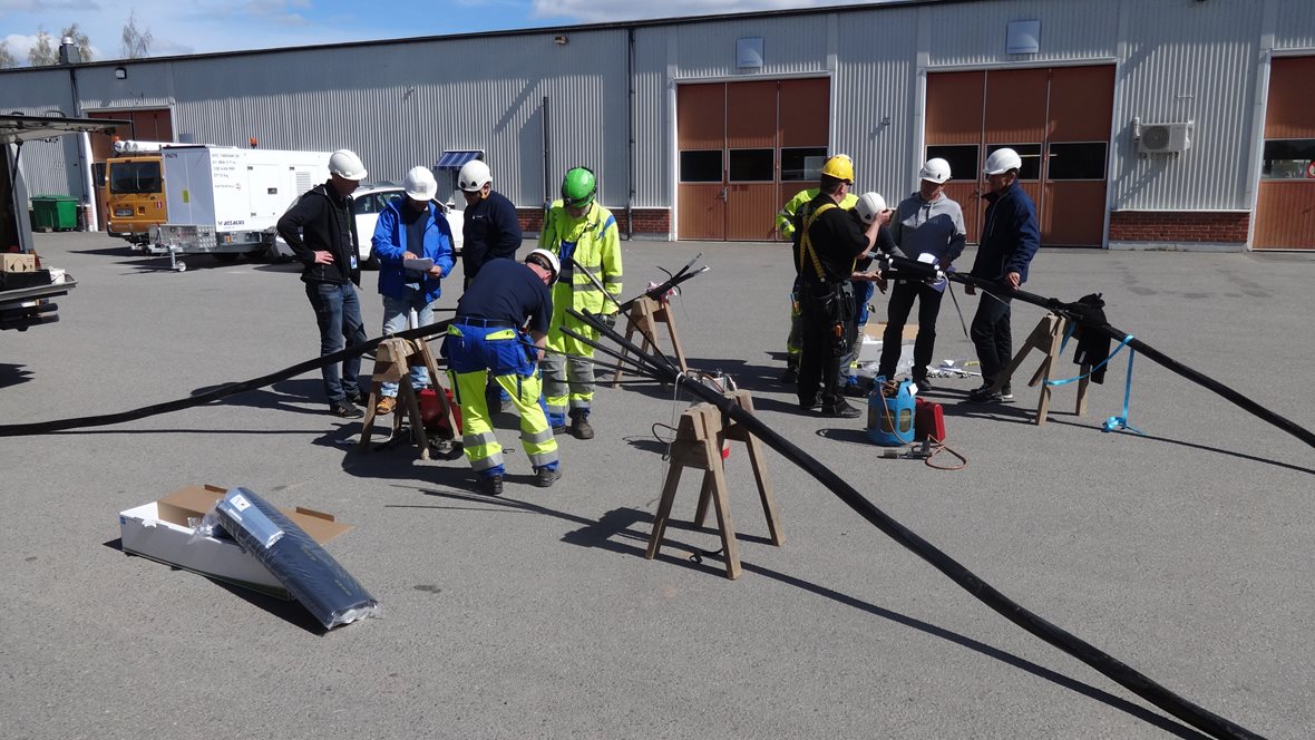
The following blog has been republished with kind permission of Angelo Roviello, Area Sales Manager at Ensto, about the importance of Medium Voltage Training for Installers.
Medium Voltage Training for cable Network Installers

Malpractices during the installation of cable accessories are the main cause of interruptions and faults. The solution is sharing our know-how with the installers.
The use of high-quality cable accessories is a prerequisite for reliability in medium voltage cable networks. However, since most interruptions are due to the installation process, proper and systematic training of installers is needed in order to reduce the number of medium voltage power cable and system faults.
The electrification of continuously growing urban areas is based on cable networks, and in rural areas overhead lines are gradually moving underground. Constant shortage of power professionals and cable jointers brings in installers with various backgrounds.
At the same time, cable accessories have been developed into complete packages with product-specific installation instructions. A trained professional knows the importance of on-site preparations such as protecting against dirt and water. He also follows the installation instructions carefully to make the joint or ending last as long as the cable itself.
MV Cable Training Reduces Costs
It is estimated that more than two thirds of unexpected interruptions in cable connections are due to faulty installation. In Central Europe, for example, the cabling activity is on high level, and the situation might be even worse.
Leading utilities look for a solution in two ways – by selecting tested, high-quality products, and by applying systematic product training of installers. They know that by improving the quality of installation work, the costs can be reduced significantly in the long run.
Ensto has been providing installation training for more than ten years in various markets. The concept is called Ensto Pro and includes events that consist of both theory-based lessons and hands-on installation exercises.
It is estimated that more than two thirds of unexpected interruptions in cable connections are due to faulty installation.
The products, in turn, are tested in accredited laboratories in accordance of international standards, and in addition to that, continuously in-house to ensure quality. The installation instructions are based on visual images to clearly point out critical steps and measures.
The final goal of all this is a correct installation, reliable operation of the network and lower total cost of ownership for the customer.
Proven Results in Sweden
Ensto in Sweden has experience of systematic product training of medium voltage cable accessories since 2012.
“At that time large utilities had failures in their networks, and it was soon realized that they were not due to the product itself. These utilities welcomed our installation training, received excellent results and remain loyal customers today,” says Björn Gustafsson, Sales Director of Ensto in Sweden.
“Several years ago, one of the largest network owners in the country required its contractors to have all their installers trained on our products every four years. Now many other customers are doing the same,” he says.
Medium voltage accessory training is usually held on or near customer premises. The day starts with cable theory, sharing experiences and going through the steps of installation. After lunch is a time for hands-on installation in small groups. Gustafsson and the team organize trainings almost every week covering nearly all Swedish customers.
This also means that the Ensto team and installers know each other well, and it is easy to pick up a phone and call.
“Some installers have already been trained for two or three rounds. They still find the day very rewarding and an excellent opportunity to discuss and learn something new for their daily work.”
“Also, the customer feedback is encouraging. One of our long-standing customers trained all the installers to cold shrink joints. After that, there was not a single cable joint failure, no more penalties and no replacement costs. The installers were also delighted with their improved skills.”
LV, MV & HV JOINTING, EARTHING, SUBSTATION & ELECTRICAL EQPT
Thorne & Derrick International are specialist distributors of LV, MV & HV Cable Installation, Jointing, Duct Sealing, Substation & Electrical Equipment – servicing UK and global businesses involved in cable installations, cable jointing, substation, overhead line and electrical construction at LV, 11kV, 33kV and EHV.
THORNE & DERRICK Product Categories: Duct Seals | Cable Cleats | Cable Glands | Electrical Safety | Arc Flash Protection | Cable Jointing Tools | Cable Pulling | Earthing | Feeder Pillars | Cable Joints LV | Joints & Terminations MV HV
Partial Discharge On Outdoor Terminations | Case Study
December 8th, 2021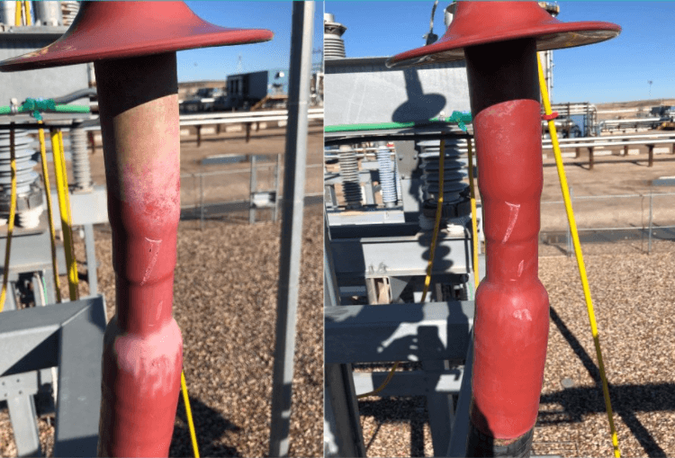
Cable termination H3 | Uneven contamination before and shown after cleaning
Partial Discharge
-
Special Thanks To William Higinbotham President at EA Technology for allowing T&D to republish
Below is a great example of using partial discharge instruments to prevent failures without doing unneeded maintenance.
Contamination of cable terminations
causes partial discharge
Cable terminations are often used outside on riser poles or substation structures to convert cables to overhead lines or busses. These terminations convert the very tightly controlled cable electric field into an uncontrolled air insulated application.
When applied properly, the field strengths are less than the insulation strength and therefore no partial discharge exists.
Under certain circumstances, even a well applied termination can have partial discharge as a result of contamination. Humid salt air leaves conductive deposits that often result in partial discharge. Because of this, terminations in coastal areas are highly prone to PD. Other types of contamination can result from pollution, or even dusty air. When an insulator gets unevenly coated in hydrophilic contamination, you can get what is called dry band discharge.
The uncontaminated sections of insulator tend to be hydrophobic, so the insulator has dry and wet areas that are insulating and conductive. This disturbs the field distribution and leads to discharge across the dry bands.
Given time this will erode the insulator and lead to flashover.
The challenge
A high voltage asset owner in central Canada has numerous terminations on substation structures. Clearly salt contamination is not the issue. However other contamination is building up unevenly on their cable terminations.
This operator is very proactive and does periodic PD surveys of both indoor and outdoor assets as part of their regular preventative maintenance. They use the EA Technology UltraTEV Plus2 with the UltraDish attachment for scanning terminations from the ground.
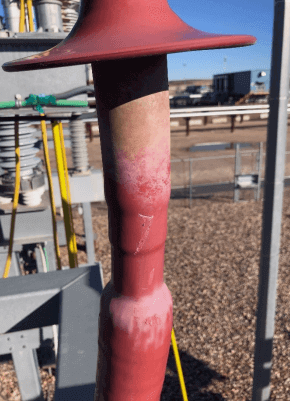
Cable termination H3 with uneven contamination
The test results
Two of the terminations (H1 and H3) scanned returned very high levels of ultrasonic energy. The phase resolved plots show typical PD results. The source is frequency locked to the power system and the impulses are occurring twice a cycle, half a cycle apart. The levels are approaching 40dBuV which is very high. The ANSI/NETA MTS 2019 standard calls for immediate action on levels greater than 6 dBuV.
Action taken
During the next scheduled outage, the insulators were cleaned and then rescanned. The ultrasonic energy was gone, proving that the discharge was a result of the contamination.
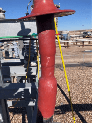
Cable termination H3 after cleaning
The benefits
The immediate benefit is that these terminations are now less likely to fail. Long term the asset owner has learned how the PD survey process can be used to control cleaning cycles. Some terminations may need less frequent cleaning some may need more.
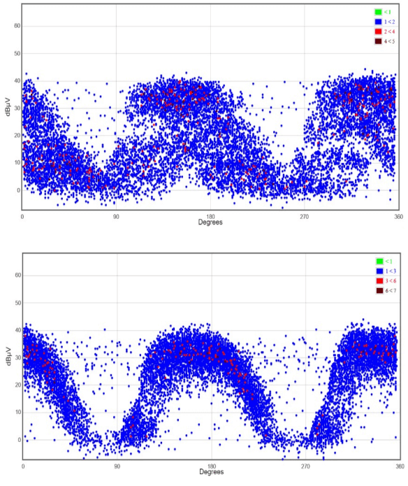
Ultrasonic PD results prior to cleaning
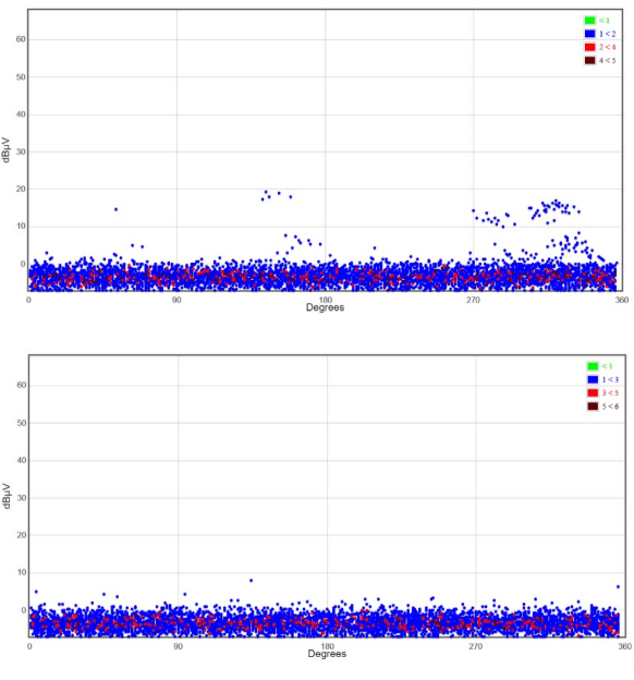
Ultrasonic PD results after cleaning
EA Technology
William G. Higinbotham has been President of EA Technology LLC since 2013. His responsibilities involve general management of the company, including EA Technology activities in North and South America. William is also responsible for sales, service, support, and training on partial discharge instruments and condition-based asset management. He is the author or co-author of several industry papers.

Thorne & Derrick
Thorne & Derrick International are specialist distributors of LV, MV & HV Cable Installation, Jointing, Duct Sealing, Substation & Electrical Equipment – servicing UK and global businesses involved in cable installations, cable jointing, substation, overhead line and electrical construction at LV, 11kV, 33kV and EHV.
THORNE & DERRICK Product Categories: Duct Seals | Cable Cleats | Cable Glands | Electrical Safety | Arc Flash Protection | Cable Jointing Tools | Cable Pulling | Earthing | Feeder Pillars | Cable Joints LV | Joints & Terminations MV HV
- Scope –single-source supply of extensive range of products
- Stock – a multi-million pound stock holding provides complete global supply solutions
- Staff – technical support from a trained, proactive and friendly team
- Delivery – UK stock turnaround with express logistics to all international destinations


Stockists for Nexans Euromold | Pfisterer Connex | 3M Cold Shrink
Offshore Wind & Subsea Power Cables | Market Trends by ORE Catapult
December 1st, 2021
The following article, exploring offshore wind subsea power cables, has been republished with the kind permission from the authors: Othmane El Mountassir & Charlotte Strang-Moran from ORE Catapult | Published September 2018 | AP-0018
Installation, Operation & Trends
By the end of 2018, installed offshore wind power capacity will reach a total of 30.2GW, with 22.9GW of generation in Europe and 7.3GW across the rest of the world. The UK remains the global leader in offshore wind, with a total capacity of 6,385MW and an additional capacity of 3.2GW entering operation by 2020. As the industry’s generation capacity continues to grow, so does the need for developing reliable, high-capacity transmission cable technologies.
Subsea power cable failure is frequently reported as an issue for offshore wind farm operators. Such failures are reported to account for 75-80% of the total cost of offshore wind insurance claims – in comparison, cabling makes up only around 9% of the overall cost of an offshore wind farm. A lack of available data on cable failures led ORE Catapult to develop an interactive tool for internal use, which captures information about UK offshore wind projects and their power cables’ lifecycle from the installation to the operational phase.
This paper summarises some of the most pertinent insights on cable failures gleaned from the Catapult’s use of the tool and sets forth suggestions on how to improve knowledge-sharing in the offshore wind community to reduce the impact of future failures.
Headlines
- The UK’s operational offshore wind farms are using 62 export cables totalling a length of 1,499km and over 1,806km of inter-array cables to transport the 6,385MW of electrical generation.
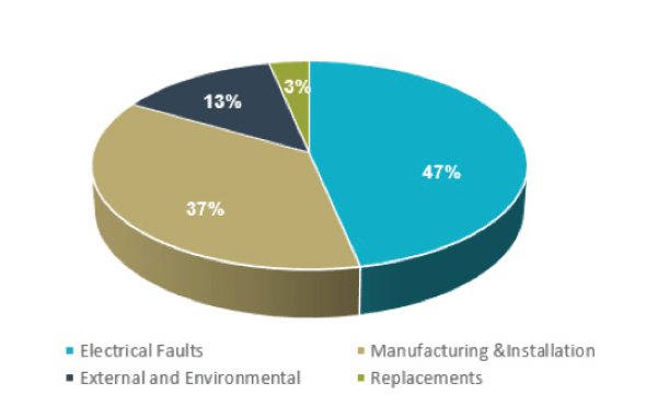
- A total of 43 array and export cable failures have been reported since 2007. Issues associated with manufacturing and/or installation are reported to be the most common cause of cable failure.
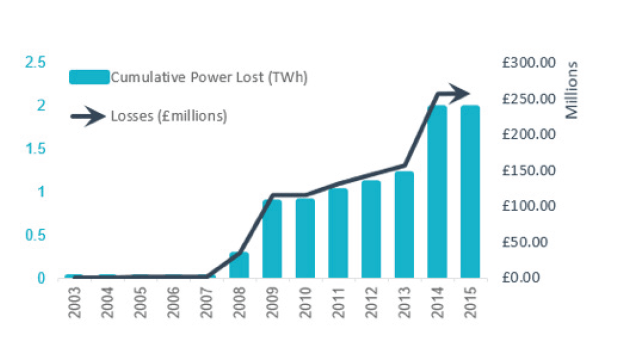
- From 2014 to the end of 2017, recorded cable failures at UK offshore wind projects have led to a cumulative loss of power generation of approximately 1.97TWh.
UK Offshore Wind Trends
The UK generates more electricity from offshore wind than any other country in the world. Operational offshore wind farms are currently generating 6,738MW using 1717 turbines.
In 2017, the UK installed 1681MW, representing more than half of the new offshore wind power capacity built in Europe. It is forecasted that by 2020, there will be a record-breaking year for new capacity – largely driven by delayed wind farms and the deployment of large-capacity turbines in the 7MW 8MW range. The following figures provide an insight into current UK offshore wind sector trends.
Wind Development: By the end of 2018, installed offshore wind power capacity will reach a total of 30.2GW worldwide, with 22.9GW of generation in Europe and 7.3 GW in rest of the world. The UK remains the European country with the largest installed capacity, reaching a total capacity of 7,851 MW by the end of 2018.
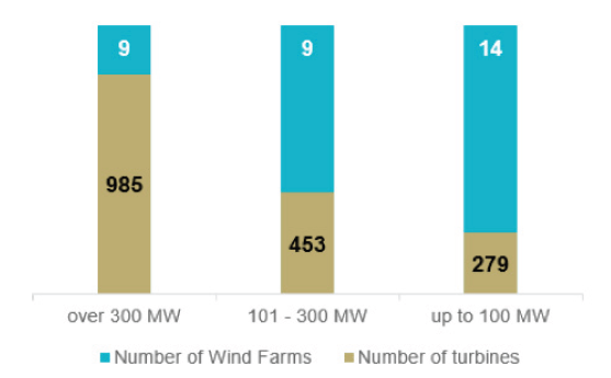
Farm Capacity: By categorising wind farms into three ranges of generation capacity, it can be seen that the larger the capacity range of the wind farms, the higher the number of wind turbines being used. It is expected that this trend will change with the deployment of higher-capacity turbines, reducing the number required.
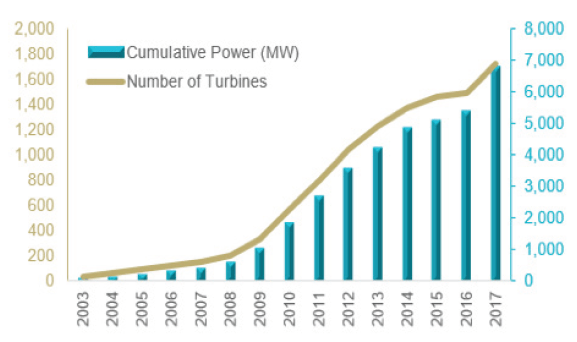
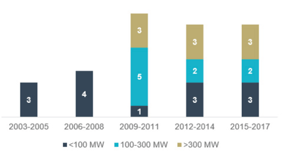
Progressive Trends: Since the development of the first demonstrator projects in 2003, the UK’s offshore wind sector has witnessed strong growth, supported by government incentives and investor confidence in the sector. This can be demonstrated in the figure above, where we can see over the years an increase in the number of offshore wind farms and demonstrators with different generation capacities.
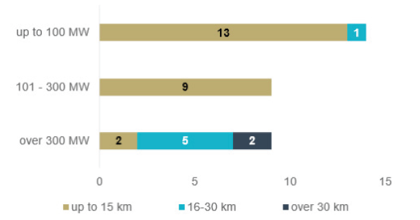
Distance from Shore: The UK’s geographic location makes it ideal for offshore wind generation. Early developments from the Round 1 and Round 2 leasing phases were relatively small and close to shore. In contrast, recent projects and future developments have seen and will see this distance increase to the 50-90km range from shore to take advantage of the wind strength in these areas.
Subsea Cable Trends
The rapid growth of the offshore wind sector has led to the development of a number of new subsea cable technologies. This was mainly supported by a robust cable-related supply chain with leading organisations in manufacturing, services and academia present across the UK. The demand for subsea power cables will continue to grow at a fast pace to support both future offshore wind development and the subsea power interconnector sector.
Export Cables are vital for transmission of the generated power to the grid. The UK’s operational offshore wind farms are using 62 export cables totalling a length of 1,499km. The voltage levels of these cables range from 33kV for nearshore wind farms without offshore substations, and up to 132kV, 150kV and 220kV for further-offshore sites with one or two substations.
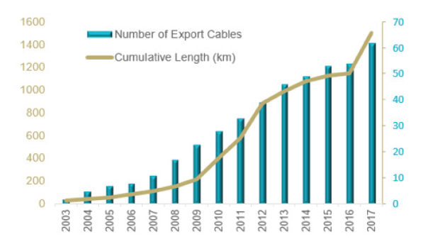
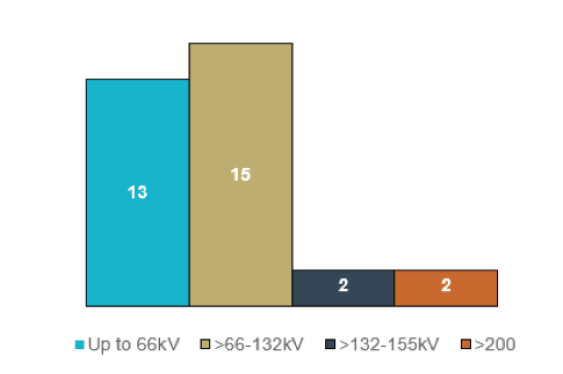
Export Cable Trends: Research and development activity has led to the development of new cable technologies. Since 2013, over 80% of projects in Europe have deployed export cables with a voltage greater than 150kV. Reflecting the rapid development of cable technologies, 80% of projects commissioned in 2018 will be using cables with a voltage level greater than 200kV.
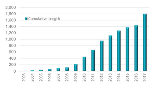
Array Cable Development: There are over 1,806km of inter-array cables in UK waters. To maximise generation revenue and achieve Levelised Cost of Energy reductions, offshore wind projects will continue to increase in size.
As such, the lengths of array cabling used is expected to increase due to the increased number of turbines and the distance between them.
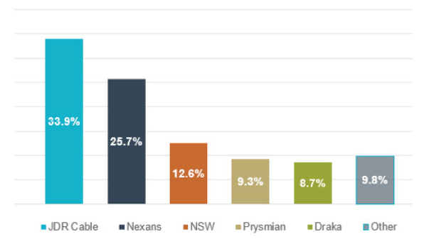
Array Cable Manufacturers: The cable market is generally global in nature and there are a number of suppliers available. A notable UK success has been achieved with JDR cables, which has supplied numerous UK offshore wind projects, as well as several overseas projects. The expansion of the market and growth of an indigenous UK supply chain is expected to help reduce costs.
Cable Failure Trends
According to industry data obtained by the Catapult, cables account for the largest number of insurance claims in the offshore wind sector. Though subsea cable failures are reported often, publicly-available information remains scarce. The following figures, gleaned from the Catapult’s internal cable database, provide an insight into reported subsea power cable failures in the UK’s offshore wind sector.
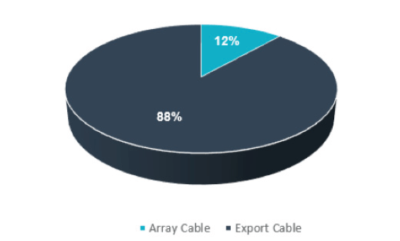
Cable Failure: Incidents relating to the installation and operation of subsea power cables are found to be the most costly cause of financial losses in offshore wind industry. Since 2007, 43 known failures of wind farm array and export cables were reported. The issues associated with these failures vary in nature.
Causes of Failure: Issues associated with the manufacturing and/or installation phase are reported to be the most common cause of cable failure. The failure events reported include cases where unplanned faults have occurred, or when planned, pre-emptive repairs have been required to avoid the likelihood of fault.
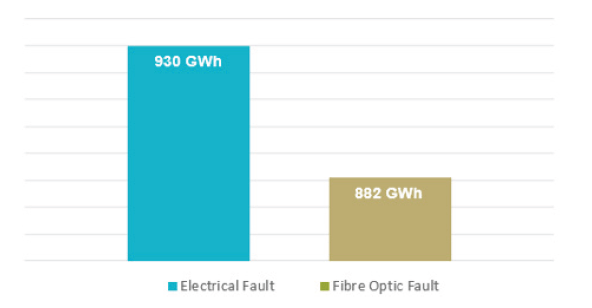
Fibre Optic and Electrical Faults: In the UK’s offshore wind sector, recorded faults of electrical origin were found to be higher than fibre optics failures. To date, power losses due to fibre optics failure reached an estimated value of 600GWh, while losses due to electrical faults were estimated at 1,160GWh. It should be noted that electrical failures may sometimes lead to the failure of fibre optics.
Costs of Failure: The cost of a cable failure can be considerable, taking into account repair costs and generation revenue loss. From 2014 until the end of 2017, recorded cable failures at UK projects have led to a cumulative generation loss of approx. 1.97TWh, equating to approx. £227M*. This figure demonstrates beyond doubt that the sector is still in need of innovative cable installation and repair technologies. *Based on a strike price of £115/MWh.
Discussion and Next Steps
The UK has a robust subsea cable-related supply chain, encompassing manufacturing, service providers and academia. However, there is still a lack of communication between stakeholder groups. For example, the standardisation of cable installation practices may lead to fewer installation issues, while the dissemination of learned experiences can be used to predict or avoid certain failures and also bridge innovation gaps in manufacturing. However, this is only possible if the parties involved are willing to share the required records. There is a consensus from market stakeholders that subsea cable project activities are currently dispersed, and a more structured and co-ordinated process is required to pull promising technology and ideas through development and demonstration. However, proposed concepts aimed at developing a subsea cable database, which informs and enables stakeholders to identify and bridge gaps in innovation – has been met with scepticism from a number of systems owners and operators; questions remain over whether a live, regularly-updated database would be providing ongoing value and longevity.
To ensure the successful development and implementation of appropriate technologies and processes aimed at reducing cable failures within the offshore wind industry, ORE Catapult is acting as a driver for a number of initiatives such as the Offshore Wind Innovation Hub, subsea cable innovation challenges, and technology demonstration opportunities for SMEs at its Levenmouth Demonstration Turbine. The Catapult also anticipates launching a publicly-available web-based platform dedicated to subsea power cables. To help solve some of the challenges around offshore wind subsea cable applications, ORE Catapult has developed a dedicated internal database and an Offshore Wind Innovation Hub strategic programme dedicated to subsea power cables and future systems. The aim of the internal cable database platform is to provide quantitative information and evidence to support building a consensus to solve common cable issues, while the Offshore Wind Innovation Hub was established to co-ordinate the sector’s innovation needs and provide a comprehensive view of the research funding opportunities available.
It is beyond question that the offshore wind sector will continue to expand further over the coming decades. Future wind farms will make use of higher-capacity turbines and will be located further offshore: with that comes the requirement for robust cable technologies and safe installation and operational practices. The sector must learn from the wider industry and share information and lessons learned so that costs can continue to fall, helping the wider offshore wind supply chain continue its trajectory of growth.
Further Reading
Lead-Free Cables | The Future for Offshore Wind Farms
Providing Electrical Safety & PPE to Offshore Wind Farm Workers
Pipe & Cable Seals for Offshore Windfarm Substations, Enclosures & Foundation
LV, MV & HV JOINTING, EARTHING, SUBSTATION & ELECTRICAL EQPT
Thorne & Derrick are Specialist Distributors to the UK and international Offshore Wind & Renewable industry to provide safe and reliable LV HV Electrical Cable & Power Distribution Systems up to 66kV – we are highly customer responsive and absolutely committed to providing a world-class service.
Contact our UK Power Team for competitive quotations, fast delivery from stock and technical support or training on all LV-HV products.
Key Product Categories: Duct Seals | Cable Cleats | Cable Glands | Electrical Safety | Arc Flash Protection | Cable Jointing Tools | Cable Pulling | Earthing | Feeder Pillars | Cable Joints LV | Joints & Terminations MV HV

See how T&D support, supply and service the Renewable Energy industry.

MV HV Cables 11kV 33kV 66kV | Cable Joints, Terminations & Connections
NEW | Ripley Cable Stripping Tools to Improve Safety & Reliability
November 23rd, 2021
NEW Ripley Stripping Tools Improve Safety And Reliability
IMPROVE SAFETY AND RELIABILITY
Cable Stripping Tools
The following blog has been republished alongside the below video from Utility Service Agency, where they demo their favourite Utility Tool® tools for improving safety and reliability during cable preparation.
“What I like about this tool is that it’s very easy to see your blade when you’re doing your chamfer in the field.”
Improve reliability and safety at the same time; take the knife out of your hand and put the Ripley Tools in your hand.
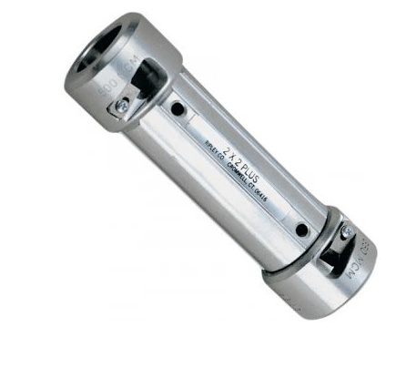
Utility Tool from Ripley offer two by two and four by four cable strippers with bushings. The bushings on each side are specifically designed for the conductor sizes you need. “Take about a twelve to 14 inch cut of all those sizes, and send them off to Ripley tools to get your specifically sized bushing.”
 |
 |
“To use these tools, just run it down to your spot, I have my hand as a stopper. Perfect cut. No scoring. Safe. Good to go.”

For those that need more adjustability on the system, the WS 71 and WS 72 Series provides mid span. Just tighten it down and again, run it right down. If you want to take the WS 71 and 72 and make them into one tool, take the US07-7000.
This is new tool from Ripley is capable of doing end strips and also your midspan strips all in one tool. “We used to have two tools for your chamfering. Now we have one tool.”
We also have a US10 7000 which performs a 30 degree chamfer, and then we have a US10 7001 which performs a 45 degree chamfer. See below for further product specification.
US07 Series
Adjustable 600-1000V Secondary Cable Stripper
Introducing the new US07 Adjustable Cable Stripper that quickly and easily end strips or midspan strips cable insulation with no conductor damage on 8 to 1000 kcmil secondary cables. The tool utilizes a size adjustment clamping system to swiftly adjust and lock onto the insulation. Its compact, low friction, thermoplastic, impact-resistant polymer v-jaw and body provides a stable and precise clamping platform in any space.
- Equipped with safe, recessed blade to prevent potential injury & blade damage
- Quickly adjusts to suit THHN, XHHW & USE secondary cables with 0.3″ to 1.375″ (7.6 mm to 35 mm) cable diameters, eliminating the need for bushings
- Easily adjusts with detent actuated knob & fine adjustment knob to match insulation thickness for fast stripping without conductor damage
- Features a replaceable, machined & ground tool steel blade
- Combines the end & mid-span strip performance of the UtilityTool® WS 71 & WS 72 with added features, stability & cable sizes
- Durable bronze bushings provides longevity
US10 Series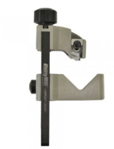
URD Cable Insulation Chamfering Tool
The new innovative US10 Cable Insulation Chamfering Tool utilizes a size adjustment clamping system to quickly and easily adjust and lock onto the insulation. Its compact, low friction, thermoplastic V-jaw construction and PTFE-coated aluminium frame provides a stable and precise clamping platform in any space.
- Easily adjusts to suit XLPE & EPR insulation materials on 0.5″ to 2.36″ (12.7 mm to 60 mm) cable diameters
- 30 degree or 45 degree angle bevel models perform with a factory-set chamfer depth of 0.075″ (1.905 mm), adjustable from 0″ to 0.150″ (0 mm to 3.81 mm); 15-35 kV
- Equipped with safe, recessed blade to prevent potential injury & blade damage
- Features a replaceable, machined & ground tool steel blade
See our complete range of Jointing Tools for the preparation and stripping of LV MV HV cable prior to the installation of joints, terminations and connectors.
LV, MV & HV JOINTING, EARTHING, SUBSTATION & ELECTRICAL EQPT
Thorne & Derrick International are specialist distributors of LV, MV & HV Cable Installation, Jointing, Duct Sealing, Substation & Electrical Equipment – servicing UK and global businesses involved in cable installations, cable jointing, substation, overhead line and electrical construction at LV, 11kV, 33kV and EHV.
THORNE & DERRICK Product Categories: Duct Seals | Cable Cleats | Cable Glands | Electrical Safety | Arc Flash Protection | Cable Jointing Tools | Cable Pulling | Earthing | Feeder Pillars | Cable Joints LV | Joints & Terminations MV HV
Sealing Cables For Cable Drum Storage | Part 3
November 22nd, 2021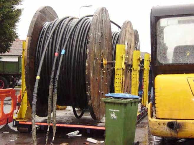
Sealing Cables
Stephen Harrison – Training & Technical Manager at Current Training Service Pty Ltd
In Part 1 and 2 of the series we discussed how to correctly seal cable ends and explored the different types of cable end caps which have been designed for pulling cables and storage.
Part 3 will explain about water getting into cables when storing cable drums outside.
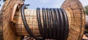
When cable drums are stored outdoors with end caps attached, the sun and other elements may cause the end cap to move and break the glue seals allowing moisture to migrate into the cable. If this happens, the cables are now in a poor state for installation as there may be some traces water in the cables prior to installation.
This is not an ideal situation.
The use of black sealant mastic and end caps will ensure the seal will not move or crack and water is less likely to penetrate the cables.
It’s important for your cables, which are being stored, to have the best chance of being in a pristine condition when you need to pull them in.
There are many “backyard” ways of sealing cables: PVC insulation tape wrapped around the ends of the cable, cloth and tape wrapped around the ends, plastic bags with tape wrapped around, and sometimes no end caps at all. The best way of sealing cables is with heat shrink or cold apply end caps and mastic.
To recap from Parts 1 & 2, when pulling cables and leaving the cables in pits etc, consider using triple end seals for added protection. When storing cable drums outdoors, consider using a drum storage for extra sealing and storage.
- Cable Pulling & Laying | Sealing Cables Whilst Installing | Part 1
- Cable End Caps | Cable Pulling & Storage | Part 2

Cable Pulling Cable Laying Equipment
Further Reading
Cable Pulling Calculation Example From Brugg Cables
Secure Spiking of Underground LV & HV Cables | Cable Spiking & Cutting Tools

Cable Pulling & Cable Laying Equipment


