Cable Pulling & Laying
January 7th, 2021

Cable Socks & Grips By Slingco | Offshore Cable Support & Strain Relief
Cable Socks For Saltwater
Slingco understands that choosing the right cable sock can be a challenge. There are key factors to consider when specifying cable socks, such as:
- How long the cable sock will be submerged. This could be 1 day, 1 month or longer
- The kind of environment, eg harsh conditions or rough terrain
- The effect saltwater has on a cable sock
- Whether a cable sock can still be used after exposure to saltwater
- How to choose the best cable sock for the application
Typically, where longer term saltwater exposure is involved, the choice is Aramid – specialist non-metallic socks.
Saltwater Test Results
Slingco have tested their cable socks by an independent leading, inspection, verification, testing and certification company. Here’s a sample from the test results of the effects of saltwater on steel socks.
Galvanised cable sock ZCS0307 after 40 days saltwater exposure

Galvanised cable sock ZCS0307
Extensive red rust corrosion covered the majority of the component. Red rust was observed from the first interval check, with white rust deposits on 2 sections.
Stainless steel cable sock ZCS1895 after 40 days exposure to saltwater

Stainless steel cable sock ZCS1895
Red rust corrosion was apparent on 60% of the sample. White rust deposits were observed on 5 sections, with the onset of degradation occurring after 1 week.
ARAMID SALTWATER TEST RESULTS
Aramid cable socks ZCS2816 after 40 days exposure to saltwater

Aramid cable sock ZCS2816
As you can see, there was no degradation or rusting throughout the test exposure, making these the most reliable cable socks for saltwater application.
Slingco have also undertaken extensive destruction tests on socks exposed to saltwater. To request a copy of the saltwater test report or the saltwater destruction report, please contact Thorne & Derrick.
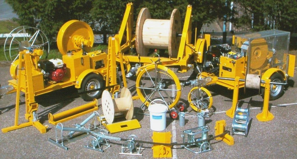
➡ Thorne & Derrick distribute the complete range of Cable Pulling Products to support safe installation of LV, MV & HV cables into underground ducts, conduits and trenches by cable pulling, laying and jointing contractors.

Cable Socks | Pulling Underground Cables & Stringing Overhead Conductors LV MV HV

CABLE SOCKS & PULLING PRODUCTS LV MV HV
Complete range of LV, MV and HV cable pulling products for installation and enabling cable jointing in trench or ducts including LV, 11kV/33kV medium voltage (MV), 66kV/132kV high voltage (HV) and EHV transmission and distribution cables up to 400kV.
➡ See Also Cable Laying, Installation & Support Products | MV HV Windfarm
December 22nd, 2020

Texcan provides electrical and electronic wire and cable products for power distribution, control, industrial automation, automotive, premise wiring, and networking applications.
Guest Article By Blair Sackney, Dec 2020
Texcan | Major Projects & Engineering Support
This article contains my technical opinion and is for general information purposes only.
Cable Pulling Large Cables
Calculations
It’s good design practice to perform a cable pull calculation for cable pulling and cable laying runs that might be difficult. Doing this early in the project allows for cable sizing and routing options that are often not available late in the game. Pull calcs are relatively easy to do but surprisingly few engineers or contractors use them.
The type of damage commonly created by excessive pulling forces will typically pass DC HiPot or VLF acceptance testing. Medium Voltage cables are especially susceptible to this kind of damage. It can result in partial discharge, leading to premature failures, commonly after 5 or 6 years of use.
While hand calculations can quickly spiral in complexity, there is software available to help simplify the process. Personally, I like Southwire’s Cable Pull Calculator, but a quick search will result in several other on-line options. Calculators are also available in most electrical modelling software.
The process involves inputting a few cable and pull set up parameters to verify that pulling forces will not result in cable damage. These parameters include gauge size, the number of conductors, cable OD and weight, raceway type and size, and each pull segment.
Performing more pull calcs and comparing them to real site experiences will result in an improved ability to make accurate assumptions. Pull calcs are more an art than a science as the calculations involve a lot of big assumptions making many other parameter assumptions rounding figures.
Figure 1: Conveyor sheaves can significantly reduce sidewall bearing pressure if installed
Side wall bearing pressure (SWBP), the radial force imposed at the bends, is by far the most common limiting factor. Excessive SWBP, usually visible in flattened armour or stretched jackets, can result in insulation damage which decreases cable life.
Common misconceptions that have only minor effects on the resulting pull calculations:
Maximum Pulling Tension – For power cables, this is usually not a limitation as the basket grip or pulling equipment usually limit pulling tensions before the conductors.
Upsizing the Conduit – Although you must maintain code required maximum fill requirements, upsizing conduits doesn’t lower tensions or SWBP by much.
Incoming Tension Assumption – Don’t sweat +/- 25 lbs on incoming tension assumptions as that will be a rounding figure in the final pull. However, using a cable feeder to push the cable in access points can help.
What does help:
Advance Planning & Field Communication – Can the field handle the reel you are specifying? Can it be placed where your pull calculation starts? Is there room to lay down cable for hand pulls or refeeds?
Straighten Out the Run – The fewer bends, the better. After two 90ᵒ bends, SWBP rises quickly.
Reduce run lengths – This reduces pulling tensions.
Bigger Conduit Sweeps and Sheaves – This makes a big difference to the SWBP. You should ensure that the cable minimum bend radius limitations are respected. That big 24” OD sheave is probably too small!
Tighter Coefficient of Friction (COF) Assumption – This parameter makes a huge difference in the final numbers. 0.35 is a common COF number for most common PVC jacketed industrial cables or regular building wire pulled through existing conduits. For a new installation with a good lubrication plan and experienced installation crew, 0.25 could be a more aggressive number. Southwire uses 0.15 for their no lube building wire products in PVC conduit.
Pull Boxes / Assist Tuggers – Add pull boxes to break the pull up into sections (pull out through the manhole and refeed back in). If the cables can be accessed in the middle of the run somewhere, properly set-up assist tuggers can also break up the run.
Reverse the Pulling Direction – Pull calculations are directional.
Use Equipment or Cable Products that Reduce COF – No lube cable, hydrophobic pulling ropes, Southwire SIM reels, cable tray rollers, etc., …
The final few bends might be hand pulled, reducing the need to include those sections in the cable pulling calculation. Be careful not to overbend the cable during these manual pulling steps.
Cable pull calculations can save a lot of field issues and help ensure a long, trouble-free service life of your big cable runs. A little extra effort upfront can save a lot of trouble down the road.
 THORNE & DERRICK
Cable Pulling Equipment
Thorne & Derrick distribute an extensive range of Cable Pulling & Laying Equipment to enable the safe installation of fibre and copper cables within the telecommunications industry. Safely installed cables reduces operational and maintenance requirements to the network and reduced service interruption to telecom cables, wires, ducts, cabinets and exchanges – products include cable spiking tools, conduit rods, cable lubricant, cable socks and cable rollers.
December 22nd, 2020

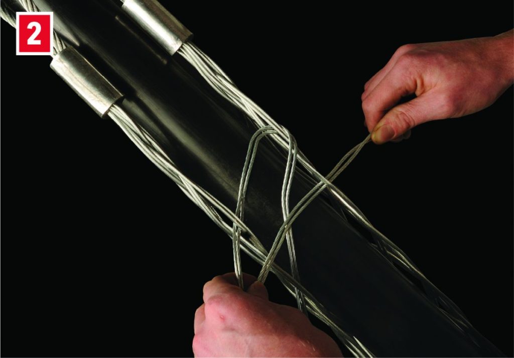
Reposition or support connected cable with lace up cable socks
Lace Up Cable socks
How do you pull cable or pipe when the exposed end is not available? How can you add support to a wire or conductor that is already connected? How do you take slack out of cable without disconnecting it?
A great way is to use a Slingco lace-up or rod-closing sock.
You can pull or support cable, wire or pipe at any point quickly and easily with a lace-up or rod-closing cable sock from Slingco.
Lace-up cable socks are an excellent support and pulling solution when the end of the cable or wire is not available, or for when a connection is already made but added support is needed. A lace-up cable sock can add support or pull conductor anywhere along the wire.
If you need to remove some slack from a LV MV HV cable that is in place, just use a lace-up sock to grab the cable and provide pulling leverage.
Lacing up a sock is safe, easy and quick. Slingco offers open weave cable socks in lace-up or rod-closing styles for a wide variety of cable ranges and strengths.
➡ Thorne & Derrick distribute the complete range of Cable Pulling Products to support safe installation of LV, MV & HV cables into underground ducts, conduits and trenches by cable pulling, laying and jointing contractors.
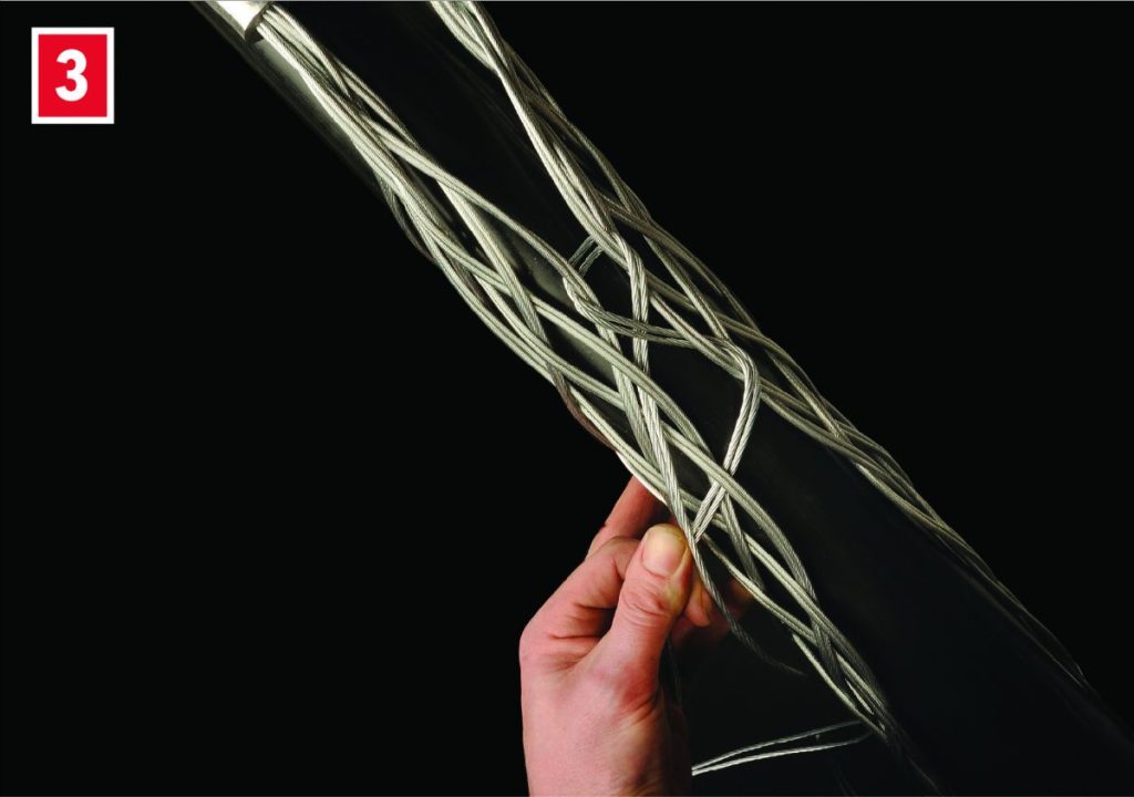
Simple instructions for installing a lace-up Cable sock
| STEP 1
Start the lacing from the ‘eye’ end or anchoring end of the cable sock. |
 |
| STEP 2
Thread the lace through the first two loops of the split and pull through until the laces are centred at this point. |
 |
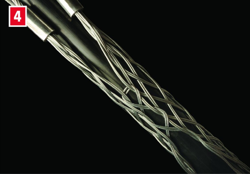
| STEP 3
Don’t pull the lace too tight at this stage. Leave a space between adjoining loops roughly equal to the width of one diamond of the mesh. |
 |
| STEP 4
Continue down the length of the cable sock. Try to maintain equal tension and equal spacing throughout as this leads to a more stable and equal sock. |
 |
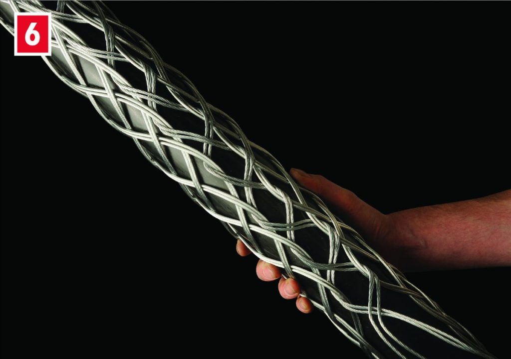
| STEP 5
As you continue down the length, pull the open sides of the cable sock as wide apart as required. |
 |
| STEP 6
Try to achieve an even and neat lace-up as this assists with the strength of the sock when pulling. |
 |
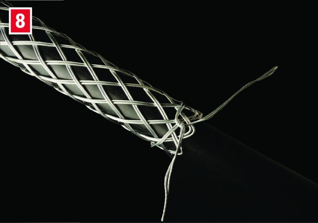
| STEP 7
Finally, tie the ends of the lace once or twice round the end of the cable sock twisting the ends together securely. Excess lace can be cut off. |
 |
| STEP 8
Add any additional support as required – banding is recommended. The Slingco cable sock is now ready to use. |
 |
PLEASE NOTE: The images shown here use double weave cable socks. When lacing single weave cable socks please use single wire lace; use double-laced for double weave cable socks; and use triple-laced for triple weave cable socks.
Cable Socks | Pulling Underground Cables & Stringing Overhead Conductors LV MV HV
CABLE SOCKS & PULLING PRODUCTS LV MV HV
Complete range of LV, MV and HV cable pulling products for installation and enabling cable jointing in trench or ducts including LV, 11kV/33kV medium voltage (MV), 66kV/132kV high voltage (HV) and EHV transmission and distribution cables up to 400kV.
➡ See Also Cable Laying, Installation & Support Products | MV HV Windfarm
December 22nd, 2020

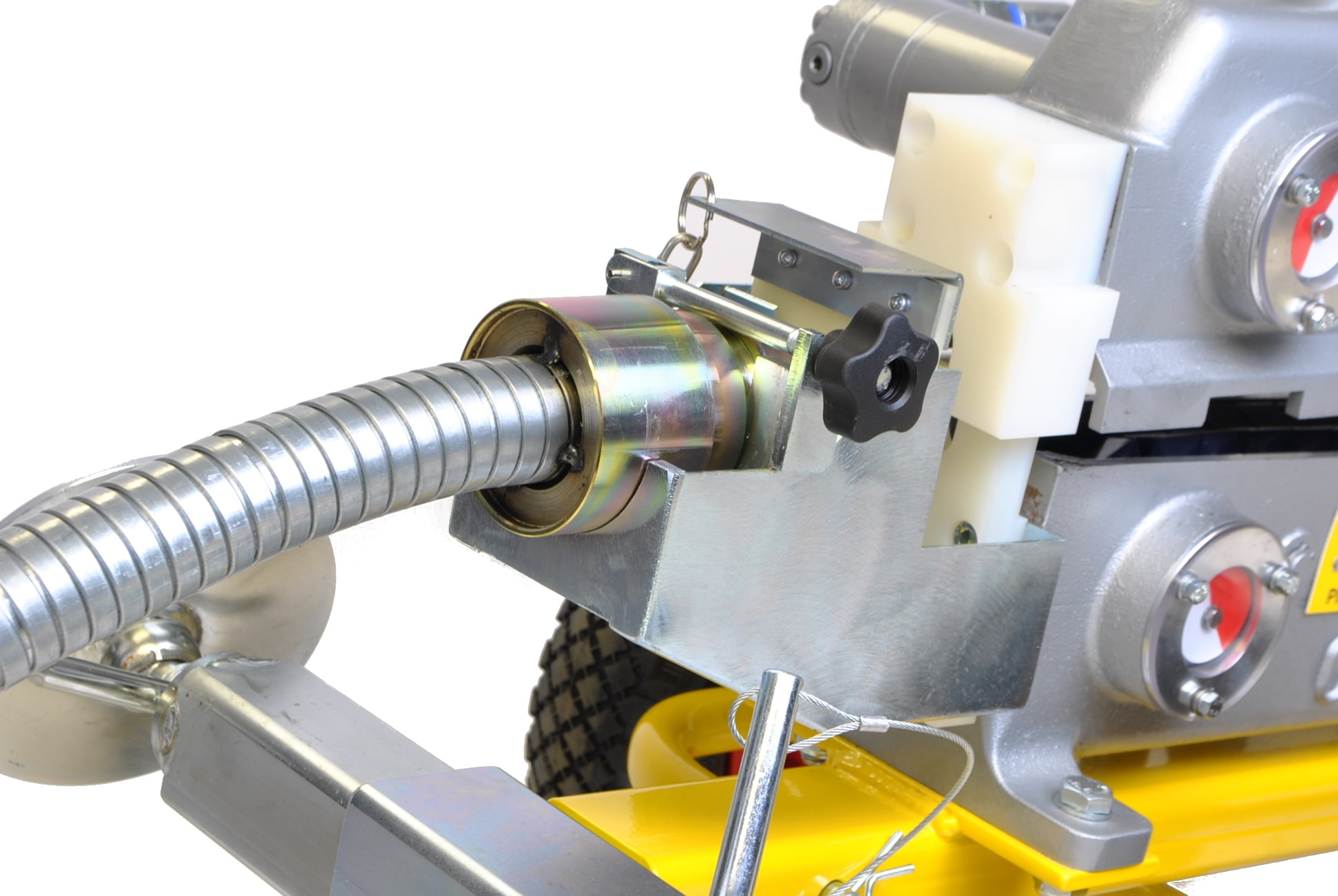
Duct Rod Pushers – contact us for a quotation or further information
Duct Rod Pushers
The CBS duct rod pushers are designed to assist in conduit and duct rodding operations.
Duct rod pushing equipment makes placing pulling lines or fibre cables into old or occupied conduits much easier and requires fewer operators.
The duct rod pushers are mounted on sturdy, anti corrosion treated tubular steel frame, and fitted with gel filled puncture proof tyres, with hydraulic controls mounted on the frame for ease of transportation. The rod pushers are fitted with a tilting extendable boom, and chamber clamp for use in underground structures.
Features
- Spring loaded self-centring fail safe operating lever.
- Measuring counter with reset lever.
- Front boom extending to 1 metre with angle facility dropping into underground chamber.
- Extendable chamber clamp for attaching to sidewalls. Range 400 – 800mm.
- Angle of operation 0-45º.
- Duct rod pushers feature integral lifting eye.
- Split pusher body which lifts and rotates to allow removal of duct rod.
- Anti crush control to prevent damage to rod.
- Disc spring controlled screw clamp to engage drive belts onto the rod.
- Cast aluminium body.
- Moulded profiled drive belts.

Contact Thorne & Derrick for competitive prices and delivery on the complete range of Duct Rods & Pushers for cable pulling applications.
Duct Rod Pushers
Specification: C-1270-0001-04-BT
| CBS Order Code |
C-1270-0001-04-BT |
| Product Description |
Duct Rod Pusher – 50cc motors |
| Diameter Range |
14mm |
| Installation speed |
0-30m/min* |
| Pushing/Pulling capacity |
220kgs at 60bar |
| Length |
1050mm |
| Width |
700mm |
| Height |
760mm |
| Weight |
53kg |
| * When used with the CBS C-1203-F power pack |
 ➡ T&D offer the complete range of CBS Cable Blowing Machines for FTTH FTTP fibre optic blowing.
- CBS Tornado Plus Cable Blowing Machine For Fibre Optic Cable Installations
- CBS Tornado Micro Tube Blowing Machine For Fibre Optic Cable Installations
- CBS BREEZE Cable Blowing Machine For Fibre Optic Cable Installations
- JetStream Cable Blowing Machine For Fibre Optic Cable Installations
- See also Fibre Optic Cable Pulling Lubricant

CBS Tornado Plus Cable Blowing Machine

Cable Pulling Equipment
Thorne & Derrick distribute an extensive range of Cable Pulling & Laying Equipment to enable the safe installation of fibre and copper cables within the telecommunications industry. Safely installed cables reduces operational and maintenance requirements to the network and reduced service interruption to telecom cables, wires, ducts, cabinets and exchanges – products include cable spiking tools, conduit rods, cable lubricant, cable socks and rollers.
October 28th, 2020

MULETAPE Calculator | selecting the right tape for the pulling of cables
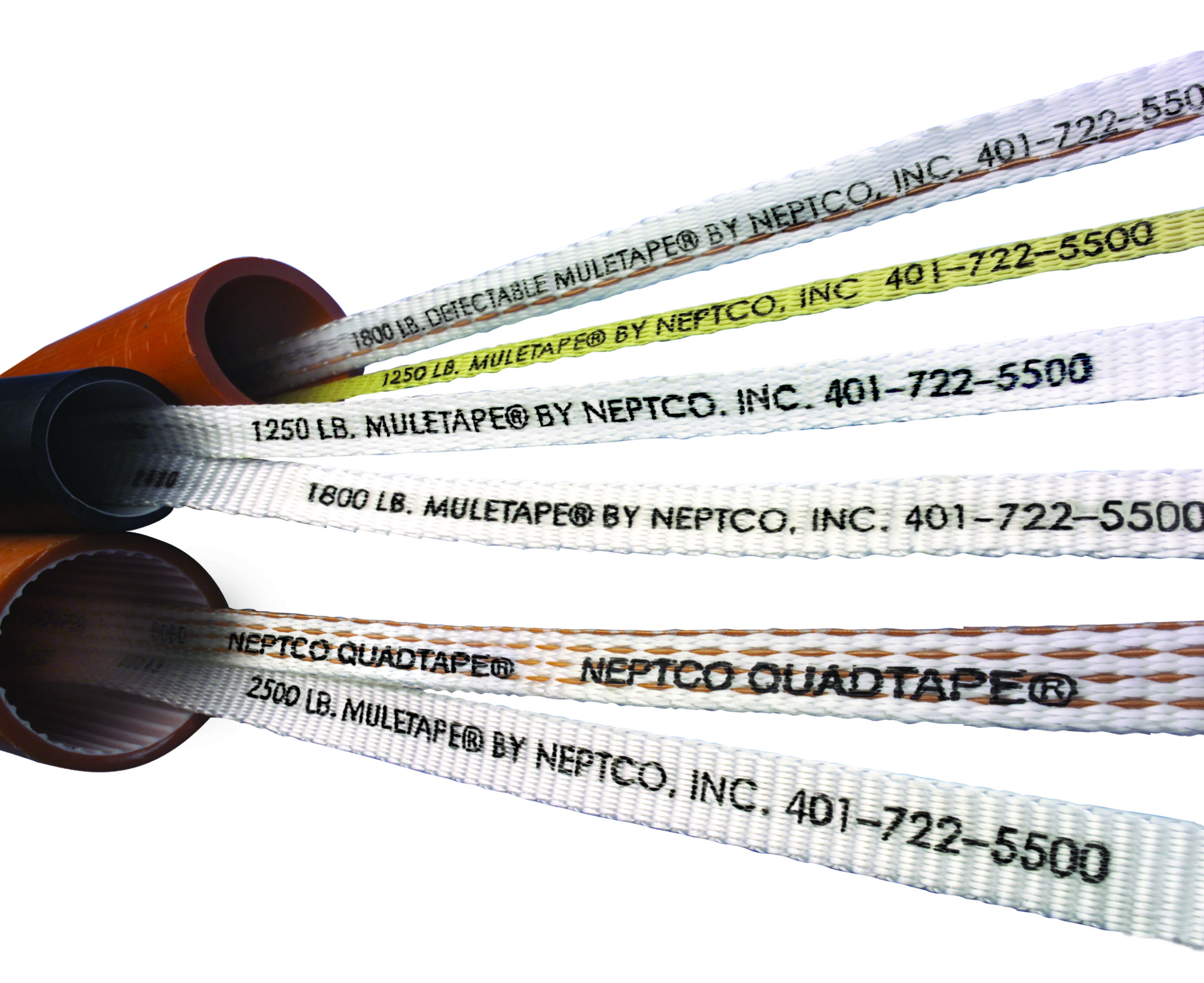
Muletape
NEPTCO is a global leader in the manufacturing of materials used for the Detection & Pulling of Cables, including MULETAPE, for a wide variety of commercial and industrial applications. This Blog demonstrates how the correct tape for pulling cables can be selected, with the MULETAPE calculator.

MULETAPE is a unique pull tape designed to reduce damage to the underground plant – resulting in improved efficiency, and enhanced worker safety.
To see the benefits of using MULETAPE over traditional cable pulling methods, see our Blog: MULETAPE V ROPE
NEPTCO tapes, distributed by Thorne & Derrick, are manufactured with a low stretch polyester material that distributes heat across its wide, flat profile. This improves efficiency and prevents “snap back”, which occurs when a rope under high tension elongates and either breaks or snaps back; often injuring the installer.
A variety of reel lengths of the cable pulling tape is available to suit any installation. Available in a variety of strengths (up to 6,000 lbs or 2727 kg) which enables extensive application use.
MULETAPE pulling tape for wires and cables is a laboratory and field tested for strength, temperature and chemical resistance, low elongation, low coefficient of friction (slips easily even on long pulls), and long life.
MULETAPE CALCULATOR
Cable weight is the biggest influence in MULETAPE recommendations, followed by the number of bends and finally the conduit size.
Pulling tension is a cumulative calculation with each bend in the conduit run contributing to more drag as the pull goes on. It is important to consult the cable manufacturer’s specifications for the maximum pulling tension before installing the cable. If pulling tensions are more than the maximum recommended limit, an intermediate pull box or manhole will need to be placed. MULETAPE is offered in tensile strengths varying from 400 to 6000 lbs.
Pulling forces vary depending on fill ratio, terrain and underground architecture; actual field conditions should be considered. The tension calculator below is intended to be used as a guide.
POINT TO POINT LOOK UP TABLE – FOR BEND ANGLE, DEGREES
| Bend Angle, Degrees |
|
0 |
15 |
30 |
45 |
60 |
76 |
90 |
| Single Cable |
1 |
1.11 |
1.23 |
1.37 |
1.52 |
1.69 |
1.87 |
| Multiple Cable |
1 |
1.14 |
1.3 |
1.48 |
1.69 |
1.92 |
2.19 |
It should be noted that pulling tension can vary on the same pull. It is important to determine the starting point that will exert less strain on the cable. Usually, lower tension can be achieved by placing the cable reel closer to the shortest 90-degree bend. It might be helpful to make a sketch of the conduit run, showing bends.
The following is an example of a 460-foot pull of a 3 single conductor #2 15kV in 4” PVC conduit. The cable weighs 1.85 lbs. per foot. Please note the tension changes depending on the starting point of the pull.
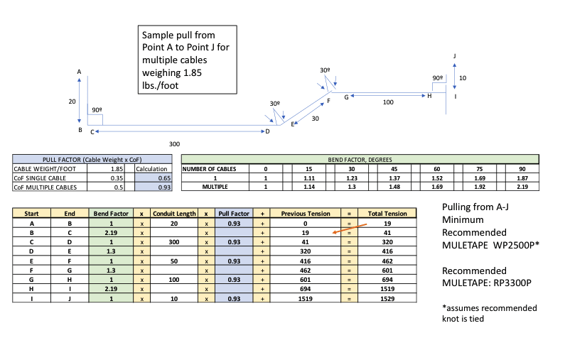
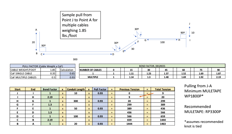
As you can see from the examples above, pulling from point J to A results in a lower overall pulling tension; consequently, assuming the recommended knot is tied, a lighter duty MULETAPE can be used to complete the job.
Muletape Calculator Instructions
To apply these formulas in your cable pulling application, follow these steps:
- Determine the weight per foot of your cable.
- Multiply the weight by the coefficient of friction for either single cable or multiple cables to determine the pull factor.
- Sketch the pull and determine the lengths between bends.
- Multiply the bend factor by the length of conduit.
- Multiply the result by the pull factor.
- Add the resulting tension to the next length of conduit and repeat steps 2-5.
- Repeat step 6 until the last point results in the cable exit.
- Determine if the tension is lower if the cable is pulled from the opposite end by repeating the same steps from the other end.
MULEKNOT + MULETAPE = a winning combination!
The weakest point of MULETAPE is the knot, and a poor knot can severely impact the tensile performance of the pulling tape. We recommend a MULEKNOT™ or blood knot, which can provide 80% of the rated tensile strength of MULETAPE.
The MULEKNOT is designed to maximize the pulling strength of NEPTCO MULETAPE, while providing a simple, reliable method of splicing lengths of tape in the field. Using the MULEKNOT instead of a traditional bowline knot can greatly increase the pulling strength of the splice and/or connection.
For more information on the MULEKNOT, please see the attached data sheet.
Further Reading

CABLE PULLING EQUIPMENT
Thorne & Derrick International are the UK’s leading stockist and supplier of Cable Pulling & Cable Laying Equipment for the installation of underground cables and overhead lines up to 400kV – the products support cable pulling teams to install LV MV HV cables into trench, cable duct, risers and all forms of cable containment.