

Earthing
Safer Exothermic Welding With Apliweld Remote Electronic Ignition & Bluetooth Starter
October 8th, 2018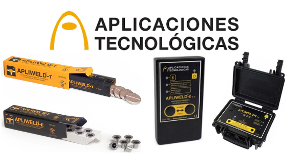
-
uploaded by Chris Dodds - Thorne & Derrick Sales & Marketing Manager
Exothermic Welding
Today, Thorne & Derrick welcomed Jason Leatherland (UK Manager at Aplicaciones Tecnológicas (AT3W) Lightning Protection & Earthing) to their UK office to learn more about their innovative Exothermic Welding System – Apliweld Secure+ is the safest + most efficient system for establishing Exothermically Welded Connections on substation earthing projects in the UK DNO, Power Transmission & Distribution and ICP sectors.
So What’s New?
The market-leading modern technology with remote electronic activation using Bluetooth replaces the conventional exothermic welding system dependent upon a manually applied spark using a Flint Gun for the welding and bonding connection of copper conductors including copper earth rods, cables and earth tapes.
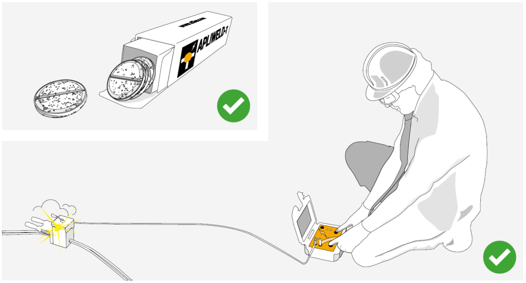
Apliweld Secure+ replaces traditional welding powders (and all of their size variations) with a welding tablet compound activated remotely, by up to a safe 5 metre distance, from the controlled explosion location – the electronic starter reduces risk of burns injuries and improves operational Health & Safety.
Apliweld Secure+ is accepted or in the approval process for use at National Grid, Northern Powergrid, Western Power Distribution, Scottish Power Energy Networks (SPEN) and Electricity North West (ENWL).
AT3W are a Spanish manufacturer and supplier of Earthing & Lightning Protection products and solutions – their unique selling point is their dedication to innovation and R&D within the industry along with their complete product/solution portfolio.
What is Exothermic Welding?
Apliweld exothermic welding is a process that achieves the molecular bonding among two or more metallic conductors by a chemical reaction. This molecular bonding improves mechanical, electrical and anti-corrosion properties compared with any mechanical or clamped connection. Apliweld exothermic welding is the most efficient method to achieve permanent, reliable and high conductivity connections for any LV MV HV substation or installation requiring an earthing system.
Secure Exothermic Welding At Safe Working Distance
APLIWELD Secure+ Exothermic Welding SYstem
Apliweld Secure+ is the most innovative, efficient and safest method for making electrical earthing connections with exothermic welding and comprises the of following components:
| APLIWELD Part Reference | Product Image | Product Description | Technical Characteristics | Benefits |
| APLIWELD-T Exothermic Welding Tablets |  |
Innovational tablet utilising only 2 sizes to produce all exothermic welded joints. Two references AT-020N, the most common one (valid for 90% of connections )and AT-021N larger size tablets, for use on larger joints. | • Reference: AT-020N • Tablet dimensions: ø 43 mm. • Units per pack: 20 tablets • Packaging dimen.: 52x52x220 mm. • Total weight: 900 gr.• Reference: AT-021N • Tablet dimensions: ø 55 mm. • Units per pack: 20 tablets • Packaging dimen.: 66x66x200 mm. • Total weight: 2.000 grams |
• Compact and easy to use • Reduces stock costs • Improves welding process times • Increases equipment life-time • Both electronic and powder starters can be employed |
| APLIWELD-E Electronic Starter |  |
Not flammable. Electronic starters only ignite through the power supplied by the ignition device. | • Reference: AT-010N • Dimensions: 26 mm. ø24 mm. • Units per pack: 10 • Packaging dimen.: 125x105x40 mm. • Total weight: 87 grams • Time of reaction: < 10 sec. • Material: not flammable |
• Its safety handle and storage features reduce labour risks • Safe & easy setup |
| APLIWELD®-E Electronic Ignition/Starter Device |
 |
Ignition box enables controlled and remote electronic ignition of exothermic welding connections in a quick and safe way. Includes: ignition unit (AT-096N), cable (AT-098N), 5 crocodile clips (AT-099N), battery charger and bag carrier. | • Reference: AT-100N • Power supply: • Lead acid battery 6V 7Ah • DC Voltage: 6V DC • Battery charge: 12-36V DC 500 mA • Battery life: more than 100 joints • Battery charging time: 10 hours • Dimensions: 216x180x102 mm • Weight: 2300 grams |
• Remote control ignition reduces labor risks. |
Apliweld Secure +
Benefits
- Eliminates the need for numerous variety of exothermic welding size powders
- Single welding compound reference for every welded earthing joint or connection
- Reduction of stock volume : cost ratio
- No shelf life and is non flammable
- Much safer to use – electronic ignition unit / Bluetooth starter as opposed to flint gun
- Minimises user error – every mould engraved with components/materials to be used
- Can be used in windy conditions (zero powder spillage)
- Highest possible ignition rates – less material failure
- Reduced wastage from cartons, cups etc
- Easy to use, reduces costs in labour and training
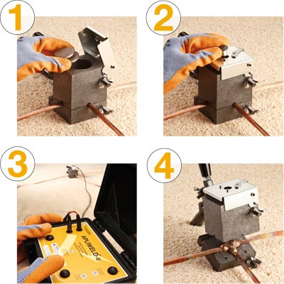
How to use Apliweld Secure+ Components

| AT3W Part Number | Product Image | Product Description | Stage | Process |
| APLIWELD-T |  |
Welding compound in tablets | 1. Insert the tablets APLIWELD-T |  |
| APLIWELD-E | 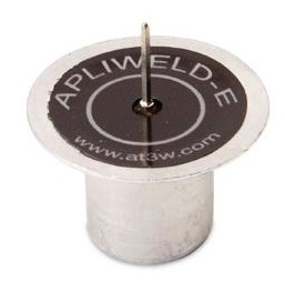 |
Electronic starter | 2. Place and connect the electronic starter APLIWELD-E |  |
| APLIWELD-E | 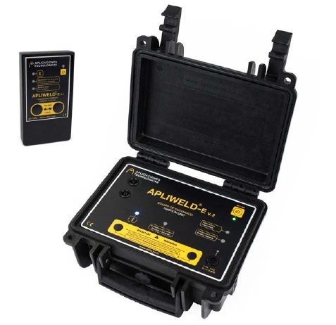 |
Electronic starting device | 3. Press both push-buttons on ignition device or Bluetooth remote at the same time |  |
| Exothermic Weld |  |
Graphite mould | 4. Remove the completed joint from the graphite mould |  |
Specific Exothermic Weld Mould Video
The following video shows the operating procedure for specific mould Apliweld Secure ensuring the process of exothermic welding is efficient.
Step 1 – Clean and remove any impurities from the mould or conductors
Step 2 – Heat the mould to 120°C before welding or when the mould is not hot enough
Step 3 – Fit the copper earth conductors into the mould and close the handle clamps
Step 4 – Set the proper number of tablets (see engraved on mould surface) in the crucible
Step 5 – Close the mould cover and place the electronic starter. Fix in position using lever
Step 6 – Open the Ignition Unit and connect the plugs. Connect the other side of the cable to the lateral part of the mould. Fix the clamp to the spike of the Electronic Starter
Step 7 – Keep away from the mould and switch on the Ignition Unit. Press both ignition buttons simultaneously until the exothermic welding process starts
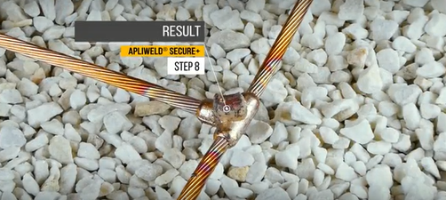
Step 8 – Result is below image of an exothermically welded connection
Apliweld Secure – reliable electrical grounding, bonding and connection products for medium/high voltage substation earthing.

Contacts us NOW to arrange a DEMO or to discuss your Exothermic Welding requirements
Innovation, Reduction In Storage Costs & Increased Safety
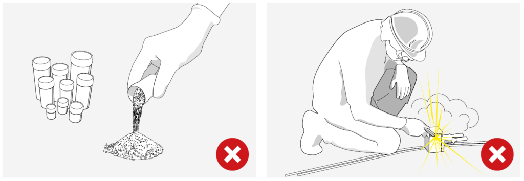
Traditionally, exothermic welding required the user to be provided with multiple cartridges with different welding powder weights for establishing various connections.
Once the conductors were inserted in the graphite mould the welding compound and the reactive powder (usually a flammable compound) were poured into the crucible. Then a flint gun applied manually to the starting powder at arm’s length produced a spark triggering the exothermic reaction.
Apliweld Secure+ utilises exothermic welding tablets NOT powders which are activated at safe working distance to suit all conductor combinations and configurations. The exothermically welded earthing connections are engineered to provide a permanent, molecular bond that will resist corrosion and loosening.
AT3W & Thorne & Derrick
Thorne & Derrick will be working with AT3W to introduce and develop specifications and business for the Apliweld Secure+ exothermic welding system.
Jason Leatherland comments, “having worked successfully together with Thorne & Derrick in the past, I was keen to demonstrate and discuss this product system with them as I knew they would be best suited to showcase the system, and in particular, its increased health and safety benefits, to the most relevant sectors in order to increase the users efficiency and reduce the potential of site accidents from exothermic welding.”
Jonny Hewitt (T&D UK Power Team) added, “working with the UK DNO’s and their preferred ICP’s we look forward to further developing relationships and presenting the exothermic welding system to existing and new clients. We will be working closely with AT3W to introduce the product to market and improve worker and site safety in the utility industry.”
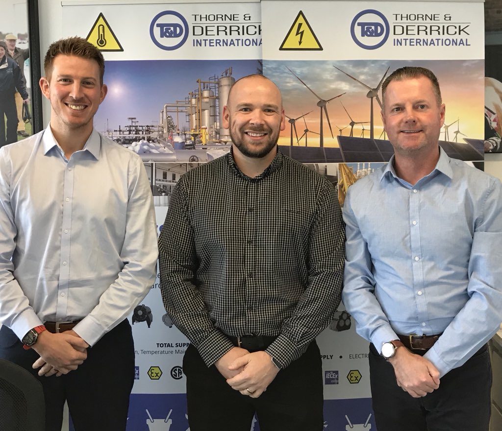
Pictured: Jonny Hewitt (T&D) with Jason Leatherland and Chris Dodds (T&D).
💡 HV Earthing & Lightning Protection Training Courses go to ➡ Online Training Resource provided by Ian Griffiths, Principal Engineer at GreyMatters. Ian is an Earthing & Lightning Consultant of 27 years, one of the top 1% UKAS accredited CDEGS consultants and professional advisor to international utility companies, data centre and infrastructure developers. See our Blog to learn more about GreyMatters and High Voltage Earthing.
LV MV HV Cable Accessories & Substation Electrical Equipment
Thorne & Derrick are Specialist Distributors of leading manufacturers of Cable Accessories, Substation Earthing, Jointing & Installation Equipment.
LV MV HV cable accessories from stock used to joint, terminate, connect, cleat and gland power cables to air and gas insulated substations, transformers, switchgear and overhead line networks.
LV 600/1000V ◊ MV 11kV 33kV ◊ HV 66kV 132kV
 |
 |
 |
 |
 |
 |
 |
 |
 |
 |
Lightning Protection Earthing Systems – Type A,B & Foundation Earth Electrodes
July 10th, 2018
-
uploaded by - Chris Dodds (Sales & Marketing Manager Thorne & Derrick)
The following information has been provided courtesy of AN Wallis, leading UK manufacturers of Earthing & Lightning Protection Systems.
In general the Lightning Protection System (LPS) system should:
- Be an integrated system for lightning protection, power systems and telecoms systems
- Have a low overall resistance of 10 ohm’s or less
- Have an even spread of readings across all the individual earth electrode terminations to ensure as far as possible the current is evenly distributed
- Have a high resistance to corrosion
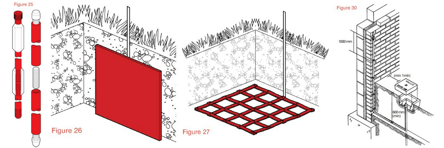
Lightning protection and earthing equipment is usually made up of earth rods either copperbonded, solid copper or stainless steel (figure 25) – also forming the earthing system are copper earth plates (figure 26), copper lattice earth mats (figure 27) or 25 x 3mm copper earth tapes.

Driven earth rods manufactured from solid copper and bonded with copper are available from stock – contact Thorne & Derrick
There are three types of LPS Earthing systems types A, B and Foundation Earth Electrodes
Type A – The conventional LPS Earthing system using
vertical or horizontal electrodes such as
copperbond Earth rods or copper tape
Type B – The ring electrode sited around the periphery of the structure
Foundation Earth Electrodes
The foundation electrode system installing the conductors in the concrete foundations of the structure.
Type A Earthing Arrangement
This is the conventional type of LPS Earthing System where earthing rods are used to form the earth electrode and usually each down conductor, such as copper earthing tapes, are connected to an earth rod.
The type A earth termination arrangement is suitable for low structures (below 20 metres in height) or an LPS with rods or stretched wires. For an isolated LPS the British Standard BS EN 62305 recommends a type B earthing arrangement where the structure is housing extensive electronic systems.
The type A arrangement uses vertical or horizontal earth electrodes. Practically it uses both connected to each down conductor, installed outside the structure (below the foundation) to be protected and housed in a plastic or concrete pit for ease of inspection (figure 30).
Lightning Protection – Copper Earthing Equipment
The minimum number of electrodes is 2.5 metres, regardless of the perimeter of the structure/class of LPS.
The minimum length of each earth electrode at the base of each down-conductor is specified in BS EN 62305 and the table below.

Minimum length l¹ of each earth electrode according to class of LPS
It is 11 for horizontal electrodes – usually copper tapes.
Or
0.511 for vertical copperbonded rods or solid copper rods. Or
>11 in the case of a lattice mat measuring the total length of the conductor in the earth mat.
Or
If copper plates are to be used the surface area of the plate should be at least equal to either.
The surface area of the length of earthing conductor that would need to be used to satisfy the requirement for a vertical electrode 0.511.
Or
The surface area of the length of earthing conductor that would need to be used to satisfy the requirement for a lattice mat electrode 11.
Or
If using vertical and horizontal electrodes, the individual earthing electrode lengths should follow the 0.511 and 11 principle respectively.
Type A earth electrodes should be installed so that the top of the earth rod is 0.5 m below the surface, this distance is to reduce the effects of step potential at ground level.
The earth rod should be housed in an inspection pit, commonly concrete or plastic for ease of inspection and registering the location during and after installation figure 30.

Full range of copper earth tapes available from stock in range of widths and thicknesses.
Type B Earthing Arrangement
The type B Earthing arrangement is most suitable for:
- Structures built on rocky ground
- Structures housing sensitive electronics/equipment
- Large structures
The type B earthing is recommended as either a ring conductor outside the perimeter of the structure which it’s recommended should be in contact with the soil for at least 80% of its total length.
The alternative is to use a foundation earth electrode which can be in a mesh form.
It is recommended that the type B earthing network whichever method is chosen should be integrated as a meshed network buried to a minimum depth of 5 rats.
The reinforced concrete floor slab can be used around the structure.
If the required resistance cannot be achieved by this method the vertical or radial earthing electrodes can be added to the network.
For ease of testing after installation an inspection pit with an earth bar should be installed where the legs of the ring and conductor routing onto the ring from the each test clamps join (figure 31).

Any internal down conductors should be connected to the internal foundation using a test clamp for ease of maintenance.
Foundation Earth Electrodes
Once all the services are connected its unlikely the installer will be able to measure the earthing resistance of the foundation earth in isolation.
The use of the foundation as an earth electrode is allowable only where the reinforcement network is below any insulating or waterproof membrane.
Where a foundation is used as an earth-termination the reinforcing bars must be clamped or welded together to ensure electrical continuity.
Alternatively an additional meshed network of conductors can be installed to ensure continuity. The additional network should be connected to the reinforcing bars by clamps or welded joints every 20 m throughout the system.
The earthing system whether using reinforcing bars or additional conductors or a combination of both must be connected to every down conductor and internal steelwork.
Internal Lightning Protection System
The internal LPS is important to fully complete the installation to fulfil the requirements of BS EN 62305.
The main reason for installing an internal LPS is to avoid any dangerous sparking within the building.
The sparking is caused by current flow and the difference in potential between internal conductive components such as steelwork and the external LPS on the outside of the building or from the use of the internal steelwork as part of the LPS.
The earthing system whether using reinforcing bars or additional conductors or a combination of both must be connected to every down conductor and internal steelwork.

THORNE & DERRICK
T&D are Specialist Distributors to UK Distribution Network Operators (DNO’s), NERS Registered Service Providers, ICP’s and HV Jointing Contractors of an extensive range of LV, MV & HV Jointing, Earthing, Substation & Electrical Eqpt – this includes 11kV/33kV/66kV cable joints, terminations and connectors for both DNO and private network applications.
Contact our UK Power Team for competitive quotations, fast delivery from stock and technical support or training on all LV-HV products.
Key Product Categories: Duct Seals | Cable Cleats | Cable Glands | Electrical Safety | Arc Flash Protection | Cable Jointing Tools | Cable Pulling | Earthing | Feeder Pillars | Cable Joints LV | Joints & Terminations MV HV
BS EN 62305 – Earthing & Lightning Protection System Design
July 10th, 2018
-
uploaded by - Chris Dodds (Sales & Marketing Manager Thorne & Derrick)
Design of Lightning Protection System
The following information has been provided courtesy of AN Wallis, leading UK manufacturers of Earthing & Lightning Protection Systems.
The LPS (Lightning Protection System) is required to:
- Intercept the lightning strike (the air termination network)
- Conduct the lightning strike safely to ground (using down conductors, such as copper earth tapes)
- Disperse the strike safely into the earth (earthing)
- Whilst the structural protection is there to conduct a strike safely to earth this is normally combined with internal protection to prevent sparking within the structure ensuring all metallic services are at equipotential (bonding)
The designer of the LPS should ensure that:
- The safest path to earth is the LPS
- The risk of sparking whilst the strike is conducted safely to earth is minimised (separation distance/s)
- The risk of voltage differential whilst the strike is being dissipated in the ground safely is minimised (step & touch potentials)
The designer of the LPS has to gather all the relevant information to ensure the earthing system design is as safe as possible within any economic restraints:
- A designer may find it impractical to fully install the desired LPS
- A designer may not be able to justify the cost of providing the desired LPS
- A designer may consider using the metal roof or reinforcing bars within a building as the safest and most economic design
- A designer may consider extra bonding and surge protection devices are required to protect the internal space, especially if the space houses sensitive electronic equipment
- A designer may consider a building of such a high risk that additional measures are taken to ensure safety, possibly a flour factory or a building with a combustible roof, in these cases the LPS system may have to stand off the building
Contact Thorne & Derrick for largest UK stocks of copper earth tapes.
Criteria For The Protection Of Structures
The level of protection/Lightning Protection Level (LPL) applied to the structure is identified by the risk assessment.
Lightning Protection System (LPS) Level
- LPL I requires a Class I
- LPS LPL II requires a Class II
- LPS LPL III requires a Class III
- LPS LPL IV requires a Class IV LPS
Design of The LPS General Considerations
To help the earthing system designer, the threat of lightning to a structure or building can be defined in lightning protection zones requiring protection and the type of lightning strike likely to enter the building shown in Figure 2.
S1 – Strike directly to the structure
S2 – Strike on the ground near the structure
S3 – Strike to a service connected to the structure
S4 – Strike on the ground near a service connected to the structure

LPZ1 – The protected zone inside the building, the zone where current is limited by current sharing and SPD’s at the boundary (less the separation distance)
LPZ Oa – At risk from the full lightning strike and the full lightning electromagnetic field
LPZ Ob – Not at risk from a direct lightning strike considering the protected area through the rolling sphere but at risk from the full lightning electromagnetic impulse. (LEMP)
LPZ 2 – Protected zone with further dampened magnetic field
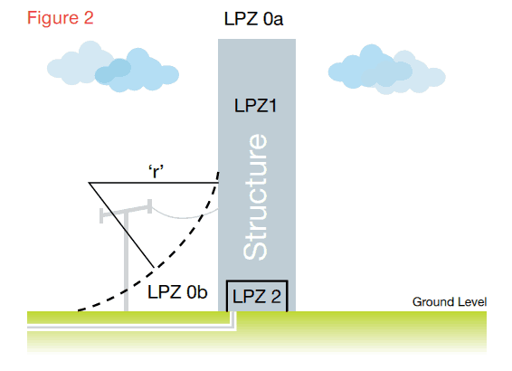
The LPS designer should ensure everything to be protected falls inside the LPZ Ob range in figure 2.
- The bonding measures employed need consideration at the design stage
- The earthing design should consider fully the step and touch potential risks
- The requirements for Surge Protection Devices (SPDs) on incoming mains and conductive services should be considered in accordance with the risk assessment carried out for the structure LPS requirements
- Where combustible wooden type materials are present a distance of 0.15 m should be maintained between the LPS conductors and the roof, for any other combustible surfaces a distance not less than 0.10 m is required
- Some structures will have reinforced sections with expansion joints, if the designer of the LPS considers electronic equipment within the building is at risk then bonding conductors should be provided across the joints to provide low-impedance potential equalization. The separation distance between the bonds should not be more than half the distance between the down conductors
- Natural components within/part of the structure such as the rebars can be made use of provided they will always remain an integral part of the structure conforming to the requirements below
Manufacturer by high conductivity and purity copper the range of earth tapes provide effective protection to buildings and substations
Using natural conductors as part of the LPS
The building’s natural components, metal roof, rebar, steelwork etc can be considered as part of the LPS provided they meet the minimum criteria shown in Table 1.
| Material for LPS levelI to IV | Prevents puncture, hot spots or ignition. minimum thickness (mm) (ta) requirement | Only for metal sheets where preventing puncture, hot spots or ignition is not important. minimum thickness (mm) requirement (tb) |
| Lead | 2.00 | |
| Stainless Steel | 4 | 0.50 |
| Titanium | 4 | 0.50 |
| Copper | 5 | 0.50 |
| Aluminium | 7 | 0.65 |
| Zinc | 0.70 |
The reinforcing bars within the concrete structure can be used as a natural component of the LPS provided they are electrically continuous by either welding or clamping the joints.
The re-bars are considered as electrically continuous provided that the major part of interconnections of vertical and horizontal bars are welded or otherwise securely connected by clamps conforming to BS EN 50164 standards.
The connecting rebar must overlap and be clamped using rebar clamps or welded to a minimum of 20 times the diameter of the rebar as shown in figure 3. (Welding to be done on either side of the rebars.)

Example of a rebar joined by clamps
To test the continuity of the reinforcing bars the resistance between the re-bar connection to the air termination network and the rebar connection to the earthing network should be measured, the resistance should not exceed 0.252, otherwise proprietary down conductors will be required.
In order to provide a connection to the rebar from outside the concrete a cast-in earth plate can be used as shown in figure 4, the earth point sits in the wall (or within an enclosure) providing a connection to the re-bar with a welded copper tail attached to the earth point and to the re-bar with propriety clamps.

Earth point sits in the wall providing a connection to the rebar
The designer of the structural LPS has 4 main criteria to consider:
- The roof termination system
- The down conductor configuration
- The Earth Termination network including equipotentialization and the risk of step and touch potential (equipotentialization on its own is not effective in reducing the risk against touch voltages)
- Bonding (creating a euipotential zone across all zones, Oa, Ob, Z1, Z2)
The diameter of the sphere depends on the class of LPS selected/determined.
| Class LPS | Sphere Radius |
| I | 20 |
| II | 30 |
| III | 45 |
| IV | 60 |

Complete range of earth bars with connection options and number of cable termination ways to provide effective common isolation point.
Methods Of Designing The Air Termination Network
1 – The rolling sphere
2 – The protective angle design
3 – The mesh design
The Rolling Sphere Method
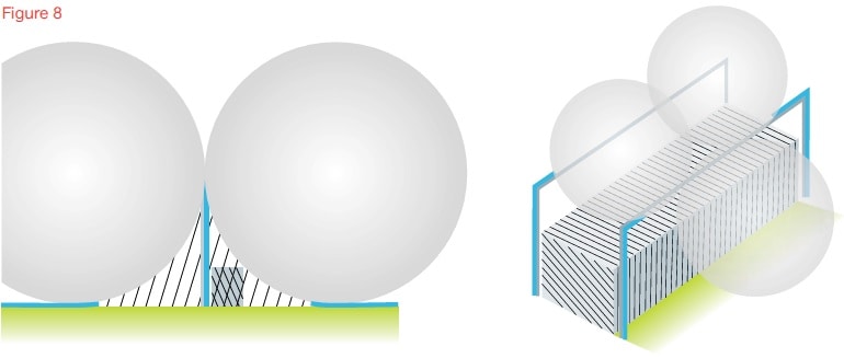
This method simply rolls a sphere around the building to be protected, wherever the sphere touches the building dictates where the protection measure is to be applied, where the sphere does not touch the building, this is accepted as a protected area, this method can be used to design the LPS on complex structures or where the LPS has to be isolated.
The rolling sphere method is especially relevant on complex structures with many different levels, this method easily identifies the protected space and where protection measures should be applied to the structure.

Examples of the air termination system using the rolling sphere technique
Designing The Lightning Protection System (LPS)
The Protective angle design
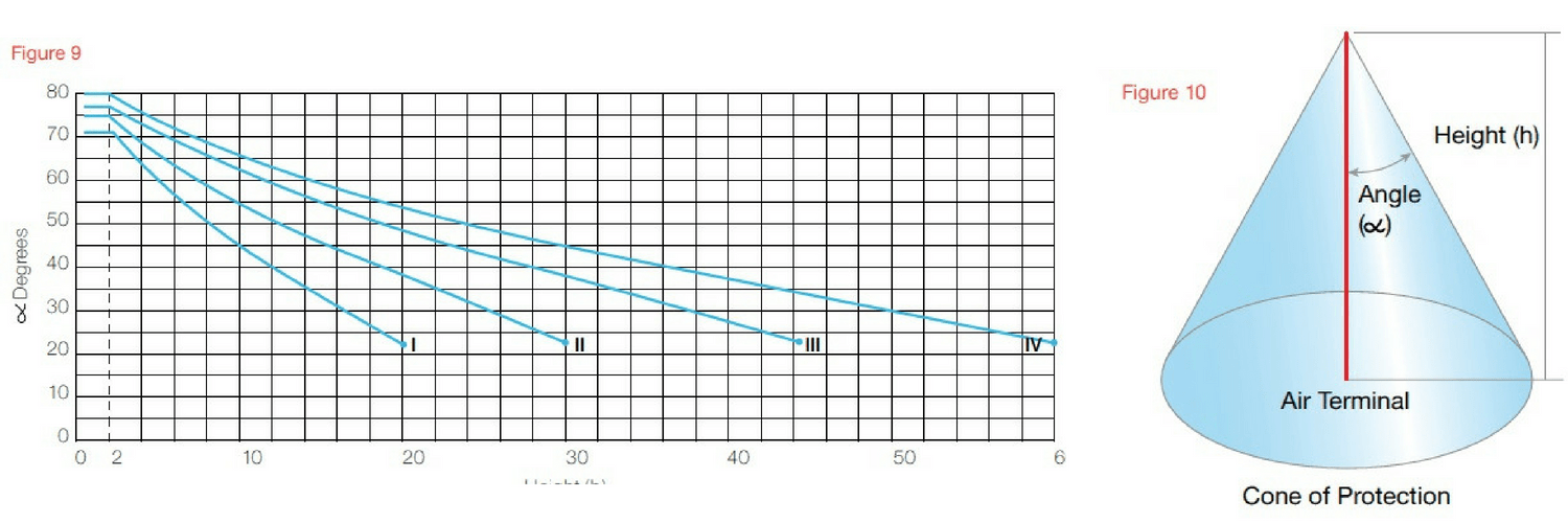
The Protective Angle method in figure 10 is only used on simple structures or for small sections of larger structures.
The Protective Angle design method cannot be used where the part of the structure/service to be protected is higher than the radius of the rolling sphere corresponding to the class of LPS.
The level of LPS dictates the angle of protection depending on the reference height, see figure 9.
This method of earthing system design is an alternative method based on the rolling sphere and is not offered to give a wider range of protection than the rolling sphere.
In figure 9 the height limits for designers are clear and correspond to the radius of the rolling sphere.
Protective Angle Design
The Mesh design
The most commonly used method, is usually employed where the structure is simple, a square or rectangular building or typical house or block of apartments with a sloping roof, the mesh method is for protection in zone OA.
The mesh design protects the whole area if conductors are positioned on the edge of the roof where the slope of the roof exceeds 1:10.

Protective angle design to protect free standing equipment on the roof of a building
On structures up to 60 metres in height, only consider applying an air termination system to the roof and provide protection to points, corners and edges of the structure. No lateral air termination is required regardless of the class of LPS.
On structures higher than 60 metres lateral air termination systems should be applied to the top 20% of the structure relevant to its class of LPS (or at least conforming to class IV LPS).
The mesh of earth conductors are installed on the roof, the earth conductor must be at the edge of the area to be protected and for metal items such as air conditioning units that protrude above the conductor, the protective angle design should be applied for protection.
The size of earth mesh required is defined by the level of LPS determined/selected
| LPS Class | Mesh Size (M) |
| I | 5 x 5 |
| II | 10 x 10 |
| III | 15 x 15 |
| IV | 20 x 20 |
THORNE & DERRICK
T&D are Specialist Distributors to UK Distribution Network Operators (DNO’s), NERS Registered Service Providers, ICP’s and HV Jointing Contractors of an extensive range of LV, MV & HV Jointing, Earthing, Substation & Electrical Eqpt – this includes 11kV/33kV/66kV cable joints, terminations and connectors for both DNO and private network applications.
Contact our UK Power Team for competitive quotations, fast delivery from stock and technical support or training on all LV-HV products.
Key Product Categories: Duct Seals | Cable Cleats | Cable Glands | Electrical Safety | Arc Flash Protection | Cable Jointing Tools | Cable Pulling | Earthing | Feeder Pillars | Cable Joints LV | Joints & Terminations MV HV
BS EN 62305 – Protection Against Lightning Strikes & Risk Management Notes
June 11th, 2018BS EN 62305

AN Wallis manufacture earth tapes from high conductivity copper to ensure LPS designs and installations conform to latest Britsh and International standards
-
Uploaded by Chris Dodds - Thorne & Derrick Sales & Marketing Manager
BS EN 62305
The Part 2 of BS EN 62305 provides a comprehensive mathematical model to evaluate and manage the risk posed by lightning strikes and measures to alleviate the risk associated with earthing system designs.
The risk assessment is extremely time consuming to calculate by hand so Wallis, working in conjunction with their distributor Thorne & Derrick International, can offer to do the assessment using bespoke computer software.
The basics of the calculation can be briefly explained as follows taking into account:
The Sources of Lightning
- S1: flashes to a structure
- S2: flashes near a structure
- S3: flashes to a line
- S4 flashes near a line
The Likely Damage
- D1: injury to living beings by electric shock
- D2: physical damage
- D3: failure of electrical and electronic systems
The Likely Losses
- L1: loss of human life (including permanent injury)
- L2: loss of service to the public
- L3: loss of cultural heritage
- L4: loss of economic value (structure, content, and loss of activity).
The following Table 2 from BS EN 62305 explains the link between Sources, Damages & Losses.
Table 2 – BS EN 62305
Sources of damage, types of damage and types of loss according to the point of strike:
| Lightning Flash | Structure | |
| Source of Damage | Type of Damage | 1 Type of Loss |
| S1 | D1D2D3 | L1, L4aL1, L2, L3, L4 L1b, L2, L4 |
| S2 | D3 | L1b, L2, L4 |
| S3 | D1D2D3 | L1, L4a,L1, L2, L3,L4 Lib, L2, L4 |
| S4 | D3 | L1b, L2, L4 |
Note:
a) Only for properties where animals may be lost.
b) Only for structures with risk of explosion and for hospitals or other structures where failures of internal systems immediately endangers human
Risk: The risks to be evaluated in a structure may be as follows
- R1: risk of loss of a human life (including permanent injury)
- R2: risk of loss of service to the public
- R3: risk of loss of cultural heritage
- R4: risk of loss of economic value.
Risk Management
- Basic Procedure
The following procedure shall be applied:
- Identification of the structure to be protected and its characteristics
- Identification of all the types of loss in the structure and the relevant corresponding risk R (R1 to R4); evaluation of risk R for each type of loss R1 to R4
- Evaluation of need of protection, by comparison of risk R1, R2 and R3 with the tolerable risk RT
- Evaluation of cost effectiveness of protection by comparison of the costs of total loss with and without protection measures. In this case, the assessment of components of risk R4 shall be performed in order to evaluate such costs.
- Structure to be considered for risk assessment includes
- The structure itself
- Installations in the structure
- Contents of the structure
- Persons in the structure or in the zones up to 3 m from the outside of the structure
- Environment affected by damage to the structure.
Protection does not include connected lines outside of the structure.
- Tolerable Risk RT
The calculated risks R1, R2 & R3 shall be compared with tolerable risk. The permissible values for the tolerable risk are mentioned in the Table 4 BS EN 62305.
Table 4 – Typical values of tolerable risk RT
| Types of Loss | RT (y-1) | |
| L1 | Loss of human life or permanent injuries | 10-5 |
| L2 | Loss of service to the public | 10-4 |
| L3 | Loss of cultural heritage | 10-4 |
If R < RT, lightning protection is not necessary. If R > RT, protection measures shall be adopted in order to reduce R RT for all risks to which the structure is subjected.
The manual calculations are time consuming. It is recommended to use available Lightning Protection Risk Management Software to perform these calculations – contact T&D.

Thorne & Derrick International
Contact us to discuss all your Substation Earthing, Cable Jointing & Terminating requirements for the installation of LV MV HV cables, copper earthing tapes and infrastructure including switchgear, transformers and electrical equipment up to 33kV.
Product Categories: Duct Seals | Cable Cleats | Cable Glands | Electrical Safety | Arc Flash Protection | Cable Jointing Tools | Cable Pulling | Earthing | Feeder Pillars | Cable Joints LV | Joints & Terminations MV HV

Largest UK Stocks Of Copper Earthing Tapes

Earth Rods | Earth Bars | Earth Mats | Earth Clamps – manufactured from high conductivity copper by AN Wallis and supplied by Thorne & Derrick
Earthing Systems Using Air Rods & Copper Tape Conductors For Roof Termination Network (BS EN 62305)
June 11th, 2018

Earth Tapes – Bare & Covered Copper Tapes
-
Uploaded by Chris Dodds - Thorne & Derrick Sales & Marketing Manager
Copper Earthing Tapes
Thorne & Derrick International, a leading stockist and distributor of copper earthing tapes manufactured by AN Wallis and ABB Furse provide an overview of the role and relationship of earth tapes and air rods with respect to the design of Lightning Protection Systems for Roof Termination Networks in accordance with British Standard BS EN 62305.
Roof Termination Network
The roof termination network can be concealed below the tiles or cladding provided the air rods/strike pads protrude above the tiles or cladding (see below Figure 15).
Air rods to be selected based on the protection angle method. Strike pads should be provided in accordance with mesh spacing.
The air termination system will usually consist of air rods, flat tape conductors such as copper earthing tapes in a mesh or in some designs a catenary wire (in case of isolated LPS), there are three methods for the earthing system designer to determine the air termination system in the LPS, each is acceptable to BS EN 62305.
The earthing design comes from one of three options already detailed: the rolling sphere, protective angle or mesh alternatives, each method has different criteria for the roof network.
Wherever possible the air termination network should be located:
- At the corners of the building
- At the most exposed points of the building
- As close to the edge of the building as possible (on the parapet wall is usually as close as you can get)

The roof network should follow the most direct route with minimal bends. Where roof tiles are non-conducting the air-termination conductor may be placed either under, or over the roof tiles (over is always preferable), Where the conductor is sited below the tiles vertical finials or flat strike plates should be used These should be spaced at not more than 10 metres for air rods and 5 metres for strike plates (corresponding to class of LPS).

Roof Termination Network concealed below the tiles or cladding provided the air rods or strikes pads protrude above the tiles or cladding
In circumstances where two horizontal LPS air-termination conductors are placed parallel above the horizontal reference plane, the distance that the rolling sphere penetrates below the level of the conductors within the space between the horizontal conductors is:
Where
p = penetration distance r = rolling sphere radius
d = distance between the two parallel air terminal
rods or conductors
The penetration distance (p) should be less than the height of the air terminal/conductor above the roof surface/ reference plane, (ht), minus the height of objects to be protected.
[BS EN 62305-3, E4] p = r — (gr2 – (d/2)2

Protection For Open Roof Car Parks

Open Roof Car Park Protection
For car park structures where the roof is an open parking area (as shown in Figure 17) for cars, normally surrounded by a parapet wall, it is not advisable to have any kind of roof conductors as they are constantly being driven over and walked upon.
In these circumstances the standard allows the use of air rods on the parapet wall with a mesh on the roof hidden between the edges of adjoining slabs or bedded in the concrete with strike pads installed visible above the tarmac or concrete.
Persons and vehicles on this parking area are above the Lightning protection system and not protected from lightning.
If the top level of the car park has to be protected then air rods, catenary wire and natural masts such as lamp posts can be designed in to provide an enhanced protected area.
The step and touch potential risk on the top level of the car park can be overcome provided the roof is constructed of reinforced concrete with interconnected reinforcement steel with continuity provided by welding or clamping.
Conductive fixtures on the roof
Conductive roof fixtures such as AC units outside the zone of protection can be ignored if their height is under 300mm or if it’s under 1 mtr/2 or it’s less than 2mtr long.
Non conductive roof fixtures outside the zone can be ignored if less than 500mm in height.
A conducting fixture such as pipes or an air conditioning unit needing protection should be protected by an air termination system Figure 18. If this is not possible insulated parts, with lengths corresponding to at least twice the specified separation distance, can be installed on the conductive installations. [BS EN 62305-3, E5.2.4.2.4]

Conducting fixtures such as pipes or air conditioning units should be protected by an air termination system
When a non-conductive chimney falls outside the protective zone of the air-termination system, it should be protected by means of air-termination rods or air-termination conductors. The air termination rod on a chimney should be of such height that the complete chimney lies within the protective space of the rod.
[BS EN 62305-3, E 5.2.4.2.4]
Metal roof fixtures should be bonded to the air termination system when the necessary clearance for conformity to the separation distance cannot be maintained.
[BS EN 62305,3, E5.2.4.2.4]
Conductive electrical appliances and fittings on the roof are some of the most difficult problems facing the designer of the LPS if the requirements of BS EN 62305-3 are to fully met and the system be fully compliant. See Figure 19.
To fully comply with BS EN 62305
- Metallic roof fixtures such as air conditioning units must fall within a zone of protection offered in accordance with the angle of protection (or with the rolling sphere method)
- The units must also maintain a separation distance between the fixture and the protective air-termination equipment to prevent dangerous sparking (not required if. metallic fixtures are mechanically and electrically continuous with the structure)
In practice this is very difficult to achieve with the sometimes crowded nature of the average apartment block.
Protecting Fixtures Which Cannot Withstand Direct Strike To Its Casing
This is where the casing is not of sufficient cross-section area to comply with the thickness requirements of the standard, in these cases an air termination system should be installed to cover these units.
A separation distance should be maintained between the fixture and the air-termination to prevent sparking between the air-termination and fixture in the event of a lightning strike.
If it’s not possible to meet the requirements of BS EN 62305 the air-terminal should still be fitted and the fixture should be bonded to the conductor connecting to the air-termination.
Services from the fixture going into the building should be bonded to an equipotential bar and protected by installing a Type 1 Surge Protection Device.
Protecting Fixtures Which Can Withstand A Direct Strike To Its Casing
There is an option here to consider using the casing of the fixture itself as part of the air-termination network, the argument against is that electromagnetic effects of a direct lightning strike are likely to be greater than if the fixture was protected within the air termination network.
If the casing is used as part of the air termination network:
- Fixture should be bonded to the air-termination network when entering the building and connected to a equipotential bonding bar
- Any armouring or screening should be connected to a equipotential bonding bar and their live cores connected to the same bar using SPDs
It could be argued this is introducing the lightning strike into the building but the alternative to this approach would be to ensure that all mechanical services are insulated where they enter the building and split cables fitted with SPD’s which in the majority of cases is not practical.
Electrical Installation outside the zone of protection
If it’s just not possible to have antenna masts, satellite dishes and other electrical equipment within the zone of protection they should as a minimum be bonded into the LPS in at least two positions.
It’s unlikely all cables and other provisions will enter the building in the same place so as a all conductive sheaths and conductive mechanical protection should be bonded to the lightning protection air-termination by means of a common earth bar.
Lightning Protection for Structures Covered by Soil
Structures with a layer of soil on the roof where people are not regularly present should be fitted with a meshed air-termination system sited on top of the soil. Practically, a permanent fixed mesh could be installed. Alternatively, air termination rods sited in accordance with the rolling sphere or protective angle method and connected by a buried mesh may be used see BS EN 62305-3, E.5.2.4.2.8.
If people are likely to be present a mesh 5mtr x 5mtr should be installed beneath the soil to protect against step potentials but practically there would need to be visual warnings to the public advising against being in the area in the event of a lightning storm.
In the case of underground bunkers containing explosives an interconnected isolated LPS should be fitted as well as the mesh.
Natural Components As Part Of The Air Termination Network
Below are all permissible as part of the air termination network in the LPS according to BS EN 62305.
Metal Sheets
- Provided there is reliable and durable electrical continuity between the various parts and it’s not clad with insulation
- The thickness of the metal sheet meets the minimum dimensions shown in Table 1
- R’s permissible to use this metalwork but unlikely any designer would accept puncturing of the membrane in the event of a direct strike so as a minimum air rods should be fitted to the perimeter
- Metalwork on the roof, railings, lights, water tanks, coverings provided the metalwork meets the minimum dimensions shown in Table 1
- Even pipes and tanks carrying combustible materials can be considered provided the provided they are constructed of material with thickness not less than the standard allows (for detailed information [BS EN 623053, Annex E]
If the metallic parapet is to be used as part of the air-termination network it has to be both electrically and mechanically continuous, the minimum thickness should comply with the dimensions in Table 1 and Figure 23.
Table 1
| Material for LPS Level I To IV | Prevents puncture, hot spots or ignition (minimum thickness mm (ta) requirement | Only for metal sheets where preventing puncture, hot spots or ignition is not important. Minimum thickness mm (ta) requirement |
| Lead | – | 2.00 |
| Stainless Steel | 4 | 0.50 |
| Titanium | 4 | 0.50 |
| Copper | 5 | 0.50 |
| Aluminium | 7 | 0.65 |
| Zinc | – | 0.70 |
If a metallic roof parapet is not being used in the air-termination network then it should be bonded every 20 metres along the complete length and to each down-conductor (or at down conductor spacing).
Conductive metal objects above the roof surface and passing through the roof structure should be bonded onto the air termination network., examples of this could be a water tank with pipe work passing through the roof into the structure.

Example of Wallis Earth Bonds
Thorne & Derrick International
Contact us to discuss all your Substation Earthing, Cable Jointing & Terminating requirements for the installation of LV MV HV cables, copper earthing tapes and infrastructure including switchgear, transformers and electrical equipment up to 33kV.
Product Categories: Duct Seals | Cable Cleats | Cable Glands | Electrical Safety | Arc Flash Protection | Cable Jointing Tools | Cable Pulling | Earthing | Feeder Pillars | Cable Joints LV | Joints & Terminations MV HV
Largest UK Stocks Of Copper Earthing Tapes
Earth Rods | Earth Bars | Earth Mats | Earth Clamps – manufactured from high conductivity copper by AN Wallis and supplied by Thorne & Derrick


