

Feeder Pillars
Design Guide For Feeder Pillars & Pre-Wired Electrical Equipment
September 20th, 2018
Feeder Pillars
-
uploaded by Chris Dodds - Thorne & Derrick Sales & Marketing Manager
Feeder Pillars
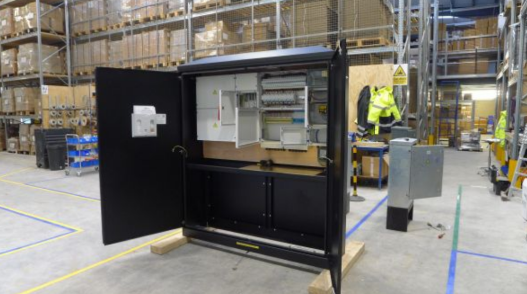
The following information is required by Lucy Zodion to enable the design and specification of feeder pillars to provide LV Electricity Distribution – utilising Fortress type steel pillar enclosures available in galvanised or stainless steel the power distribution pillars can be customised by an in-house Electrical Engineering Team to client and project requirements.
Thorne & Derrick have partnered with Lucy Zodion to provide a free technical support and electrical circuit design service – this includes internal wiring, 3D modelling and pillar schematics using AutoCAD software which is submitted to client for final approval prior to manufacture of the pre-wired electrical distribution pillar.
Effectively a “plug and play” solution to on-site power distribution – alleviating the design stress and cost from the contractor as the pillars are manufactured off-site without requirement to assemble the components and carry out internal wiring to ensure the project programme continues without disruption or delay.
Typically, the following information is required to generate the design of the feeder pillar in either single phase or 3 phase.

Electrical Specification
- DNO/REC Equipment
- DNO/REC Space Required
- Incoming Supply: 1 Phase | 3 Phase
- Cable Size Type Specification: Single | Multicore | Armoured SWA | Unarmoured | Voltage | Conductor Cross Section sqmm
- Incoming Isolation: SW Fuse | SW Disconnect | None | Amp Rating
- Distribution Board Type: Single Phase | 3 Phase | None
- Distribution Board Notes
- Number Of Outgoing Ways:
- Type: SP | TP
- Outgoing Way Protection Devices:
- Number Of BS88 Fuses:
- Number Of RCBO’s:
- Number Of MCB’s:
- Are Outgoing Terminals Required:
- Direct Connect To Distribution Board:
- Outgoing Cable Sizes:
Group Switching
- Time Clock: Normal | Solar | Analogue | Digital
- Contractor Control: Incoming Supply | Outgoing Ways
- Number Of Outgoing Ways Switched:
- Override Switch: Yes | No
Feeder Pillar Extras
- Light
- RCD Socket
- Heater
- Normal Thermostat
- Tamperproof Thermostat
- Commando Sockets
- DC Immune RCD
- Cat Flap
- Feeder Pillar Details
- Minimum Pillar Size: Height | Width | Depth
- Maximum Pillar Size: Height | Width | Depth
- Lucy Fortress Feeder Pillar Part Code (if known)
The safe electrical isolation and termination of low voltage cables all feeder pillars can be supplied with earth bars mounted to the backboard – pictured here is an 8 way earth bar terminating LV green-yellow insulated earth cables 600/1000V.

💡 The Lucy Westminster range of retractable pillars provide “pop-up power” onsite, outside and on demand when temporary electricity is required.

Type Tests Of Feeder Pillars
Prior to factory despatch and in line with electrical testing according to standard BS EN 61439 all mechanical and electrical cable terminations and connections are checked before despatch of the distribution pillars.
Once delivered to site it is recommended the installation guide is observed and if any technical queries arise please do not hesitate to contact us – check all terminal connections prior to energisation or commissioning to ensure no cable compression, damage or loosening of the connections has occurred during transportation or installation.
Should you require any commercial or technical support relating to the design, supply and installation of pre-wired feeder pillars please contact us.


Cut Outs – Lucy Zodion DNO Approved Street Lighting Cut Outs
LV, MV & HV CABLE JOINTING, EARTHING, SUBSTATION & ELECTRICAL EQPT
T&D are Specialist Distributors of products to provide safe and reliable LV HV Electrical Cable & Power Distribution Systems – we are highly customer responsive and absolutely committed to providing a world-class service.
We provide expert technical support and supply from a multi-million pound stock holding:
| Cable Joints, Terminations & Connectors | Earthing & Lightning Protection |
| Cable Accessories, Lugs & Glands | Circuit Protection & Fuses |
| Cable Cleats & Clamps | Electrical Safety Equipment |
| Cable Pulling & Laying Equipment | Arc Flash Clothing & Protection |
| Cable Duct Seals & Transit Systems | Surge Arresters & Bushings |

Read our Blog with Lucy Zodion: Cut-Outs & Isolators – What’s the Difference?
Power Distribution Feeder Pillars For Carpark Lighting Schemes Located In Flood Plane Area
September 12th, 2018
T&D Main UK Suppliers Of Lucy Zodion Feeder Pillars
Feeder Pillars
Case Study 2
Thorne & Derrick, the Specialist Distributor for Lucy Zodion, the UK’s market-leading manufacturer of standard and custom engineered feeder pillars recently supplied a bespoke power distribution pillar for a carpark lighting scheme located in a flood plane area of the UK – the LV power supply required upgraded power distribution system following damage and devastation caused by the floods of 2017.
Lucy Zodion developed customer specific feeder pillars for installation in the retail park with a 2 metre tall pair of pre-wired power distribution enclosures. The pillars with ingress protection of IP66 ensure water entry is minimised during flood conditions.
The 100A three phase DNO power supply of low voltage electricity ensures outdoor areas are sufficiently illuminated to provide safe and secure evening access to the car park zone within the retail park.
For further information about the complete range of pillars please see Lucy Fortress Feeder Pillars.
Power Distribution Feeder Pillars
Features
- Durable – feeder pillars made from heavy duty stainless steel, the pillar shells are durable to withstand extreme weather conditions, while protecting the low voltage electrical equipment within for prolonged use and public safety. As the site is prone to flooding, Lucy Zodion developed taller feeder pillars that elevated components to one meter above ground level.
- Safe – with water ingress a key consideration for the pillar designs, Lucy Zodion provided a electrical power distribution solution that would protect interior components, even when submerged in water (for up to 30minutes). This was made possible by ensuring the feeder pillar IP66 ingress protection. Further IP68 cable glands were installed within the pillar’s pre-wired terminals to ensure external wiring was protected once entering the enclosure.
- Bespoke – Due to the nature of the project and the location of the pillars, standard products were not suitable for the specification. Lucy Zodion helped to ensure pillars were designed to include:
-
- 1 Lucy Zodion Photocell to control the lighting scheme with an additional time-clock should carpark lighting require further programming
- 2 A switch fuse included and distribution section populated with MCB’s to power and control supply from the electricity company to the lighting scheme
- 3 An internal anti-condensation heater within each enclosure to keep inner components dry aiding longevity of both the pillar and the devices within
- 4 An LED service light in each feeder pillar as well as a twin service socket to aid routine maintenance when routine checks and upgrades take place
-
Pictured: Customised feeder pillars completed assembled and build prior to despatch from Lucy Zodion factory.
Fortress Feeder Pillars From Lucy Zodion : Galvanised & Stainless Steel 20+ Sizes
Feeder Pillars
T&D distribute the complete range of Lucy Zodion pillars for low voltage power distribution to the building services, rail, construction, utilities, oil and gas, retail and leisure, ports, airports and heavy industries – GRP feeder pillars, cast iron, galvanised and stainless steel types customised to your application:
- Pre-Wired Power Distribution Panels (Outdoor IP65 & Underground Retractable)
- Substation Power, Cable Distribution & LV Interconnection Panels (Onshore Wind)
- DNO Single & 3 Phase Network Pillars (25A-800A)
- Network Rail & Electrification – Station & Trackside Pillars (incl. London Underground)
- Low Voltage Connections – New Housing & Commercial Development Pillars (LV)
- Defence Estates MoD – Load Shedding Fuse Pillars
- Lighting Feeder Pillars – Street, Road, Flood, Sports Stadium & Car Parks
- BT Telecommunications & Interface Pillars
- Environment Agency – Rivers, Coastal & Waterways
- Cast Iron Electrical Distribution Pillars – National Heritage & Historic Buildings
- Also: Street Lighting Cut Outs
➡ For further information about how Lucy Zodion provide control and power distribution products for street lighting applications, please review the Lucy Titan (Cut-outs) and Lucy Trojan (Isolators) ranges of products.
➡ Contact us to discuss how T&D and Lucy Zodion can provide innovative custom design solutions and ex stock delivery of standard feeder pillars to your project.
Read our Blog with Lucy Zodion: Cut-Outs & Isolators – What’s the Difference?
Landlords Feeder Pillars – An Example Specification
August 28th, 2018
Feeder Pillars
-
uploaded by Chris Dodds - Thorne & Derrick Sales & Marketing Manager
Thorne & Derrick are the leading designer, distributor and supplier in the UK of feeder pillars manufactured by Lucy Zodion – a complete range of standard, customised and pre-wired types from the Lucy Fortress range of feeder pillars are available to suit all LV Electrical Power Distribution requirements.
This includes power distribution pillars to provide LV electricity supply to new housing developments, multi-occupancy buildings and permanent supply kiosks for properties.
Here follows an example of a Landlords Feeder Pillar specification highlighting the flexibility and capability of Thorne & Derrick to liase with consultant engineers and specifiers to meet the needs and electrical power requirements of the residential, housing and accommodation market sectors.
FEEDER PILLARs
21.1 A new landlords service is to be provided as indicated on the drawing. This will consist of a weatherproof secure enclosure housing a distribution board, commonly referred to as a feeder pillar.
21.2 Provide a Thorne & Derrick International landlords feeder pillar. Type Fortress size 16 hot dipped galvanised feeder pillar finished in RAL 6026 complete with Yale lock and door activated internal lighting kit options.
21.3 Provide a concrete base for the feeder pillar in accordance with the manufacturers specifications.
21.4 Provide a MEM Memshield 3 125A 8 way TPN distribution unit to the landlords feeder pillar.
21.5 Provide attendance for electricity meter installation.
21.6 Provide 16sqmm 6491X single core PVC cable tails for DNO ISU in 100mm galvanised trunking.
21.7 Provide local isolator to DNO ISU electrical intake.
21.8 Cable from isolator to DB in 16sqmm 6944X (4 core cable) + 10sqmm CPC 6419X.
21.9 Refer to feeder pillar distribution board schedule for further details.
21.10 Provide 4 number 90mm twinwall cable ducts through concrete base for buried electrical service connections.
22 LANDLORDS SERVICES TO CANOPIES
22.1 The front canopies are to be to be partially stripped and altered.
22.2 Refer to the removal of services section for necessary removals and adaptations necessary to effect the works.
22.3 New ambient down lighting shall be provided to the canopies as detailed on the drawing. Provide new luminaires as detailed on drawing. The existing electrical and lighting circuits have been identified on the as installed information (provided for reference) and utilised for the new lighting. Each unit has an independent circuit. Identify existing feed and extend the circuit to the new luminaires. New cabling to be 1.5sqmm 3182B flexible Low Smoke Zero Halogen (LSZH) cable.
22.4 Provide connections to proposed canopy bus stop signs as detailed on the drawing. These signs shall be wired off the existing canopy lighting circuits. New cabling to be 1.5sqmmmm 3182B.
22.5 Dependant on phasing, alterations to the canopy will expose circuits running through one canopy onto the next. Allow to dress and protect these electrical circuits during the course of the works.
A downloadable specification form is available to initiate the electrical engineering design of all Lucy Zodion type feeder pillars.
Custom Feeder Pillars are readily available in a range of special and format feeder pillars to meet specific applications; they can be made from galvanised steel , or stainless steel and can be painted to suit the customers individual needs.

Galvanised & Stainless Steel | Cast Iron | GRP | Pre-Wired | Electrical Power LV

Largest UK Feeder Pillar Stocks – fast delivery from stock or on short lead-times
➡ Further Reading
THORNE & DERRICK SPECIALIST ELECTRICAL DISTRIBUTOR
LV ♦ MV ♦ HV
T&D distribute the most extensive range of LV, MV & HV Cable Jointing, Terminating, Pulling & Installation Equipment – we service UK and international clients working on underground cables, overhead lines, substations and electrical construction at LV, 11kV, 33kV and EHV transmission and distribution voltages.
- Key Products: MV-HV Cable Joints & Terminations, Cable Cleats, Duct Seals, Cable Transits, Underground Cable Protection, Cable Jointing Tools, Feeder Pillars, Cable Ducting, Earthing & Lightning Protection, Electrical Safety, Cable Glands, Arc Flash Clothing & Fusegear.
- Distributors for: 3M, ABB, Alroc, Band-It, Catu, Cembre, Centriforce, CMP, Elastimold, Ellis Patents, Emtelle, Furse, Lucy Zodion, Nexans Euromold, Pfisterer, Polypipe, Prysmian, Roxtec.

LV – Low Voltage Cable Joints, Glands, Cleats, Lugs & Accessories (1000 Volts)

MV HV – Medium & High Voltage Cable Joints, Terminations & Connectors (11kV 33kV EHV)
Cable Laying – Underground Cable Covers, Ducting, Seals & Cable Pulling Equipment
T&D, CATU Electrical Safety & Arc Flash Protection Specialists for SAP’s, Linesmen, Jointers & Electrical Engineers – Largest UK Stockist
An Installation Guide For Feeder Pillars
August 22nd, 2018Installation Of Retractable Type Feeder Pillars Manufactured by Lucy Zodion
-
uploaded by Chris Dodds - Thorne & Derrick Sales & Marketing Manager
Feeder Pillars
INTRODUCTION
This article covers the installation and maintenance of Pre-wired Feeder Pillars & Retractable Power Pillars as distributed by Thorne & Derrick and manufactured by Lucy Zodion.
This article is to provide assistance to the end user in the installation, maintenance and operation of their feeder pillars – it is not exhaustive and a suitably qualified person should be consulted if in any doubt. It is important to note that any modifications made to the pillars without authorisation by Lucy Zodion are outside the scope of this article.
Retractable Type Feeder Pillars
Lucy Zodion supply two types of retractable power supply feeder pillars namely ‘Castle’ and ‘Westminster’ types – these feeder pillars are part of the Lucy Fortress range of Low Voltage Electrical Distribution Equipment.
These feeder pillars mount flush to the top paving surface when not in use and are pulled up for use when LV power supply is required. Feeder pillars typically supply low voltage power sockets for supplying temporary power to events such as markets, outdoor events and broadcasting. Pillars are available in a variety of specifications, including single and three phase electrical connections and data sockets, as specified by the end user.
A downloadable specification form is available to initiate the electrical engineering design of all Lucy Zodion type feeder pillars.
♦ Electrical Regulations
This Blog written with the support of Lucy Zodion should be read in conjunction with BS 6423:2014 (this replaced BS 6423:1983), the Code of Practice for maintenance of LV electrical switchgear and control gear for electricity voltages up to and including 1000V/1kV.
All electrical work should be conducted in accordance with the Electricity at Work Regulations 1989.
All feeder pillar installations should be designed, tested and installed in accordance with the IET Wiring Regulations BS7671 Requirements for Electrical Installations – any other local regulations in force at the time should be observed.
Installing Feeder Pillars
Pre-wired Electrical Distribution Feeder Pillars
Prewired pillars can be mounted either on the supplied metal root, which is buried in the ground see Figure 1 below, or bolted directly to a concrete base.
Lucy Zodion do not specify the exact nature of installation as it is the customer’s duty to consult a suitably qualified civil engineer for feeder pillar installation.
The following procedure is for guidance only:
- Excavate a trench to the depth of the root section plus the depth of the solid base the unit will mount on, and approximately 30 cm greater than the width and depth of the feeder pillar
- Lay a solid base to the trench, for example paving slabs
- Place feeder pillar on to base and draw cabling into pillar
- Backfill trench with suitable gravel
- We advise capping of the gravel with concrete in the base of the feeder pillar and make good the surrounds with suitable material
➡ It is the customer responsibility to ensure the suitability of the site for the feeder pillar unit specified.

Figure 1 Pre-wired Feeder Pillars – Method of Installation
Retractable power pillars are mounted flush with the existing road/paving surface, and have recesses manufactured at a suitable depth to continue the existing surface material onto the folding
doors of the feeder pillar to leave a safe installation with low visual impact.
Figure 2 below is supplied for guidance only and a suitably qualified civil engineer should always be consulted to determine the exact method of installation.
It is crucial that the unit is equipped with suitable drainage. Lucy Zodion recommend using a 100mm drain pipe with positive drainage to the main sewer. While the low voltage installation is IP67 rated, incorrectly replaced caps and covers allow opportunity for ingress of water and long term exposure can permanently damage to internal components of the feeder pillar.

Figure 2 Westminster Retractable Feeder Pillar – Method of Installation
Westminster Retractable feeder pillars are supplied with recess pockets of a suitable depth for the proposed infill material. This depth is specified at order. Infill material must be installed flush with the surface and around the lock cover and hinges. Some means is necessary to hold the material in place when the feeder pillar is in the vertical, raised position, e.g. solvented grab adhesive.

Figure 3 – Top Cover Of Westminster Retractable Feeder Pillar
Electrical Requirements
Pre-wired feeder pillars and retractable power pillars are supplied pre-wired and tested at Lucy Zodion’s factory. A copy of the test documentation, along with a schematic drawing of the Lucy Zodion supplied equipment, is supplied with the pillar. It is assumed that electrical installation is conducted by a suitably qualified and skilled person and the following information is for general guidance only.
➡ A full test in accordance with BS7671 must be carried out, and a certificate issued, by the installing party after installation on site.
Electrical Connection Of The Feeder Pillar
Feeder pillars are typically supplied with a single phase 230V or 3 phase 415V electrical power supply feed from either a DNO/REC or private supply. Suitable space has been left for installation of DNO/REC cut-out if specified; this can be verified with reference to the drawings supplied with the pillar.
DNO/REC power supplies are connected to the pre-installed equipment using the pre-wired double insulated tails from the main switch disconnect.
Private supply feeder pillars are wired into the equipment using the customer’s cable.
The cable may be wired and connected directly into the main switch disconnect, wired through a cable spreader chamber or wired into a terminal enclosure depending on the size of the incoming cable.
The provision for terminating incoming cable can be determined from the drawings that accompany the feeder pillar or identification of the parts on the pillar.

Lucy Zodion Westminster Feeder Pillars – In Ground Power Distribution Pillars | LV Power Distribution
Lucy Westminster Feeder Pillar Features
- Modified lift assist at first lid to improve longevity and operation ease
- Lift assist added to tower for smoother and safer set-up
- Improved locking system for vibration resistance
- Enhanced Tower latching with slam lock means quick and easy access

Lucy Westminster – Versatile, Discreet , Robust & Safe Power Pillars
Cable Terminations
As feeder pillars are often located remotely from the electrical equipment they supply the outgoing cable sizes often have a large cross-sectional-area for the current rating and cannot be terminated directly into the pillar equipment.
For large outgoing CSA cable sizes suitable cable termination equipment, terminal studs or blocks, are supplied pre-wired into a terminal box.
Incoming and outgoing cables should be wired into these terminals, if supplied, to avoid overcrowding on the main distribution board or where equipment is unable to accept cables of the size specified.
Smaller cable sizes can be wired directly onto the equipment as appropriate.
Suitable space has been left for the cable glanding of outgoing unarmoured or armoured cables, in the form of cable gland plates on the distribution or terminal enclosure, a cable spreader chamber or a horizontal length of galvanised trunking.
Earthing
A dedicated ten way, brass earth block with an adjacent label reading ‘SAFETY ELECTRICAL CONNECTION, DO NOT REMOVE’, is supplied in a prominent and easily assessable location on the feeder pillar backboard. The pillar and all accessible metal parts within the pillar and all CPC earth in pre-wired equipment are equipotentially bonded to the earth block.
It is essential that pillars are connected to a suitable earth upon installation.
Electrical Connection Of The Feeder Pillars
Retractable feeder pillars are supplied with a terminal enclosure mounted in the fixed base of the unit and attached to the outgoing circuits via a pre-installed flexible cable. Once cable terminals have been connected and appropriate tests conducted the supplied Magic Gel should be used.
Magic Gel Instructions:
- Empty both sachets into a suitable mixing container
- Mix thoroughly; pour into the terminal box to above the height of the terminals
- The Magic gel starts to cure in about 4 minutes and will fully cross-link in about 10 minutes depending on temperature
- The Magic gel can be broken up and removed should the installation require alteration
In all cases the installation must be connected to a suitable earth supply. The installer should check the earth loop impedance of the installation as this cannot be verified at the factory. Unsupported lengths of cable should be kept to a minimum.
Where there is more than one cable they shall be connected along their length at not more than 1 metre intervals.
Operation : Pre-wired Pillars
This section covers standard equipment often supplied pre-wired into Lucy Zodion pillars.
For special equipment not covered in this manual please contact Thorne & Derrick.
All pre-wired pillars are supplied with isolation devices which can be locked off.
It is essential that the supply is isolated before any covers are removed from enclosures. For work to be carried out on the incoming terminal board or switch disconnect it is necessary to isolate the supply coming into the feeder pillar.

Figure 4 Common Components of Pre-Wired Pillar
Switch Disconnect
Switch disconnect isolates the main incoming supply from the rest of the equipment in the feeder pillar.
Switch disconnects may be SP & N, TP & N, SP&SN or TP &S N as required by the customer.
In cases where a switched neutral is installed the live phases always cut out first when the switch is disconnected. All main isolators are capable of being locked off to allow safe working on the equipment.
It is essential to lock-off the device when working remotely from the pillar, for example double sided or double length feeder pillars, or equipment being supplied from the pillar.
Switch disconnects may be Fuse Combination Units which are suitable for making, breaking and isolation. The correct fuse for the device is installed prior to the unit leaving the Lucy Zodion factory.
Should the fuse require replacement it is essential that the correct rating of BS88 HRC fuse is fitted. The switch fuse can be locked-off to isolate the rest of the system from the incoming electrical power supply.
24 Hour Board
24 Hour Board provides a continuous, overload protected supply to electrical equipment within installation.
Usually this supply is the main panel board or fuse board of the installation.
In cases where the main board is group switched an auxiliary board will be supplied to supply 24 hour power the pillar equipment (e.g. light, heater and socket) and the group switch control equipment.
Socket outlets
Socket outlets for use by normal persons are supplied as standard via an overload protected, residual current device, e.g. RCBO, RCCD on the 24 Hour board. Periodic testing of this device is required via the test button on the unit.
Group Switch
Group switch controls a group of equipment, typically street lighting installations, via a control system, such as a photocell or timer. Be sure to isolate a group switch from the incomer on the 24 Hour board, as group switches are remotely controlled they can go live at any time.
Group switch control – the group switch can be controlled by a timer, photocell or an override. A typical installation with a group switch would control street lighting.
- Solar Time Clock – is pre-set in the factory for the final geographical location of the pillar. To override the time switch press and hold the two central buttons on the controller until the output condition of the unit changes in the display.
- Photocell – either one or two part, switches the group switch contactors when ambient light levels fall below pre-determined level. One part photocells have the sensor mounted on the side of the pillar as standard. Two part photocells allow the installer to install the sensor head remotely from the pillar, the terminal from the photocell are wired into the unit in the pre-mounted 125x125mm enclosure within the pillar.
- Override Switch – switches the contactors on for testing of outgoing circuits, or for functional switching of the load. The use of a timer in conjunction with a photocell allows the lighting to be illuminated when either light levels or time dictates
Residual Current Devices
Residual current devices all socket outlets are protected by a residual current device as well as suitable overload protection. It is the end users’ responsibility to ensure that all equipment connected to sockets within the feeder pillar is within the specified load and connected by a suitable cable as required by BS7671. All residual current devices should be tested periodically and at least every six months.
Surge Protection
Surge protection devices are installed, if specified, to suit the earth system indicated by the customer e.g. TT or TNS. Should the earth system change from the original specification it will be necessary to change the surge protection device. The surge protection device has an end of life indicator based on the amount of KVA diverted to earth. This requires periodic inspection. Should the device indicate an end of life condition the unit will need to be replaced by a competent person.
Operation Instructions
Raising and lowering: – the unit is unlocked using the supplied T key. The key is inserted and twisted through 90 degrees. The key is held in the lock and is used as a handle to pull the top cover open. The socket unit is raised using the handle on the top and locked into position using the two retractable lugs. The cover is subsequently lowered back into position.
The socket box is fitted with a tilt switch which switches on the supply to the unit as it is raised. The LED on the top of the box indicates that the power is connected. Plugs are connected into the sockets by rotating the cover anti-clockwise until it is released and able to swing up. The sockets are functionally switched using the toggle switch on the RCD.
➡ To maintain the IP rating of the unit all caps must be properly replaced on the sockets and the RCD cover fully tightened before the unit is lowered after use. Lowering is the reversal of opening.
Electrical Supply
Functional switching for sockets is provided by the isolation switch on the RCD. The transparent plastic cover provides ingress protection to the residual current devices. To access the switches rotate the knurled thumbwheels anti-clockwise until the bolt exit the hole and pull down the flap. Sockets are activated by pushing the switch into the up position.
Test the functioning of the residual current device at the time of switching. This is achieved by pressing the test button, upon which the power should instantly be cut and switch revert to the down position. It is essential that the transparent cover is closed while the pillar is in use in order to avoid possible contact between water and electrical parts.
Retractable power pillars are fitted with cenorm style outdoor sockets with a minimum ingress protection of IP67.
Generally sockets will be 16A or 32A Single phase or 3 Phase. Single phase sockets are identified by a blue body and three phase by a red body, current ratings are printed on
the labels on the socket cover. Sockets and plugs of different types are not interconnectable and only plugs that match the current and phase rating of the socket should be plugged into it.
To open socket covers, rotate the grey outer wheel quarter turn and hinge the cover upwards. Holding the cover up, plug the plug into the socket, with the tang pointing downwards. The cover should locate with the raised lug on the socket to ensure security of installation. Removing the plug is a reverse of the process and it is essential to ensure all covers are properly replaced before lowering the power pillar.

Figure 5 Westminster Socket Box
Inspection & maintenance
➡ Warning: Feeder pillars may contain accessible live parts even when the unit has been isolated. Equipment covers should only be removed by skilled and authorised personnel.
The following recommendations are for guidance only as the nature of the environment and the conditions of operation will have a significant influence on the maintenance schedule required.
General Maintenance Policy
This document describes the routine maintenance requirements of Lucy Zodion Pre-wired pillars and retractable power pillars. It is assumed throughout that necessary precautions to render the apparatus safe to work on have been undertaken by suitably qualified personnel.
Conditions of use will have a significant impact on the service intervals of the equipment and it is advised that when units are installed in adverse conditions such as coastal areas, areas of high pollution, very frequent switching of loads or areas accessible to the public, that the maintenance interval is reduced to ensure reliable and safe operation of the equipment.
Under normal conditions of service, Lucy Zodion Prewired Pillars and Retractable Power Pillars are intended to give years of trouble free service. The best way to ensure trouble free service of your product is to conduct regular visual inspections and report any defects to a suitably qualified person for maintenance. As the retractable pillar is located below ground level, it is recommended that the adjacent area is kept clean around the lock mechanism.
Safety Precautions
Only skilled and instructed persons may remove covers from enclosures within the pillars. In order to avoid live working, installations should be isolated from the supply prior to maintenance within enclosures. General good housekeeping techniques, including the regular removal of any foreign bodies that have fallen into the tub are recommended as part of the maintenance programme.
* Incorrect alignment with a suitable drainage point, or blockage to existing drainage pipework on retractable power pillars may cause the container to fill with water, therefore route cause for blockage should be remedied by technically competent persons.
Socket caps fitted as standard are designed for compliance to IP67 rating, when correctly aligned and fitted. Please note that the socket caps incorporate a recess on the reverse face and in the folded flat position condensation may form in this recess which is released when unscrewing the cap, for socket connection, this has no detrimental effect on safety or performance.
Feeder Pillars – Lucy Zodion Fortress
Service Schedule For Lucy Zodion Fortress Feeder Pillars
Should you require competitive pricing, delivery or any further technical support to enable to specification or purchase of feeder pillars please do not hesitate to contact us.
| Maintenance Period For Feeder Pillar | Operations | Who Should Perform |
| After each use | Ensure all caps are replaced properly on IP rated sockets. |
End -User |
| Close and lock units appropriately |
End -User | |
| At least every 6 months | Test Residual Current Devices |
End -User |
| Ensure locking mechanism is cleaned |
End -User | |
| Removal of any foreign bodies. |
End -User | |
| At least Annually | Visual inspection : Damage – internally and externally, Paintwork, Operation of internal light. |
End -User |
| Test operation of pillar heater and light |
End -User | |
| Lubrication of Pillar hinges band locks |
End -User | |
| Five Years | Exterior and accessible interior parts cleaned |
End -User |
| Enclosures opened for examination and lubrication |
Qualified and skilled personnel only |
|
| Surge protection end-oflife indicator, inspection. |
Qualified and skilled personnel only |
|
| Fifteen years | General Overhaul | Qualified and skilled personnel only |
THORNE & DERRICK SPECIALIST ELECTRICAL DISTRIBUTOR
LV ♦ MV ♦ HV
T&D distribute the most extensive range of LV, MV & HV Cable Jointing, Terminating, Pulling & Installation Equipment – we service UK and international clients working on underground cables, overhead lines, substations and electrical construction at LV, 11kV, 33kV and EHV transmission and distribution voltages.
- Key Products: MV-HV Cable Joints & Terminations, Cable Cleats, Duct Seals, Cable Transits, Underground Cable Protection, Cable Jointing Tools, Feeder Pillars, Cable Ducting, Earthing & Lightning Protection, Electrical Safety, Cable Glands, Arc Flash Clothing & Fusegear.
- Distributors for: 3M, ABB, Alroc, Band-It, Catu, Cembre, Centriforce, CMP, Elastimold, Ellis Patents, Emtelle, Furse, Lucy Zodion, Nexans Euromold, Pfisterer, Polypipe, Prysmian, Roxtec.
LV – Low Voltage Cable Joints, Glands, Cleats, Lugs & Accessories (1000 Volts)
MV HV – Medium & High Voltage Cable Joints, Terminations & Connectors (11kV 33kV EHV)
Cable Laying – Underground Cable Covers, Ducting, Seals & Cable Pulling Equipment
T&D, CATU Electrical Safety & Arc Flash Protection Specialists for SAP’s, Linesmen, Jointers & Electrical Engineers – Largest UK Stockist
Road Lighting Feeder Pillars
June 7th, 2017T&D Main UK Suppliers Of Lucy Zodion Feeder Pillars
Feeder Pillars
Case Study 1
Working with the M&E Contractor and their Consultant Engineers, T&D have supplied road lighting feeder pillars to provide reliable low voltage power distribution to an urban design and infrastructure project predicted to deliver £74.2m in gross value added to the local economy in South Yorkshire.
For further information about the complete range of pillars please see Lucy Fortress Feeder Pillars.
- Application: Feeder Pillar To Provide Road Lighting
- Type: Single Door Galvanised Steel Feeder Pillar
- Pillar Size: Height 1294mm x Width 1100mm x Depth 400mm
- Order Code: Lucy Zodion Fortress 12-HDP-3
- Notes: Road Lighting Feeder Pillars With Lucy SS12 Miniature Photo Cell Unit (LUX)
- See Complete Range Of Feeder Pillars
Lucy Zodion Fortress 12-HDP-3 Feeder Pillar Specification
- Height Above Ground 1294mm
- Root Section 350mm
- Width 1100mm
- Depth 400mm
- Door Opening Height 1007mm
- Door Opening Width 1000mm
- Working Depth 375mm
- Pillar Backboard Size 1080x1075mm
Fortress Feeder Pillars From Lucy Zodion : Galvanised & Stainless Steel 20+ Sizes
Feeder Pillars Features & Benefits
The road lighting feeder pillars were supplied by T&D with anti-vandal lock, detachable root section and painted to RAL9005 Abcite Black colour scheme.
Abcite thermoplastic powder coatings provide tough, impact resistant protection for outdoor pillars without a primer undercoat – excellent corrosion and UV protection.
Project Details: Advanced Manufacturing and Research Centre Campus (AMRC2), Sheffield UK – 860,000 sq ft of advanced manufacturing and research space, 468,000 sq ft for a residential training centre and conferencing and 16,000 sq ft for outdoor and indoor recreation. The original University-backed AMRC on the Advanced Manufacturing Park (AMP) now comprises more than 40 companies including Rolls-Royce and Boeing – a nucleus of innovation, research and technology designed for collaboration and rapid commercialisation.
How we secured #greenbelt release for AMRC2 at the former #Sheffield city airport: https://t.co/UGF0ggVjFn pic.twitter.com/I6lYWQfFRx
— DLP Planning (@DLPPlanning) July 11, 2016

The feeder pillars will distribute power to the exterior lighting columns

Lucy Zodion Westminster Feeder Pillars – retractable in-ground “pop-up” power pillars
Feeder Pillars
T&D distribute the complete range of Lucy Zodion feeder pillars for low voltage power distribution to the building services, rail, construction, utilities, oil and gas, retail and leisure, ports, airports and heavy industries – GRP, cast iron, galvanised and stainless steel types customised to your application:
- Pre-Wired Power Distribution Panels (Outdoor IP65 & Underground Retractable)
- Substation Power, Cable Distribution & LV Interconnection Panels (Onshore Wind)
- DNO Single & 3 Phase Network Pillars (25A-800A)
- Network Rail & Electrification – Station & Trackside Pillars (incl. London Underground)
- Low Voltage Connections – New Housing & Commercial Development Pillars (LV)
- Defence Estates MoD – Load Shedding Fuse Pillars
- Lighting Feeder Pillars – Street, Road, Flood, Sports Stadium & Car Parks
- BT Telecommunications & Interface Pillars
- Environment Agency – Rivers, Coastal & Waterways
- Cast Iron Electrical Distribution Pillars – National Heritage & Historic Buildings
- Also: Street Lighting Cut Outs
➡ For further information about how Lucy Zodion provide control and power distribution products for street lighting applications, please review the Lucy Titan (Cut-outs) and Lucy Trojan (Isolators) ranges of products.
➡ Contact us to discuss how T&D and Lucy Zodion can provide innovative custom design solutions and ex stock delivery of standard feeder pillars to your project.
Read our Blog with Lucy Zodion: Cut-Outs & Isolators – What’s the Difference?
