Cable Lugs & Crimping Using The Hexagonal Crimp Method
uploaded by Chris Dodds - Thorne & Derrick Sales & Marketing Manager
Hexagonal Crimping Of Cables
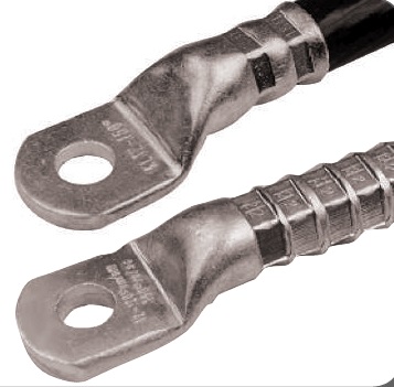
Thorne & Derrick International, based in the UK, are leading suppliers of cable crimp lugs and associated crimping tools for Low, Medium & High Voltage Cables and Power Systems– this series of articles by Klauke discusses the theory and practise of installing compression type cable lugs and connectors.
Klauke cable lugs and crimping tools are used by Jointers, Linesmen, Panel Builders and Electrical Engineers to install underground cables and overhead line conductors on power, transmission and distribution networks including LV MV & HV systems, 11kV-33kV.
Hexagonal crimping is suitable for both copper and aluminium conductors
A professional hexagonal crimp generally requires use of crimping dies which match sizes of conductors and connecting material
The classification of manufacturer specific crimping dies and cable lugs is rather regulated by the cross section of the cable
The primary application of standardised hexagonal crimps is with electric utilities within a range from 10kV up to 30kV
Depending on the tool narrow or wide cable crimps can be used
Hexagonal crimps for aluminium and copper
In daily practice hexagonal crimping is the most common kind of crimping of cable lugs and cable connectors for medium/high voltage power cables and systems.
The reason is very simple – this type of crimp is suitable for both copper and aluminium conductors. Hexagonal crimps can be found in panel building industries as a manufacturer specific crimp and also as a DIN standard lug crimp for example in utilities (aluminium and copper conductors including 11kV and 33kV power cables).
Technically the hexagonal crimp is characterised by a centrical and constant force effect applied during the crimping operation from all sides and creating a larger contact area.
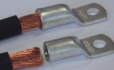
Hexagonal crimps are suitable for both copper (above) and for aluminium (below)
The individual strands of the conductors are being deformed homogeneously in their entirety without any damage. The results are good electrical properties of these connections.
Mechanical and electrical properties of tubular and DIN compression cable lugs are being defined by the IEC 1238 part 1. It defines the requirements that an electrical connection has to fulfil for a permanent safe operation within intended applications.
The cross section of a hexagonal crimp performed with a manufacturer recommended tool shows the uniform positioning of conductors in the cable lug
Apart from mechanical pull out tests also electrical durability tests are included. The field of application of hexagonal crimps comprises the processing of conductors as per:
VDE 0295 Classification
Class 1: round solid conductors
Class 2: round stranded conductors
Class 5: round fine stranded conductors
Class 6: round finest stranded conductors
Conductor types acc. to DIN VDE 57295: round solid, round stranded, fine stranded, compacted
In addition hexagonal crimps per DIN 46235 and DIN 44267 can also be used for processing of non-tension and full tension connections of aluminium cables per DIN 48201 Part 1 of aluminium ropes per DIN EN 50182.
The correct Crimping tool
For processing cable lugs per DIN 46235 crimping dies with die codes per DIN 48083 can be used. This combination enables hexagonal crimps per DIN 46235 and 46267. For hexagonal crimps of standard tubular cable lugs it is suggested to strictly observe manufacturers tool recommendations.
Hexagonal crimps are exposed to high loads. For this reason only high quality tools should be used which in addition feature special functions guaranteeing correct and safe crimps. Battery powered crimping tools of the latest generation give an acoustic warning if the required crimping force has not been reached.
High quality mechanical crimping tools can only be opened when the crimping operation has been completed. Until then an integrated locking device blocks the tool – a totally completed cable crimp is important as the required compression of the crimp material is only reached at the end of the crimp phase.
Preparation For a professional crimp
A professional hexagonal crimp generally requires use of crimping dies which match sizes of conductors and connecting material. That means that cable lugs and connectors need to correspond to the dimensions of the conductor and crimping die.
Incorrect Crimping
Incorrect Crimping
Correct Crimping
Incorrect and correct crimps in comparison: An incorrect crimp (crimping,middle: low force crimping, and usage of incorrect crimping tools can result in an increase in joint resistance and may jeopardise the installation)
An incorrect combination can lead to low compression – excess compression crimps with potentially fatal consequences: Faulty cable crimps and lugs can lead to increased contact resistance with rise of temperatures which in the worst case can cause fire.
Incorrect or materials processed with in-appropriate tools can cause heavy defects on installations resp. electrical equipment
Cable lugs of poor quality and/or processing may cause fire
For this reason manufacturers of branded electrical and cable accessory products such as Klauke recommend for crimping operations their cable lugs and connectors solely use of their own appropriate crimping tools. High quality crimping dies can be recognised by a polished surface with rounded edges.
Example of a crimping die with polished profile
These crimping dies are precisely manufactured and guarantee a constant and neat deformation of copper or aluminium. Prior to the cable crimping operation the electrical engineer or cable joint must ensure that the conductors need to be brushed to achieve a metallic clean surface and that oxide layers have to be removed from the aluminium cables.
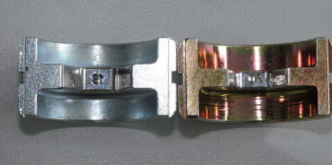
While stripping cable conductors it has to be observed that some are not being damaged and that bared length is more or less identical with insertion length of cable lug or connector. Crimping dies need to be clean and metallic bright. To avoid the incorrect die selection Klauke differentiates in colour, silver stands for aluminium dies and yellow gold for copper die sets.
Left: crimping die for aluminium, silver coloured; right: crimping die for copper (yellow-gold colour)
Tip: Klauke recommends to start crimping operations on cable lugs always from the palm towards the cable. In this case the compressed material can slide towards the cable end which hasn’t been crimped.
A cable lug or connector always needs to be crimped under consideration of the crimping direction and use of appropriate tools
Manufacturer specific hexagonal crimps
For hexagonal crimping operations we distinguish between two versions:
The hexagonal crimp as per DIN 48043 Part 4
The manufacturer specific hexagonal crimp
Within the standard copper range the so called manufacturer specific hexagonal crimps are used for cable types as per VDE 0295 class 2.
Permissible – manufacturer specific hexagonal crimp
Manufacturers with a reputation for quality such as Klauke offer hexagonal crimping dies for processing standard copper tubular cable lugs as per EN 13600 and approved cable conductor connections as per IEC 1238.
These cable lugs are being used for instance in the construction of electrical control cabinets because of design and smaller dimensions. To accomplish a professional crimp it is of great importance to use high quality tools. Only using such tools guarantee that a sufficient degree of compression is being achieved to insure optimum contact properties.
To achieve an IEC approved connection it is necessary that all components used match each other – this includes cable lug, crimping tool and suitable die set.
This concerns the cable lug and appropriate conductor but also the suitable appropriate crimping die and crimping tool – resulting in a safety engineered system.
The classification of manufacturer specific crimping dies and cable lugs is – other than with DIN standard crimps – not controlled by die codes; it is rather regulated by the cross section of the cable specified in sqmm.
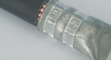
Manufacturer specific crimp with indication of cross section
Every manufacturer is responsible for the electrical durability of connections being processed with their products – specified tests have to be provided as evidence.
As a professional and safe hexagonal crimping is dependent from an exact matching of crimping dies and cable lugs Klauke recommends for crimping their cable lugs solely use of their own tools as well. In case of special applications it is advisable to involve the preferably identical manufacturer of both tools and cable lugs.
Brand manufacturers will perform – if required – for the specific application pull out tests (accelerated tests) as per IEC and where applicable also tests of the electrical contact resistance and recommend depending on the results adequate tools and materials.
Hexagonal crimps for aluminium & copper
In particular when it comes to international projects and processing of specific cable types for instance in China or India IEC or customer specific standards can be complied with in terms of safety.
Standardised hexagonal crimping
The primary application of standardized hexagonal crimps is with electric utilities within a range from 10 kV up to 30 kV. The reason is the very homogeneous crimping which produces a consistent electrical field and consequently has a positive impact as to an unwanted field scattering.
Other than with indent crimps hexagonal crimps do not show any mechanical indent of material which in case of electrical field control needs to be balanced with a conductive compound.
Mainly for electric utilities: DIN standardised hexagonal crimp
Copper cable lugs as per DIN 46235 and copper connectors as per DIN 46267 part 1 can be crimped with crimping dies as per DIN 48083 T4.
For aluminium cable lugs as per DIN 46329 and compression connectors as per DIN 46267 part 2 and other aluminium connectors and cable lugs with appropriate tube dimensions as well hexagonal crimping dies as per DIN 48083 part 4 can be used.
Hexagonal profiles as per DIN comply with the dimensional specifications of DIN cable lugs and are standardized within given tolerances.
However, there are no specs given as to the crimp width which is either 5mm for copper or 7mm for aluminium. Identification marks on DIN cable lugs give important notes as to manufacturer, dimensions and design of cable lugs, which indicates the crimping tool resp. crimping die as necessity for crimping operations conforming to standards.
This inscription is found behind the manufacturer code.
For instance KL18 stands for
KL: manufacturers code (in this case Klauke)
18: tool resp. die code
For a professional completion of a standardised crimp the tool code is decisive: The tool code of crimping die used has to conform with the tool code of the cable lug.
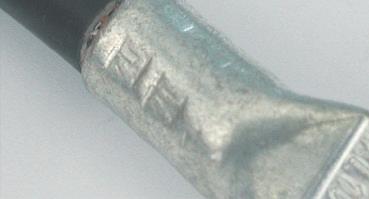
The imprinted tool code “18” on the cable lug (above) gives information on the crimping die to be used. The completed crimp (below) with imprint “18” on the cable lug proves that the correct crimping die was used
The die code is engraved mirror-inverted on the crimp surface of the crimping die and once crimping operation has been completed it is visible on the cable lug.
Tool codes correspond approx. with the tube dimensions of the cable lugs. For copper die codes range from 5 up to 58; this corresponds to cross sections from 6sqmm up to 1000sqm. In the same way hexagonal crimping dies for aluminium and appropriate tube dimensions of these cable lugs and connectors are standardised.
Tool code on the cable lug and imprinted code verify a correct crimp
Wide or narrow crimps
Depending on the tool narrow or wide crimps can be used. On a cable lug of 50sqmm cross section for instance one has the alter-native to do two narrow crimps or one wide crimp.
Narrow crimp (above) and wide crimp (below)
Tools with a crimping force of up to 6t (60kN) are suitable solely for narrow hexagonal crimps of 5mm width on copper. Tools with a crimping force of more than 12t (120kN) are suitable for wide crimps according to manufacturers instruction.
Usually the electrician prefers narrow crimps as tools are lower in weight and easier to handle. For cable assembly, however, wide crimps are preferred as they reduce the number of crimps required and consequently save time.
For standard tubular cable lugs mostly narrow crimps are being used. Mechanical and battery powered tools – lower in weight – and up to 60kN are being applied.
A special feature is with aluminium cable lugs: To compensate the lower conductivity of aluminium compared with copper the narrow crimp in this case is 7mm.
Also important: The DIN standard does not prescribe a specific crimp width either for copper or for aluminium.
This information is given by the manufacturer by means of wide and narrow markings on DIN compression cable lugs. It should be observed that cable lugs resp. connectors and tools including crimping dies come from one single source, e.g. a brand manufacturer.
Crimp marking indicate to narrow resp. wide crimping
Indent crimps
Old, but proved and tested: indent crimping constitutes the oldest type of crimping operations in electrical installations. In panel and control cabinet construction even today it is a widely used method of crimping copper – as classical indent crimp and “W” indent crimp.
Further Reading
Review other Blogs in this series of articles about Cable Lugs, Crimping Cables & Tools:
Thorne & Derrick are Specialist Distributors of leading manufacturers of Cable Accessories, Jointing & Installation Equipment.
LV MV HV cable accessories used to joint, terminate, connect, cleat and gland power cables to air and gas insulated substations, transformers, switchgear and overhead line networks.
Hover over our Interactive Electricity Grid to learn more about our product ranges.
LV 600/1000V ◊ MV 11kV 33kV ◊ HV 66kV 132kV
Substation & Overhead Line Electrical Safety Equipment
Manufactured by CATU Electrical to enable the safe construction, maintenance and repair of underground cables and overhead lines network up to EHV (400kV).
uploaded by Chris Dodds - Thorne & Derrick Sales & Marketing Manager
Thorne & Derrick International, based in the UK, are leading suppliers of cable crimp lugs and associated crimping tools for Low, Medium & High Voltage Cables and Power Systems– this series of articles by Klauke discusses the theory and practise of installing compression type cable lugs and connectors.
Klauke cable lugs and crimping tools are used by Jointers, Linesmen, Panel Builders and Electrical Engineers to install underground cables and overhead line conductors on power, transmission and distribution networks including LV MV & HV systems, 11kV-33kV.
Crimping cables according to Class 5 & Class 6 DIN 57295 using Klauke “F” cable lugs
Tube diameter is matched to the conductor size to guarantee a professional cable crimp
Cable lugs for switch cabinets with special narrow palm cable lugs
Crimping copper cables and conductors using stainless steel and nickel cable lugs
A well known problem for every electrician or cable jointer is trying to insert a stranded or fine stranded conductor into the cable lug or cable splice and some wires cannot be inserted. To avoid this problem renowned manufacturers offer specialist application connectors and cable lugs for the jointing and termination of LV MV HV cables.
Cable Lugs, Strandings & Conductors
With these specialist application cable lugs all types of cables can be used – the design and construction of the cable lug to be selected is determined by the cable stranding and conductor type. The cable conductor characteristics of cable types are as classified in the DIN Standard 57295.
Class 1 is a solid/round conductor providing both the smallest diameter and largest cross-sectional area (CSA in sqmm) – this is the simplest conductor but mechanically weak with solid conductors prone to breakage after several bending cycles. The cable conductors are categorised into Classes based on the total number of strands per conductor – the higher the Class, the more strands in the conductor:
Class 1 Round single / solid conductors
Class 2 Round multi-stranded conductors – typically 7 or 19 strands
Class 5 Fine stranded conductors (Multi-stranded general flexible use)
Class 6 Fine stranded conductors (Extra multi-stranded dynamic use)
DIN 57295: DIN VDE 0295:1980-09; VDE 0295:1980-09
Conductors of Cables & Flexible Cords For Power Installation (VDE Specification)
Conductor types acc. to DIN VDE 57295: round solid, round stranded, fine stranded, compacted
Cable Lugs For Fine & Very Fine Stranded Conductors
The above mentioned problem of spliced cables per Class 5 and Class 6 according to DIN 57295 is being avoided when using Klauke “F” type series cable lugs. These lugs are designed for processing larger cross section conductors in voltage applications up to the short circuit tested rating of the cable lug.
Compared with standard tubular cable lugs the “F type” lugs have a larger tube diameter – the cable lugs have a flared entry which eases cable location into the barrel of the lug.
Unprofessional and individually matched cable lugs can create serious safety defects in electrical installations.
The advantages are obvious – “F type” cable lugs ensure an easy and safe insertion of the conductor, the unravelling of the cable strands is avoided and the complete conductor fits into the cable lug prior to compression using appropriate crimping tools and die sets.
Cable lugs “F type” for fine stranded conductors for easy insertion with no splicing
This is also a safety-related issue – a reduction of the cross section area of the cable conductor caused by not inserting all the strands is being avoided and the complete cross section of the cable is maintained. Markings on the F-type cable lug barrel provide information of the product, e.g. manufacturer, dimension and design.
Marking “KL 12 150 F” indicates:
KL: Manufacturer Klauke
12: Metric bolt size for connecting bolt: size M12
150: Cross section of conductor in sqmm
F: Tubular cable lug design and construction
For professional crimping of F-type cable lugs the indent or quad point crimping method is recommended with the appropriate crimping tools and the correct indent profile.
F-type cable lug shows professional indent crimp
To avoid over or under compression the correct tooling is a pre-requisite. An incorrect crimping connection can result in increased joint resistance leading to an increase in temperatures and in the worst case in fire.
Klauke recommends use of their own crimping tools to achieve and guarantee professional crimps according to VDE standards. In addition to “F-type” cable lugs some manufacturers offer appropriate butt-connectors for splicing, extension and repair of cable conductors.
They also feature a flared entry and larger tube dimensions. A central restriction insures uniform insertion of the cable ends, and insure the crimping recommendations for F-type lugs are adhered to.
“F-type” cable lugs and butt connectors conform to the normative requirements of the EN 13600 standard and are manufactured from electrolytic copper for excellent conductivity.
A cross sectional view of an indent crimp (with manufacturers recommended tool) shows the even arrangement of conductor in the lug
For corrosion protection the cable lugs are available tin plated from cross sections ranging between 10sqmm up to 300sqmm. In addition to the normal design “F-type” cable lugs are also available as 45° resp. 90° angled versions as well as inspection holes to check whether the conductor is fully inserted prior to crimping-up the lug using the cable tool.
As with all other connections these products are subject to test standard IEC 1238 Part 1, which guarantees a safe electrical and mechanical connection has been achieved. Cable lugs manufactured by Klauke are subject to a special annealing process to help relieve material stresses and hardness.
This reduces the chance of material fracture and is an additional safety feature. The quality of cable lugs can often be recognised by visual characteristics. A burr free lug, a flat palm and a cleanly machined end are indicative of a high quality product.
Note: IEC 61238-1:1993 Is Now Withdrawn. Compression & Mechanical Connectors For Power Cables With Ccpper Or Aluminium Conductors – Part 1. Contact T&D.
Cable Lugs For Solid Conductors
For processing and crimping solid conductors (Class 1 DIN VDE 57295) the use of tubular cable lugs “E” type is recommended which are also manufactured from electrolytic tin plated copper. Their tube diameter is matched to the conductor size to guarantee a professional cable crimp.
Professional crimp on a solid conductor with matched tube dimension
Application is in all areas where solid conductors are being mostly used, e.g. manufacture of switchgear, transformers and engines.
A hexagonal indent crimping is being recommended – again it has to be observed that both cable lugs and crimping tools come from the same manufacturer.
Cable lugs for solid conductors can be recognized by their smaller tube diameter and the marking “E”. For example: KL 10 50 E.
Cross sections usually range from 6sqmm up to 50sqmm. The range is being completed by butt-, T- and cross connectors having the appropriate internal tube diameters.
Cable Lugs For Switch Cabinets
In many cases working area in switch cabinets is very tight and connecting conductors to high-power switchgears can be a problem In case of larger cross sections standard cable lugs do not fit into the compact connecting terminal.
Special cable lugs for switch cabinets (type SG) for safe connection also of conductors
For such applications many manufacturers have designed special narrow palm cable lugs (Klauke SG cable lugs) which fit comfortably.
Direct comparison of standard cable lugs (left) and cable lugs with narrow palm for switch cabinets
The narrow palm lug is also thicker than standard cable lugs ensuring the same amount of electrolytic copper has been used.
Despite a narrower palm no performance is lost. Thus these cable lugs therefore comply with a professional connection for stranded conductors according to DIN- VDE Class 2 as typically used in switch cabinets.
A hexagonal or indent crimp is recommended – conductor cross sections range from 35sqmm up to 300sqmm. The hole dimensions comply with industry sizes of connecting terminals, e.g. 6, 8, 10, 12 and 16mm.
Professional crimp on stainless steel cable lug for application in ambient temperatures of up to 400°C
Versions with inspection holes are also available – it is dangerous and incorrect to file the palm of a normal cable lug to the size of the connecting terminal. Such manipulation can result in increased temperatures and fire in the worst case.
Shows the thicker palm of SG cable lugs for switch cabinets, using the same amount of copper as used in a standard cable lug.
Stainless steel cable lugs
for aggressive environments
Especially for adverse environments and for crimping copper conductors stainless steel and nickel tubular cable lugs have been designed. Stainless steel cable lugs are particularly acid and corrosion resistant and are typically used in chemical industries in areas exposed to sea water i.e. the earthing of masts on sailing yachts.
An additional benefit of these cable lugs is the temperature resistance. Consequently these lugs can be used in ambient temperatures up to 400°C.
At higher temperatures of up to 650°C – common in the construction of furnaces – nickel cable lugs represent the best solution. Both stainless steel and nickel cable lugs can be used for all common cable types.
A correctly crimped stainless steel cable lug used for applications where the environment can reach 400º C
Cross section ranges from 0.5sqmm up to 95sqmm. Generally an indent crimp is recommended. The same applies for stainless steel and nickel butt connectors with barrier.
Further Reading
Review other Blogs in this series of articles about Cable Lugs, Crimping Cables & Tools:
Thorne & Derrick are Specialist Distributors of leading manufacturers of Cable Accessories, Jointing & Installation Equipment.
LV MV HV cable accessories used to joint, terminate, connect, cleat and gland power cables to air and gas insulated substations, transformers, switchgear and overhead line networks.
Hover over our Interactive Electricity Grid to learn more about our product ranges.
LV 600/1000V ◊ MV 11kV 33kV ◊ HV 66kV 132kV
Substation & Overhead Line Electrical Safety Equipment
Manufactured by CATU Electrical to enable the safe construction, maintenance and repair of underground cables and overhead lines network up to EHV (400kV).
Thorne & Derrick together with Lucy Zodion can offer a range of SLF street lighting cut-outs (SLCOs) which are now approved for use by every Distribution Network Operator (DNO) in the UK.
The high level of specification status of their cut-outs for street lighting applications on both the UKPN and WPD networks is a clear demonstration of Lucy Group’s commitment to keeping LV electrical connections safe and reliable.
The Lucy Zodion SLF range of street lighting cut outs use high quality materials and provide a wide range of features that help ensure robust and reliable protection and isolation across a number of street lighting network types and applications.
Additionally, the Lucy Zodion brand of Fortress type feeder pillars are extensively specified and installed throughout the UK DNO LV Electricity Distribution network.
➡ For further information about how Lucy Zodion provide control and power distribution products for street lighting applications, please review the Lucy Titan (Cut-outs) and Lucy Trojan (Isolators) ranges of products.
Cut Outs
Here is the current street lighting cut out approval listing according to UK DNO designation:
DNO Approved Products
DNO Area
DNO
Lucy Zodion Code
Cut Out Description
WPD*
THM0048847
SLF IPC Type 1 HEX Drive Clear Cover
(SNE)
THM0041767
SLF IPC Type 2 HEX Drive Clear Cover
(CNE)
ENW
0260009009
SLF 25A SLCO Type 1 (SNE)
0260010009
SLF 25A SLCO Type 2 (CNE)
NPG
THM0001978
SLF 25A SLCO TYPE 2(CNE) POLYCARBONATE
THM0001979
SL DNO DP 25A SLCO (CNE) POLYCARBONATE
THM0001970
SLF 25A Single Pole SNE
SPEN
0260009009
SLF 25A SLCO Type 1 (SNE)
0260010009
SLF 25A SLCO Type 2 (CNE)
SSE
0260009009
SLF 25A SLCO TYPE 1 (SNE)
0260010009
SLF 25A SLCO TYPE 2 (CNE)
0260026007
SL DNO DP 25A SLCO (CNE)
UKPN*
0260011007
SLF 25A SLCO TYPE 1 (SNE)3mm HEXDRIVE
0260012009
SLF 25A SLCO TYPE 2 (CNE)3mm HEXDRIVE
*sole supplier status
Street Lighting | House Service | DNO | Heavy Duty – complete range of Cut Outs
T&D distribute the most extensive range of LV, MV & HV Cable Jointing, Terminating, Cable Pulling & Installation Equipment – we service UK and international clients working on underground cables, overhead lines, substations and electrical construction at LV, 11kV, 33kV and EHV transmission and distribution voltages.
uploaded by Chris Dodds - Thorne & Derrick Sales & Marketing Manager
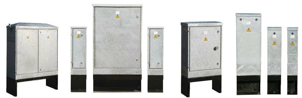
Thorne & Derrick are the leading designer, distributor and supplier in the UK of feeder pillars manufactured by Lucy Zodion – a complete range of standard, customised and pre-wired types from the Lucy Fortress range of feeder pillars are available to suit all LV Electrical Power Distribution requirements.
This includes power distribution pillars to provide LV electricity supply to new housing developments, multi-occupancy buildings and permanent supply kiosks for properties.
Here follows an example of a Landlords Feeder Pillar specification highlighting the flexibility and capability of Thorne & Derrick to liase with consultant engineers and specifiers to meet the needs and electrical power requirements of the residential, housing and accommodation market sectors.
FEEDER PILLARs
21.1 A new landlords service is to be provided as indicated on the drawing. This will consist of a weatherproof secure enclosure housing a distribution board, commonly referred to as a feeder pillar. 21.2 Provide a Thorne & Derrick International landlords feeder pillar. Type Fortress size 16 hot dipped galvanised feeder pillar finished in RAL 6026 complete with Yale lock and door activated internal lighting kit options. 21.3 Provide a concrete base for the feeder pillar in accordance with the manufacturers specifications. 21.4 Provide a MEM Memshield 3 125A 8 way TPN distribution unit to the landlords feeder pillar. 21.5 Provide attendance for electricity meter installation. 21.6 Provide 16sqmm 6491X single core PVC cable tails for DNO ISU in 100mm galvanised trunking. 21.7 Provide local isolator to DNO ISU electrical intake. 21.8 Cable from isolator to DB in 16sqmm 6944X (4 core cable) + 10sqmm CPC 6419X. 21.9 Refer to feeder pillar distribution board schedule for further details. 21.10 Provide 4 number 90mm twinwall cable ducts through concrete base for buried electrical service connections.
22 LANDLORDS SERVICES TO CANOPIES
22.1 The front canopies are to be to be partially stripped and altered. 22.2 Refer to the removal of services section for necessary removals and adaptations necessary to effect the works. 22.3 New ambient down lighting shall be provided to the canopies as detailed on the drawing. Provide new luminaires as detailed on drawing. The existing electrical and lighting circuits have been identified on the as installed information (provided for reference) and utilised for the new lighting. Each unit has an independent circuit. Identify existing feed and extend the circuit to the new luminaires. New cabling to be 1.5sqmm 3182B flexible Low Smoke Zero Halogen (LSZH) cable. 22.4 Provide connections to proposed canopy bus stop signs as detailed on the drawing. These signs shall be wired off the existing canopy lighting circuits. New cabling to be 1.5sqmmmm 3182B. 22.5 Dependant on phasing, alterations to the canopy will expose circuits running through one canopy onto the next. Allow to dress and protect these electrical circuits during the course of the works.
A downloadable specification form is available to initiate the electrical engineering design of all Lucy Zodion type feeder pillars.
Custom Feeder Pillars are readily available in a range of special and format feeder pillars to meet specific applications; they can be made from galvanised steel , or stainless steel and can be painted to suit the customers individual needs.
Galvanised & Stainless Steel | Cast Iron | GRP | Pre-Wired | Electrical Power LV
Largest UK Feeder Pillar Stocks – fast delivery from stock or on short lead-times
T&D distribute the most extensive range of LV, MV & HV Cable Jointing, Terminating, Pulling & Installation Equipment – we service UK and international clients working on underground cables, overhead lines, substations and electrical construction at LV, 11kV, 33kV and EHV transmission and distribution voltages.
A Guest Article by Carl Pike – Director Filoform UK
The following contributed post provides an overview of the dangers of inadequately protected building penetrations and the need for duct sealing solutions with independently tested fire-proofing specification to protect people and property against the devastating effects of fire.
What is Fire Stopping?
Fire stopping has been brought more to the fore over the last few years than ever before.
The best way to explain the need of a fire-stop is to treat a multi-room dwelling or factory or any structure as a series of boxes or compartments. These boxes need to join physically by their walls or floors, even doors or windows. All these items are regulated and proven fire withstand products and procedures are in place to ensure any building is built or modified in accordance with the underlying need to stop fire spreading.
The fire tightness of one of these boxes is only as strong as the weakest entry point.
Did you know, fire can double in volume per minute it is lit. It doesn’t take long at this alarming rate to fill a room with fire. Fire does not respect any boundaries put in its place, but a certified system like ‘FiloSeal+HD FIRE‘ installed in the correct manner will stop or prevent the premature spread of fire to the next compartment through cable ducts, entries or penetrations.
Fire stopping got its foothold first in the marine industry. Probably because a loss of integrity of one compartment will mean a total loss of the vessel. It was in fact a development from the second World War German super sub captured by the Swedish that led to fire stopping products of a modular nature being developed by a company still going today. In the super sub, the system was used to prevent the rattle of pipes and wires within the sub, hence improving the sound signature of a hidden submarine.
Research we have done leads us to the improving of fire stopping on land as a direct result of several disasters in the USA starting with the 1906 San Francisco earthquake. This was followed by the New York garment district factory fire of 1911 and perhaps most scarily by the Browns Ferry Nuclear plant fire of 1975. This last event was caused by an open candle flame being used to detect air path leaks in foam based cable and pipe transit areas!
Not surprisingly, the nuclear industry was the first on land industry to take fire stopping seriously.
The use of the correct fire stopping product in the correct way and in the correct place ensures fire tightness of a compartment or room. There are plenty of products which work on floor/wall or ceiling wall interfaces. Many of these are flexible to allow for building expansion and contraction. Some other ways of sealing do not allow for this expansion; cements and mortars for instance. These materials do have their place but not always.
The last area we have not yet mentioned is the service penetrations into a room or compartment. These are the necessary services such as water, electricity and data cables which without them a room is almost useless.
Penetrations may come in via a wall, floor or ceiling. All must be adequately and correctly fire stopped. These services will need a flexible and re-enterable method of being sealed. The flexibility due to temperature expansion of both cables and pipes; the re-enterability due to the almost constant development of a buildings use and services.
Rockwool and insulation’s of the type are fire-retardant but are not in themselves a fire stopping method. They are perfectly suited to holding a system in place during installation but should never be relied upon to be the actual stop itself.
Fire stopping expanding foams
Please don’t get us started with this.
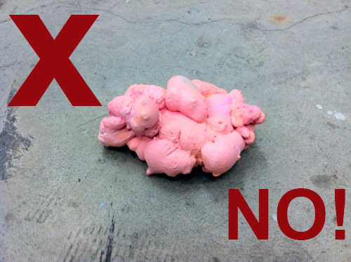
The use of so-called ‘fire rated’ foams for fire stopping of service penetrations or control joints is sadly becoming more prevalent everywhere. This trend could lead to serious consequences if a fire happens in a building where they’re used,
What do we mean by ‘fire rated foams’?
The fire rated foams we’re talking about are those that are delivered by way of an aerosol can or canister, which foam up when they’re dispensed – much like canned shaving foam.
They’re typically polyurethane based, and our understanding is they might all be coming from the same factory overseas, imported under many different product brands. To add to the problem, many are now dyed red or pink like above to signify their suitability for fire stopping applications. DON’T USE THEM!
Modular sealing systems work admirably out at sea where rigorous compliance is ensured on a day to day basis. On land, a more flexible system would work better; one where less is known up front about the exact cables or pipes to be found in any service penetration. One that can cope with irregular sized holes and mis-shaped ducts.
The correct system to use in service penetrations ON LAND
Their are many fire rated sealing systems available that claim their product is suitable for penetrations with cables present but you must really be careful and select the correct product for the situation you are sealing. Important note; a fire rating applies to an ‘as fire tested’ system, or an otherwise approved configuration. Only when a particular (and I must add proprietary) brand of product is installed in an identical way to the approved configuration does the entire system or configuration achieve the fire rating as described.
Filoform has heavily invested time and money into developing a fire rated duct sealing solution that offers the user and and end customer the following;
Flexible & Simple – a one box solution that has everything is one kit to seal a cable duct regardless of the size or number of cables running through the duct – we’ve kept selecting and installing our product ‘simple’ little upfront planning needed.
NON Hazardous – FiloSeal+HD FIRE contains no hazardous chemicals which makes COSHH and getting our product approved with any Health & Safety departments an easier process.
Many Resistances – Not only is our product fire resistant, tested to BS EN1366-3:2009, it also offers, 2 bar pressure resistance against water and gas / rat, rodent and termite protection (Mastotermes Darwiniensis) Northern Australian termites) and resists many harsh chemicals and gases, for example, Hydrogen Sulfide, Methane, Chlorine, Hydrocarbons and many more.
Expandable – We’ve developed FiloSeal+HD FIRE to easily be installed in circular ducts and also irregular shaped penetrations. FiloSeal+HD FIRE can be supplied with a retrofittable cable transit frame which is used if a structure or space will not allow fitting of a seal into the structure itself.
Affordable – Even with the heavy investment and time we spent designing and developing FiloSeal+HD FIRE, we’ve made this cable duct seal affordable but still offering extremely high quality components with proven test reports and a solid history of sealing solutions.
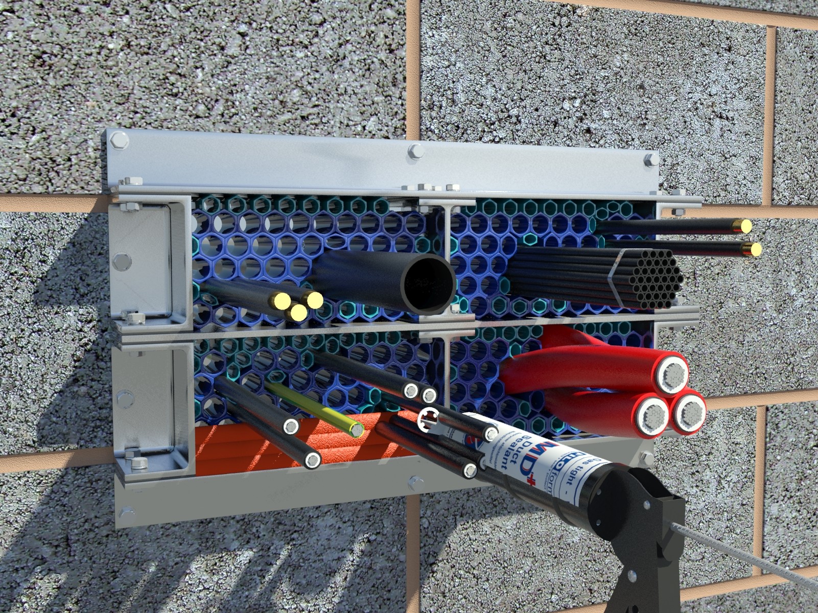
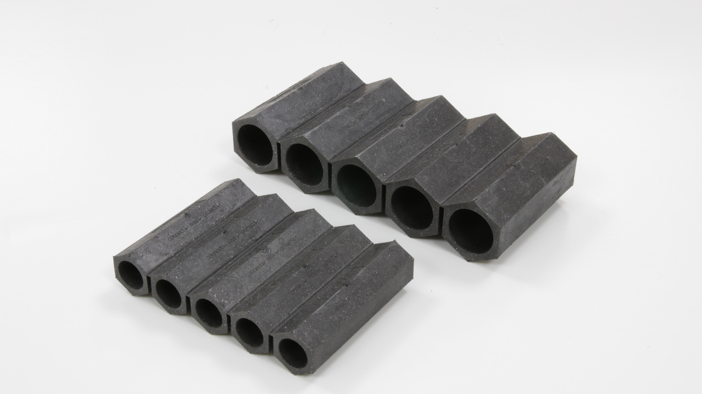
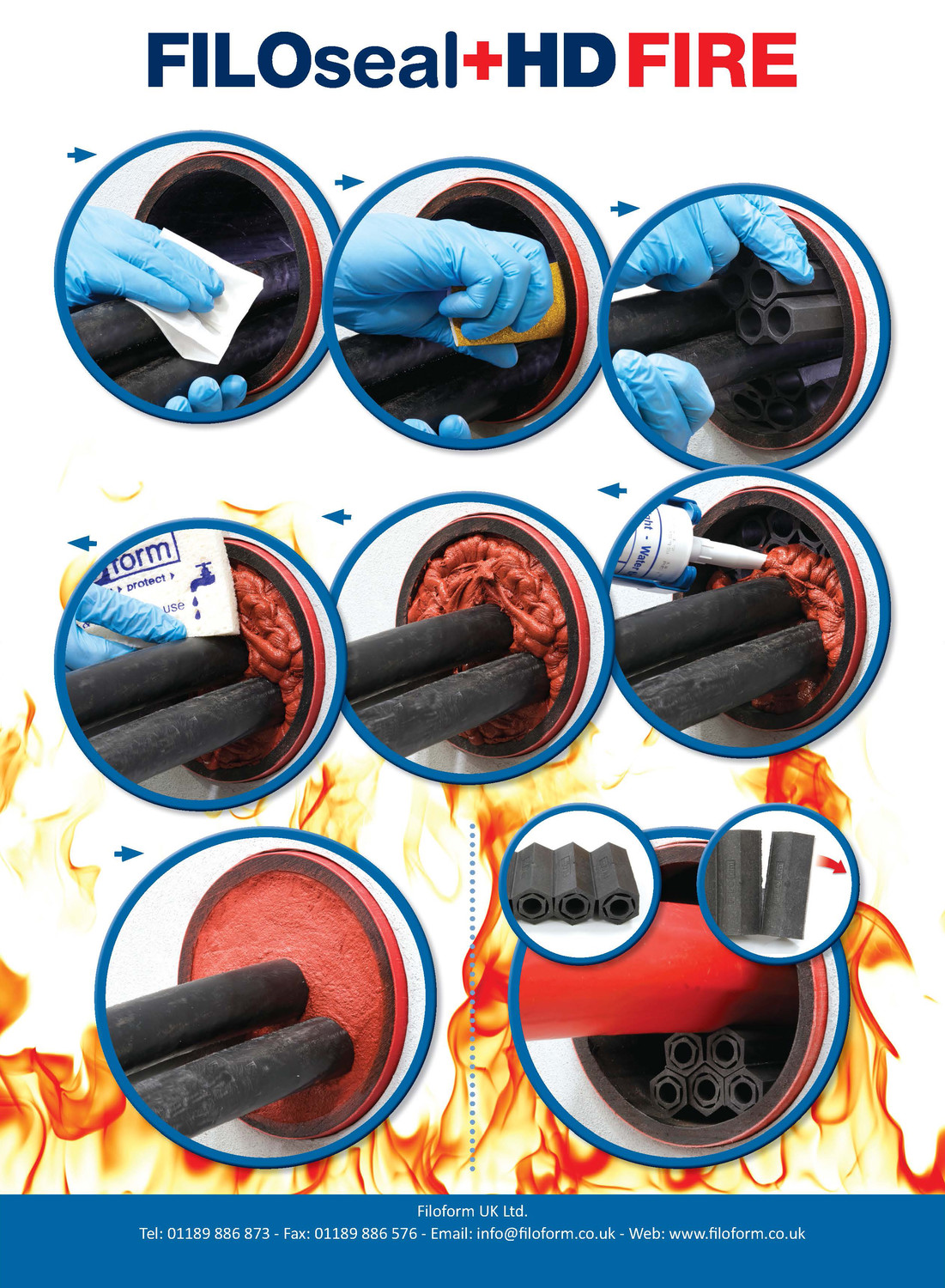
FiloSeal+HD FIRE provides a strong support system using the fire resistant hexagonal blocks made of our specially formulated material called ‘Formite’ which builds up like a honeycomb structure.
FiloSeal+HD FIRE is suitable for sealing empty or any cable configuration or pipes contained in one duct and also allows easy re-entry of the seal to add or remove cables or pipes as required.
Filoform FiloSeal+HD FIRE
FiloSeal+HD FIRE is very easy to apply regardless of the type of cable scenario in the cable ducts as it uses strong, but flexible hexagonal blocks to support the cable and provide a strong backing for the seal.
The unique design of the hexagonal blocks makes positioning and separation of the cables very simple while also providing a strong backing for the MD+ to be applied on.
Up to 4 hours fire resistance in transit frames (single side)
T&D distribute the most extensive range of LV, MV & HV Cable Jointing, Terminating, Pulling & Installation Equipment – we service UK and international clients working on underground cables, overhead lines, substations and electrical construction at LV, 11kV, 33kV and EHV transmission and distribution voltages.
Celebrating Charlie & Ella’s Level 4 Sales Executive Apprenticeships At Thorne & Derrick International, we are proud to champion talent development and recognise the dedication required to achieve professional growth. We are therefore delighted to congratulate Charlie Baines and...
Thorne & Derrick will be Exhibiting at Solar & Storage Live UK 2026 at the NEC Birmingham from 22nd–24th September, showcasing our support for HV Cable Accessories, Joints, Terminations, Separable Connectors, Cable Tooling and Grid Connection Products used across...