

Blog
Cable Trough Explained | Cable Protection
July 23rd, 2026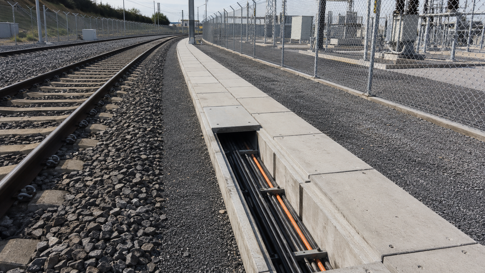
Cable trough is a protective cable containment system used to route, support and protect power, signalling, telecoms, control and communications cables above ground or at shallow depth. Cable troughing is commonly used across railways, substations, highways, utilities, industrial sites, renewable energy projects and electrical infrastructure.
In simple terms, a cable trough provides a defined channel for cables. The trough helps protect cables from mechanical damage, weather exposure, accidental impact, vegetation, debris and unauthorised interference, while still allowing access for inspection, repair, cable jointing and future cable additions.
Cable troughs are available in different materials and formats, including concrete cable troughs, GRC cable troughs, lightweight composite troughs, straight sections, lids, T-pieces, bends, transitions, channels and elevated troughing systems.
Thorne & Derrick supply cable troughing for power, rail and infrastructure cable protection, including concrete cable trough, GRC cable trough, cable trough lids, bends, transitions and accessories for LV, MV and HV cable routes.
Quick Answer: What Is Cable Trough?
Cable trough is a cable protection and containment system used to route cables safely through rail, power, highway and infrastructure environments. It normally consists of a channel or trough section with a removable lid, allowing cables to be protected while still remaining accessible for inspection, maintenance and future installation work.
Cable troughing is commonly used for LV, MV and HV power cables, signalling cables, telecoms cables, control cables and communications cables. It is especially common in trackside rail environments, substations, power networks and utility cable routes.
What Is Cable Trough?
A cable trough is a physical containment route used to house and protect cables. Unlike a buried duct where the cable is pulled through an enclosed pipe, a cable trough is usually an open channel with a lid fitted over the top.
This makes cable troughing useful where cables need both protection and future access. The lid can be removed so engineers can inspect cables, install additional circuits, carry out jointing work or repair damaged sections without excavating a fully buried route.
Cable troughing systems can be used for:
- Power cables
- Rail signalling cables
- Telecommunications cables
- Control and instrumentation cables
- Fibre optic cables
- Substation auxiliary cables
- Trackside and infrastructure cable routes
The correct trough system depends on cable type, cable quantity, route layout, loading requirement, access needs, ground conditions and project approval requirements.
Where Is Cable Trough Used?
Cable troughing is used where cables need mechanical protection and accessible containment.
Typical locations include:
- Railway trackside routes – protecting power, signalling and telecoms cables along rail infrastructure.
- Substations – routing LV, MV and HV power, control and auxiliary cables.
- Highways – protecting cables for lighting, traffic systems, signage and communications.
- Utilities – housing power and communications cables across infrastructure networks.
- Renewable energy sites – protecting cable routes for solar, wind and battery storage projects.
- Industrial sites – protecting cables in outdoor process, plant and utility areas.
- Bridges, tunnels and embankments – where elevated or lightweight cable troughing may be required.
Cable trough is especially useful where a cable route must remain accessible after installation.
Types Of Cable Trough
Cable troughs are available in different materials and shapes to suit different route conditions.
Cable trough systems may also include straight sections, bends, T-pieces, transitions, joint boxes, brackets, stakes and direction-change accessories.
Concrete Cable Trough
Concrete cable trough is one of the most established cable protection methods used in rail and infrastructure projects. It provides strong, durable, permanent cable containment with removable lids for future access.
Concrete troughs are used to protect power, signalling, telecoms and communication cables from physical damage and environmental conditions. They are particularly common on rail infrastructure, where trackside cable routes need long service life and reliable protection.
Benefits of concrete cable troughing include:
- High mechanical strength
- Long-term cable protection
- Removable lids for access
- Suitable for rail and infrastructure projects
- Protection from environmental and mechanical damage
- Support for future cable jointing, repairs and additions
Power & Cables supplies concrete cable troughs for LV, 11kV, 25kV and 33kV trackside cable protection, including Anderton concrete troughing and Anderlite lightweight concrete trough systems.
GRC Cable Trough
GRC cable trough is manufactured from glassfibre reinforced concrete. It is used where a lighter weight troughing system is needed while still providing cable support and protection.
GRC troughing is commonly used at trackside ground level, over bridges and through tunnels. It can be useful in locations where manual handling, access, elevated installation or route flexibility are important.
GRC cable trough systems may include:
- Channels and lids
- Radiused bends
- T-pieces
- Joint boxes
- Height changes
- Direction changes
- Stakes and brackets
View GRC cable troughing for rail, power and infrastructure routes.
Cable Trough vs Cable Duct
Cable troughs and cable ducts are both used to protect cables, but they are different systems.
For underground ducted cable routes, see cable ducting for LV, MV and HV power cables.
Rail & Trackside Cable Troughing
Railway infrastructure is one of the most common applications for cable troughing. Trackside cable routes must protect power, signalling and telecoms cables while allowing access for maintenance and network changes.
Rail cable troughing is used for:
- Signalling cables
- Telecommunications cables
- Trackside power cables
- Control cables
- LV and MV cable routes
- Tunnel, bridge and elevated route sections
In rail environments, cable trough may need to meet project-specific approvals, load requirements, route design and installation standards. Troughing may also need bends, transitions, tee sections and lightweight alternatives for difficult access locations.
Cable Trough For Power Cables
Cable trough is also used for power cable protection in substations, industrial sites, utilities and renewable energy projects. It can provide a protected route for LV, MV and HV cables while allowing future access for inspection and maintenance.
Power cable troughing can be used where:
- Cables require mechanical protection
- Cable routes must remain accessible
- Future cable additions are likely
- Jointing or repair access may be required
- Above-ground or shallow-depth cable protection is preferred
- Cable ducts are not the most practical route method
For associated installation equipment, see cable pulling and cable laying equipment.
How To Select Cable Trough
Selecting the correct cable trough depends on the route, cables and operating environment.
The correct trough should be selected as part of the complete cable route design, not as an isolated product choice.
Common Cable Trough Mistakes
Cable trough issues are often caused by poor route planning or incorrect product selection.
Common mistakes include:
- Choosing the wrong trough size – insufficient internal space can make cable installation, access and future additions difficult.
- Ignoring lid loading requirements – lids must suit the expected pedestrian, occasional or heavier loading conditions.
- Forgetting route changes – bends, tees and transitions should be planned before installation.
- Using trough where ducting would be better – fully buried routes may be better suited to cable ducts.
- Using duct where access is needed – troughing may be better where cables need frequent inspection or future additions.
- Poor bedding or support – trough sections should be properly supported to prevent instability and damage.
- Overlooking manual handling – concrete trough can be heavy, so lightweight or GRC options may be preferred in some locations.
- Not allowing for cable bend radius – route changes must suit the cables being installed.
- Ignoring project approvals – rail and utility projects may require approved trough systems.
The best cable trough design protects cables while allowing safe access throughout the service life of the installation.
Related Cable Protection Products
Cable troughing is part of a wider cable protection and installation system.
- Cable Trough – troughing systems for rail, power, highway and infrastructure cable protection.
- Concrete Cable Trough – concrete troughs and lids for trackside and infrastructure cable routes.
- GRC Cable Trough – glassfibre reinforced concrete troughing for rail, bridges, tunnels and elevated locations.
- Concrete Utility Cable Troughs – guide to utility troughs and lids for power and communications services.
- Cable Duct – ducting for underground cable protection and cable pulling routes.
- Cable Pulling & Laying Equipment – installation equipment for cable route works.
- Cable Protection Tiles – protective tiles for underground cable routes.
Cable Trough FAQs
Q: What is cable trough?
A: Cable trough is a protective cable containment system used to route and protect power, signalling, telecoms, control and communications cables. It usually consists of a channel with a removable lid.
Q: What is cable trough used for?
A: Cable trough is used to protect and contain cables in rail, power, highway, utility, substation, industrial and infrastructure environments while allowing access for inspection and maintenance.
Q: What is concrete cable trough?
A: Concrete cable trough is a robust cable containment system used for permanent cable protection, especially in rail and infrastructure applications. It normally includes concrete trough sections and removable lids.
Q: What is GRC cable trough?
A: GRC cable trough is glassfibre reinforced concrete troughing. It is used where a lighter weight cable trough system is required, including rail, bridges, tunnels and elevated route sections.
Q: What is the difference between cable trough and cable duct?
A: Cable trough is usually an accessible channel system with removable lids. Cable duct is an enclosed pipe or duct route through which cables are pulled, often underground. Troughing is better where future access is important.
Q: Where is rail cable trough used?
A: Rail cable trough is used along trackside routes, bridges, tunnels and rail infrastructure to protect power, signalling, telecoms and control cables while keeping them accessible for maintenance.
Q: Can cable trough be used for power cables?
A: Yes. Cable trough can be used for LV, MV and HV power cables where the route needs protection and access. It is also used for signalling, telecoms, fibre optic and control cables.
Q: How do you choose the right cable trough?
A: To choose the right cable trough, check the application, cable type, internal capacity, loading requirement, route layout, material, access requirements and project approvals.
Conclusion
Cable trough is an important cable protection and containment system used across rail, power, highway, utility and infrastructure environments. It provides a protected cable route while allowing access for inspection, maintenance, repair, jointing and future cable additions.
Concrete cable trough, GRC cable trough and lightweight troughing systems each have different benefits depending on the route, loading requirement, access needs and project specification.
Thorne & Derrick supply cable troughing, concrete cable troughs, GRC cable troughs, cable trough lids, cable ducts and cable protection products for LV, MV and HV power, signalling, telecoms and infrastructure cable routes.
Cable Glands Explained | Types & Selection
July 23rd, 2026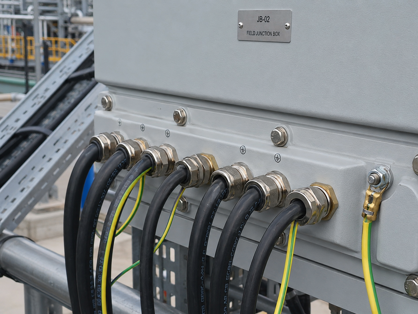
Cable glands are mechanical cable entry devices used to secure, seal and protect cables where they enter electrical equipment, enclosures, junction boxes, control panels, motors, switchgear, lighting, instrumentation and hazardous area equipment.
In simple terms, a cable gland provides a controlled entry point for the cable. Depending on the cable type and application, the gland may provide cable retention, environmental sealing, armour clamping, earth continuity, strain relief, ingress protection and explosion protection certification.
Cable glands are used across LV, MV and HV electrical installations, including industrial plants, utilities, substations, process facilities, offshore platforms, petrochemical sites, rail infrastructure, renewable energy projects, commercial buildings and hazardous area installations.
Thorne & Derrick supply cable glands for industrial, hazardous area and high voltage applications, including CMP cable glands, Prysmian glands, ATEX cable glands, armoured cable glands, unarmoured cable glands, brass glands, stainless steel glands and cable gland kits.
Quick Answer: What Are Cable Glands?
Cable glands are fittings used to terminate and secure cables where they enter electrical equipment or enclosures. They help seal the cable entry, retain the cable mechanically and protect the installation from dust, moisture, impact, vibration and environmental conditions.
For armoured cables, the cable gland may also clamp the armour and provide earth continuity. For hazardous area equipment, certified cable glands may be required to maintain the explosion protection concept of the enclosure or equipment.
What Are Cable Glands?
A cable gland is a component fitted to the entry point of an electrical enclosure or item of equipment. It allows a cable to enter the enclosure while maintaining the required mechanical and environmental protection.
Without a suitable cable gland, a cable entry can become a weak point in the installation. Water, dust, gas, chemicals or contaminants may enter the enclosure, and the cable may not be properly retained against pulling, vibration or movement.
Cable glands are commonly used on:
- Junction boxes
- Control panels
- Motors and pumps
- Switchgear
- Lighting equipment
- Instrumentation equipment
- Hazardous area enclosures
- Industrial power distribution equipment
The correct gland depends on the cable construction, equipment entry, installation environment, required IP rating, material, certification and whether the cable is armoured or unarmoured.
What Do Cable Glands Do?
Cable glands can perform several functions at the same time.
Not every cable gland provides every function. A simple unarmoured gland may provide sealing and retention, while an armoured hazardous area barrier gland may provide sealing, retention, armour clamping, earth continuity and Ex certification.
Types Of Cable Glands
Cable glands are available in many types because cable construction and installation environments vary widely.
Common cable gland types include:
- Unarmoured cable glands – for cables without armour, braid or metallic mechanical protection.
- Armoured cable glands – for SWA, AWA, braided, strip armoured or tape armoured cables.
- Industrial cable glands – for general industrial power, control and instrumentation applications.
- Hazardous area cable glands – certified glands for explosive atmospheres and ATEX/IECEx equipment.
- Barrier cable glands – glands that use a sealing compound or barrier seal where required by the protection concept or installation standard.
- High temperature cable glands – for installations exposed to elevated temperatures.
- EMC cable glands – designed to support electromagnetic compatibility and screen continuity.
- Corrosion-resistant cable glands – often stainless steel or nickel-plated brass for harsh environments.
View cable glands for industrial, hazardous area and MV/HV applications.
Armoured vs Unarmoured Cable Glands
One of the most important selection decisions is whether the cable is armoured or unarmoured.
For example, a gland for a multicore SWA cable may not be the correct option for a single-core AWA cable, braided cable or lead sheath cable. The armour type, bedding diameter, outer sheath diameter and environmental sealing requirement should all be checked.
For CMP SWA gland options, see CMP CW cable glands for steel and aluminium wire-armoured cables.
CMP Cable Glands
CMP cable glands are widely used across industrial, hazardous area, onshore, offshore, power, control, instrumentation and MV/HV cable installations. They are a major cable gland manufacturer and a key part of the Power & Cables gland range.
CMP gland ranges include products for:
- Armoured cables
- Unarmoured cables
- Braided cables
- Lead sheath cables
- SWA and AWA power cables
- Industrial installations
- Hazardous areas
- Medium and high voltage systems
Common CMP cable gland families include CW glands, BW glands, A2 glands, E1W, E2W, CXT, SOLO, ZEN, Triton and barrier gland ranges. The correct range depends on the cable construction, equipment certification, sealing method and installation environment.
View CMP cable glands from Thorne & Derrick.
ATEX & Hazardous Area Cable Glands
Hazardous area cable glands are used where cables enter equipment installed in potentially explosive atmospheres. These environments may be found in oil and gas, petrochemical, chemical, pharmaceutical, offshore, tank storage, fuel handling, grain processing and other hazardous-area industries.
In hazardous areas, the cable gland must be compatible with the equipment protection concept, cable type and hazardous area classification. A standard industrial cable gland is not automatically suitable.
Hazardous area cable gland considerations include the following:
- ATEX and IECEx certification
- Zone 1 or Zone 2 requirements
- Ex d, Ex e, Ex nR or Ex ta protection concepts
- Armoured or unarmoured cable construction
- Barrier or non-barrier sealing requirements
- Ingress protection and environmental sealing
- Material suitability for corrosion or offshore conditions
For hazardous area applications, see ATEX cable glands for Zone 1 and Zone 2 hazardous areas.
Cable Gland Materials
Cable gland material should be selected according to the environment, mechanical requirement, corrosion risk, cable type and equipment material.
For corrosive onshore or offshore locations, protective finishes or 316 stainless steel glands may be required depending on the environment.
Locknuts, Earth Tags, Shrouds & Accessories
Cable glands are often installed with accessories. These accessories help secure the gland, provide earth bonding, protect the gland body or adapt the gland to the enclosure entry.
Common cable gland accessories include:
- Locknuts – used to secure the gland to an enclosure when a threaded entry is not available.
- Earth tags – used to provide an earth bonding connection at the gland entry.
- Shrouds – used to provide additional environmental protection over the gland body.
- Sealing washers – used to help maintain ingress protection at the enclosure entry.
- Reducers – used where the gland thread is smaller than the equipment entry.
- Adaptors – used where thread conversion or entry size adjustment is required.
- Stopping plugs – used to close unused entries in an enclosure.
Cable gland kits are commonly ordered with a locknut, earth tag and shroud where these accessories are required for the installation.
How To Select Cable Glands
Selecting the correct cable gland requires accurate cable and site information. A gland should not be selected from thread size alone.
For CMP ranges, see CMP industrial cable glands.
Common Cable Gland Mistakes
Cable gland selection mistakes can affect safety, sealing, certification and long-term reliability.
Common mistakes include:
- Selecting by thread size only – the gland must match the cable construction and cable dimensions.
- Using an unarmoured gland on an armoured cable – armoured cables require suitable armour clamping and continuity where required.
- Ignoring bedding diameter – the gland must fit the cable beneath the armour as well as the overall cable diameter.
- Using standard glands in hazardous areas – hazardous area equipment may require certified ATEX or IECEx glands.
- Choosing the wrong material – corrosive or offshore locations may need stainless steel or suitable protective finishes.
- Forgetting earth tags and bonding – earth continuity must be considered where the cable armour forms part of the earthing system.
- Poor shroud selection – shrouds must fit the gland and environmental conditions.
- Overlooking enclosure certification – the gland must not compromise the equipment’s IP rating or Ex certification.
- Incorrect installation torque or assembly – glands must be assembled in line with manufacturer instructions.
The correct gland should always be selected using cable data, equipment data and the installation environment.
Related Cable Gland Products
Cable glands are part of a wider cable termination and installation system.
- Cable Glands – industrial, hazardous area, ATEX and MV/HV cable glands.
- CMP Cable Glands – CMP glands for armoured, unarmoured, hazardous area and high voltage applications.
- CMP Industrial Cable Glands – BW, CW, A2, CXT, SOLO, E1W, E2W and other industrial gland ranges.
- ATEX Cable Glands – hazardous area cable glands for Zone 1 and Zone 2 applications.
- CMP CW Cable Glands – CW glands for steel and aluminium wire armoured cables.
- CMP Triton Cable Glands – hazardous area cable glands for armoured and braided cables.
- Hazardous Area Electrical Equipment – glands, cleats, joints and electrical equipment for explosive atmospheres.
- Cable Tools – cutting, stripping, crimping and installation tools for cable termination work.
Cable Glands FAQs
Q: What is a cable gland?
A: A cable gland is a fitting used to secure, seal and terminate a cable where it enters electrical equipment or an enclosure. It helps provide cable retention, environmental protection and strain relief.
Q: What do cable glands do?
A: Cable glands can provide sealing, mechanical retention, strain relief, ingress protection, armour clamping, earth continuity and certification integrity depending on the gland type and installation.
Q: What is an armoured cable gland?
A: An armoured cable gland is designed for cables with metallic armour, such as SWA, AWA, braid, strip or tape armour. It clamps the armour and may provide earth continuity between the cable armour and equipment.
Q: What are CMP glands?
A: CMP glands are cable glands manufactured by CMP Products. They are used for industrial, hazardous area, high voltage, armoured, unarmoured, braided and specialist cable termination applications.
Q: What is an ATEX cable gland?
A: An ATEX cable gland is a certified gland used with equipment installed in potentially explosive atmospheres. It must be suitable for the hazardous area zone, equipment protection concept and cable type.
Q: What is included in a cable gland kit?
A: A cable gland kit often includes the cable gland plus accessories such as a locknut, earth tag and shroud. The exact kit contents depend on the manufacturer and ordering reference.
Q: How do you choose the correct cable gland size?
A: Cable gland size should be selected using the cable bedding diameter, armour range, overall cable diameter, cable construction and equipment thread size. It should not be selected by thread size alone.
Q: Do cable glands need earth tags?
A: Earth tags may be required where an earth bonding connection is needed at the gland entry, particularly where the cable armour forms part of the earthing arrangement. The requirement depends on the installation design and equipment.
Conclusion
Cable glands are essential cable entry components used to secure, seal and terminate cables into electrical equipment and enclosures. They support cable retention, environmental protection, strain relief, armour clamping, earth continuity and hazardous area certification where required.
Correct cable gland selection depends on the cable type, armour construction, bedding diameter, overall cable diameter, thread size, installation environment, material, IP rating, certification and accessory requirements.
Thorne & Derrick supply industrial cable glands, CMP cable glands, armoured cable glands, ATEX cable glands and hazardous area cable glands for LV, MV and HV power, control, instrumentation and electrical equipment installations.
Surface Tracking Explained | MV HV Terminations
July 23rd, 2026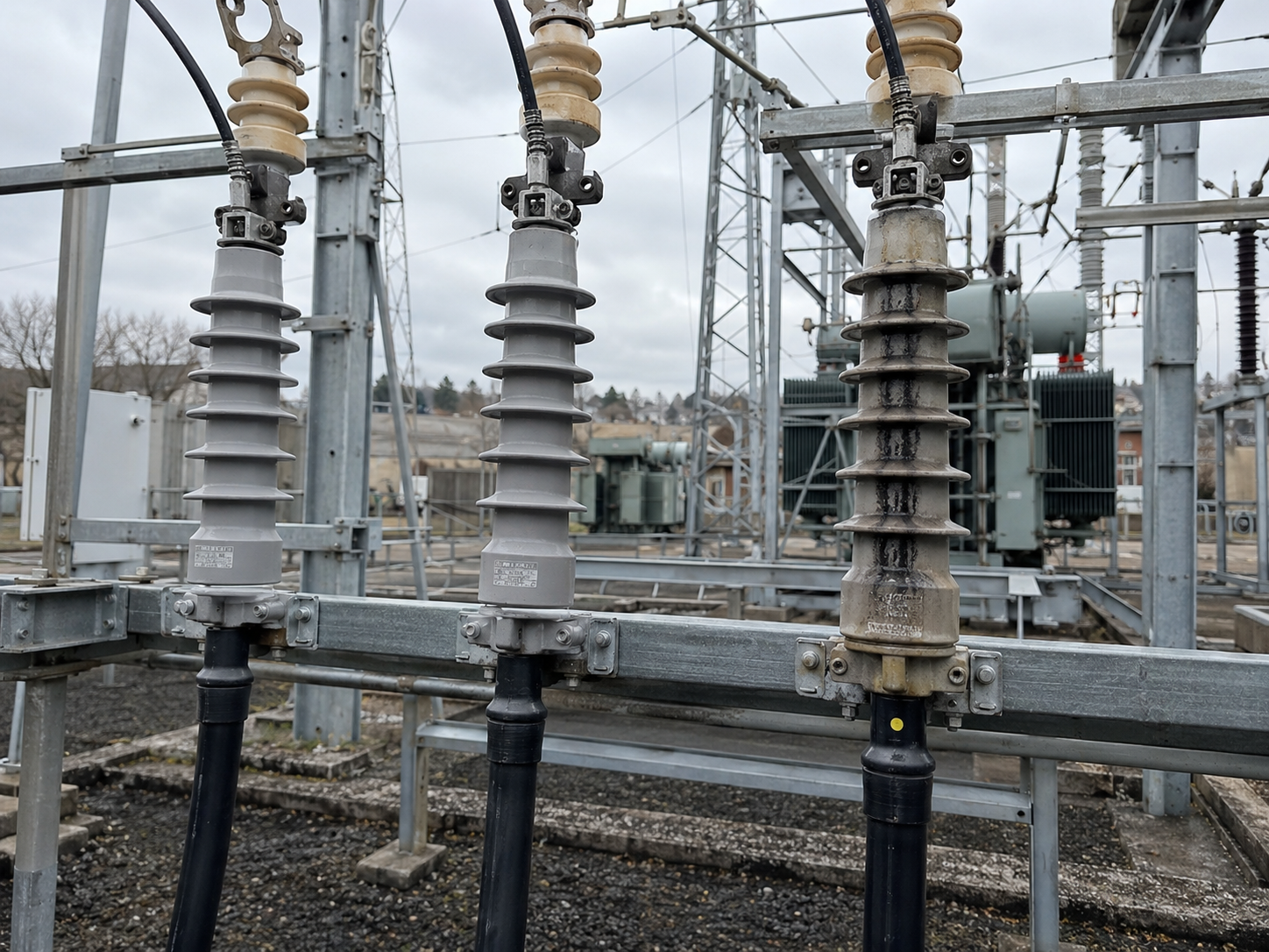
Surface tracking is an electrical insulation failure process where leakage current forms a conductive path across the surface of an insulating material. In MV and HV cable systems, surface tracking is most commonly discussed around cable terminations, where electrical stress, moisture, contamination and poor installation conditions can create a path for current to track across the insulation surface.
In simple terms, electrical tracking happens when the surface of an insulating material becomes progressively damaged and carbonised. Once a conductive track begins to form, it can grow across the insulation surface, increasing the risk of partial discharge, flashover, insulation breakdown and cable termination failure.
Surface tracking is a serious issue for 11kV, 33kV, 66kV and higher voltage cable terminations because the cable end is a point of high electrical stress. Correct termination selection, cable preparation, stress control, sealing, cleaning and installation practice are essential to reduce the risk of tracking and long-term failure.
Thorne & Derrick supply MV HV cable joints, terminations and connectors, including 3M cold shrink cable terminations, cable jointing tools, semi-con screen removal tools and cable preparation equipment for medium and high voltage power systems.
Quick Answer: What Is Surface Tracking?
Surface tracking is the formation of a conductive path across the surface of an insulating material. In electrical power systems, it can occur when moisture, contamination and electrical stress allow leakage current to flow over the insulation surface.
On MV and HV cable terminations, surface tracking can lead to partial discharge, flashover and eventual termination failure if the cause is not corrected. It is often associated with polluted environments, condensation, poor cable preparation, inadequate stress control, damaged insulation, poor sealing or unsuitable termination materials.
What Is Surface Tracking?
Surface tracking is a progressive insulation damage mechanism. It begins when electrical leakage current flows across the surface of an insulating material. Over time, the surface can become degraded, carbonised or contaminated enough to form a conductive track.
Once a track begins, current can continue to follow the damaged path. This can create heat, discharge activity, erosion and further carbonisation. If left untreated, the path can develop until the insulation can no longer withstand the electrical stress.
In MV and HV cable systems, tracking is particularly concerning because the voltage stress is high and the consequences of failure can be severe. A tracking failure at a termination can lead to outage, switchgear damage, cable accessory replacement, unplanned maintenance and safety risks.
Surface tracking is different from a simple surface mark. It is an electrical failure process that usually involves a combination of surface contamination, moisture and electric field stress.
Where Does Surface Tracking Happen?
Surface tracking can happen on many types of electrical insulation. It is most commonly associated with exposed or semi-exposed insulation surfaces where moisture and contamination can collect.
Typical locations include:
- MV cable terminations
- HV cable terminations
- Switchgear cable boxes
- Transformer cable boxes
- Outdoor terminations
- Porcelain and polymeric insulators
- Cable sealing ends
- Bushings and equipment interfaces
Indoor terminations can also suffer from tracking if there is condensation, dust, pollution, poor ventilation, thermal cycling, high humidity or contamination inside the cable box.
For cable accessory products, see HV cable joints, terminations and connectors.
What Causes Surface Tracking?
Surface tracking usually needs several conditions to be present at the same time. These are often described as electrical stress, moisture and contamination.
Tracking can also be accelerated by thermal cycling, vibration, poor enclosure design, inadequate creepage distance and repeated wetting and drying cycles.
Why Cable Terminations Are At Risk
MV and HV cable terminations are particularly vulnerable to surface tracking because they are the point where the cable insulation system ends and the cable connects to equipment.
Inside the cable, the electric field is controlled by the cable construction. At the end of the cable, the termination must recreate that control using stress control materials, insulation, sheds, sealing components and correct cable preparation.
If the termination is installed poorly, contamination is left on the insulation, the semi-con screen is cut incorrectly, or moisture reaches the surface, the termination may become more likely to suffer tracking.
Risk factors include:
- Incorrect semi-con screen removal
- Scratched or nicked cable insulation
- Poor stress control positioning
- Incorrect lug or connector installation
- Insufficient cleaning before assembly
- Moisture in the cable box
- Polluted or coastal environments
- Use of unsuitable termination technology
View cold shrink terminations for MV and HV cables.
Surface Tracking, Partial Discharge & Flashover
Surface tracking, partial discharge and flashover are related, but they are not the same thing.
A tracking path can encourage partial discharge activity, and severe tracking can eventually lead to flashover. Early identification and prevention are therefore important for MV and HV cable systems.
Creepage Distance & Insulation Surface Length
Creepage distance is the distance measured along the surface of an insulating material between conductive parts. In cable terminations and outdoor insulation systems, creepage distance is important because leakage current travels along the surface.
Polluted, wet or contaminated environments usually require greater surface distance and better anti-tracking performance. Outdoor terminations often use sheds or skirts to increase creepage distance and help manage water run-off.
Creepage distance matters because:
- Longer surface paths can reduce leakage current risk
- Sheds help increase the surface path length
- Pollution severity affects termination selection
- Coastal and industrial environments can increase contamination risk
- Incorrect indoor/outdoor selection may increase tracking risk
The correct termination should be selected according to voltage, environment, pollution level, cable construction and manufacturer guidance.
How To Reduce Surface Tracking Risk
Surface tracking risk can be reduced by selecting the correct cable accessory and installing it correctly.
Important prevention measures include:
- Use suitable cable terminations for the voltage, environment and cable construction.
- Prepare the cable accurately using correct semi-con and insulation stripping tools.
- Keep the installation clean during termination assembly.
- Avoid damaging the insulation with knives or unsuitable tooling.
- Control the electric field using correctly positioned stress control materials.
- Seal against moisture using the correct mastic, tubes, boots or termination components.
- Select anti-tracking materials for polluted, wet or outdoor locations.
- Inspect cable boxes and terminations for contamination, condensation or damage.
- Follow manufacturer installation instructions exactly.
A high-quality termination can still fail if it is poorly installed or exposed to unsuitable conditions.
Cold Shrink Terminations & Anti-Tracking Materials
Cold shrink terminations are widely used for MV and HV power cables because they are factory-expanded and installed without heat. The cold shrink body contracts around the prepared cable when the support core is removed.
Silicone cold shrink terminations are commonly used because silicone rubber can provide strong hydrophobic and anti-tracking performance. Hydrophobicity helps repel water, which can reduce the risk of continuous wet films forming across the termination surface.
This is important because surface moisture and contamination can contribute to leakage current and tracking. For polluted or outdoor environments, termination material selection becomes especially important.
Thorne & Derrick supply 3M cold shrink cable terminations for 11kV, 33kV and 66kV MV/HV cable systems, including indoor and outdoor termination applications.
Cable Preparation & Semi-Con Screen Removal
Poor cable preparation is one of the major causes of MV and HV accessory problems. The semi-conductive screen, insulation and cable sheath must be removed accurately without damaging the remaining cable layers.
The semi-con screen is especially important because it helps control the electric field around the cable insulation. During termination installation, the semi-con screen must be cut back cleanly to the correct dimension. A rough, damaged or contaminated cutback can increase stress and create a point where tracking or discharge activity may begin.
Good preparation requires:
- Correct semi-con screen removal tools
- Accurate cutback dimensions
- Clean insulation surface
- No knife scores or scratches
- Correct chamfering where required
- Correct installation of stress control materials
View semi-con screen removal tools and MV HV cable jointing tools for cable preparation.
Inspection, Testing & Warning Signs
Surface tracking may not always be visible in the early stages. However, there are warning signs that should be investigated by competent personnel.
Possible signs include:
- Black carbon tracking marks on insulation or termination surfaces.
- White powdering or surface erosion around the termination.
- Burn marks or localised heating.
- Cracking, splitting or swelling of termination materials.
- Condensation or water ingress inside cable boxes.
- Unusual smell, noise or visible discharge activity.
- Partial discharge test indications.
- Thermal imaging anomalies around cable terminations.
If tracking is suspected, the equipment should be assessed under the site’s electrical safety rules. MV and HV cable terminations should only be inspected, tested and worked on by trained and authorised personnel.
Common Surface Tracking Mistakes
Surface tracking risk often increases because small installation or maintenance issues are overlooked.
Common mistakes include:
- Using the wrong termination for the environment – indoor, outdoor, polluted and wet locations may require different designs.
- Poor cable cleaning – dust, grease, carbon, moisture or debris can create tracking paths.
- Damaging insulation during preparation – scratches can become electrical stress points.
- Incorrect semi-con cutback – rough or uneven edges can increase local stress.
- Poor sealing against moisture – water ingress can accelerate tracking.
- Ignoring cable box condensation – thermal cycling can lead to repeated moisture formation.
- Assuming a new termination cannot fail – poor installation can cause early-life failures.
- Not inspecting polluted environments – industrial and coastal sites may require more frequent checks.
- Using unsuitable tools – inaccurate preparation can create hidden defects.
Preventing tracking is usually easier, safer and cheaper than replacing failed terminations after flashover or breakdown.
Related MV HV Cable Products
Surface tracking is closely linked to cable termination selection, cable preparation and installation quality.
- HV Cable Joints, Terminations & Connectors – MV and HV cable accessories for power cable systems.
- 3M Cold Shrink Cable Terminations – 11kV, 33kV and 66kV cold shrink terminations for MV/HV cables.
- Nexans Cable Terminations – heat shrink and cold shrink MV/HV termination systems.
- Cold Shrink Terminations Guide – guide to MV/HV cold shrink cable terminations.
- Semi-Con Screen Removal Tools – tools for accurate MV/HV cable preparation.
- Cable Jointing Tools – cable preparation tools for joints, terminations and connectors.
- Semi-Conductive Layer On MV Cables – technical guide to cable screen layers and their purpose.
- 3M Terminations & Surface Tracking – Power & Cables article on surface tracking in MV terminations.
Surface Tracking FAQs
Q: What is surface tracking?
A: Surface tracking is the formation of a conductive path across the surface of an insulating material. It happens when leakage current, moisture, contamination and electrical stress progressively damage the insulation surface.
Q: What causes surface tracking on cable terminations?
A: Surface tracking on cable terminations is commonly caused by moisture, contamination, high electrical stress, poor cleaning, damaged insulation, poor semi-con cutback, inadequate sealing or unsuitable termination materials.
Q: Is surface tracking the same as partial discharge?
A: No. Surface tracking is the formation of a conductive path across insulation. Partial discharge is a localised electrical discharge within or across part of an insulation system. Tracking can encourage partial discharge and may eventually lead to flashover.
Q: Why are MV cable terminations at risk of tracking?
A: MV cable terminations are at risk because the cable end is an area of high electrical stress. Moisture, contamination, poor stress control or damaged insulation can allow leakage current to form tracking paths across the termination surface.
Q: What does tracking look like?
A: Tracking can appear as black carbon marks, surface erosion, burn marks, cracks, powdering or discoloured paths on insulation or termination surfaces. It should be investigated by competent electrical personnel.
Q: How can surface tracking be prevented?
A: Surface tracking risk can be reduced by selecting suitable terminations, preparing the cable correctly, cleaning the insulation surface, sealing against moisture, using anti-tracking materials and following manufacturer installation instructions.
Q: What is creepage distance?
A: Creepage distance is the distance measured along the surface of an insulating material between conductive parts. Longer creepage distance helps reduce the risk of leakage current and tracking in polluted or wet environments.
Q: Can poor semi-con screen removal cause tracking?
A: Poor semi-con screen removal can create rough edges, contamination, scratches or stress points on the insulation. This can increase the risk of discharge activity and tracking around MV and HV cable terminations.
Conclusion
Surface tracking is a progressive insulation failure process where a conductive path forms across the surface of an insulating material. In MV and HV cable systems, it is most often associated with cable terminations exposed to moisture, contamination and high electrical stress.
The risk of tracking can be reduced through correct termination selection, accurate cable preparation, clean installation, effective stress control, moisture sealing, anti-tracking materials and routine inspection.
Thorne & Derrick supply MV HV cable joints, terminations, connectors, 3M cold shrink terminations and cable jointing tools for medium and high voltage power cable systems, including 11kV, 33kV and 66kV cable installations.
Trefoil Cable Formation Explained
July 23rd, 2026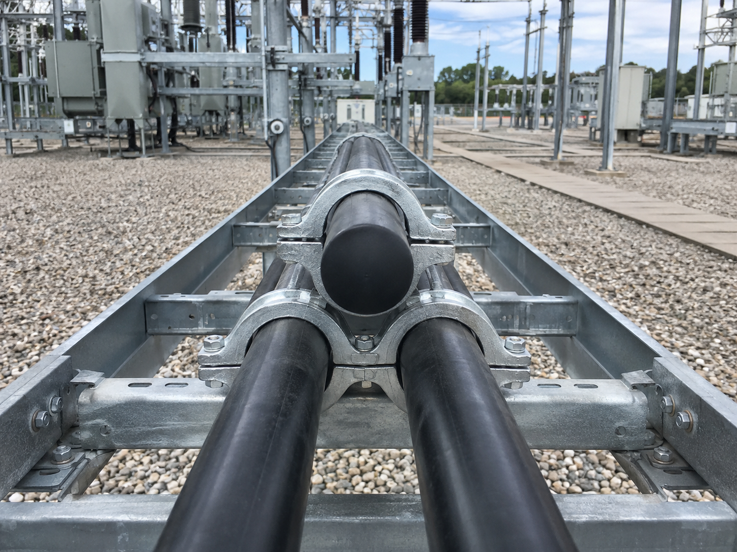
Trefoil cable formation is an installation method where three single core power cables are arranged together in a triangular, shamrock-style formation. Each cable normally represents one phase of a three-phase electrical circuit, and the three cables are held together using trefoil cable cleats or cable clamps.
Trefoil formation is commonly used for LV, MV and HV single core cable installations, including 600/1000V, 11kV, 33kV, 66kV and higher voltage power cable systems. It is used across substations, industrial power networks, renewable energy projects, data centres, utilities, rail infrastructure and electrical distribution systems.
The purpose of trefoil formation is not only neat cable management. It also helps manage magnetic effects, reduces cable spacing, supports short-circuit restraint and keeps the three phases correctly grouped along the cable route. When single core cables are installed in trefoil, they must be restrained with suitable cable cleats selected according to cable diameter, fault level, support structure, cleat spacing and project specification.
Thorne & Derrick supply trefoil cable cleats, LV MV HV cable cleats, Ellis Patents cleats, Prysmian BICON cleats and tested cable restraint systems for single, trefoil, quadrafoil and bundled power cable installations.
Quick Answer: What Is Trefoil Cable Formation?
Trefoil cable formation is the arrangement of three single core power cables in a triangular formation. The three cables normally represent the three phases of a three-phase circuit and are installed together using trefoil cable cleats.
Trefoil formation is commonly used for single core LV, MV and HV cables. It helps keep the phases grouped, reduces magnetic imbalance compared with widely spaced single cores, supports efficient cable installation and allows the cables to be restrained using tested cable cleats.
What Is Trefoil Cable Formation?
Trefoil cable formation is a method of installing three single core cables together so that the cable centres form a triangle. The term “trefoil” comes from the three-lobed shape created when the cables are grouped together.
In a three-phase circuit, the single core cables are usually arranged as:
- L1 / Phase A
- L2 / Phase B
- L3 / Phase C
The three phases are held together using a trefoil cable cleat. The cleat clamps around the three cables and fixes them to the cable ladder, tray, bracket, Unistrut, concrete surface or steelwork.
Trefoil formation is most common when the electrical design uses three single core cables instead of one multicore cable. This is often seen on larger power circuits where cable size, current rating, installation method, handling, bending radius or system design makes single core cables more practical.
Why Are Single Core Cables Installed In Trefoil?
Single core cables are installed in trefoil for several electrical and mechanical reasons.
The three phases of an AC circuit create magnetic fields around the cables. If single core cables are spaced too far apart or installed incorrectly, magnetic effects can increase losses, induce currents in nearby metallic components and create unwanted heating.
Trefoil formation helps keep the phases close together. This helps balance the magnetic fields produced by the three phase conductors and can reduce the risk of heating effects in nearby metalwork compared with poorly arranged single core cable routes.
Trefoil formation also helps:
- Keep the three phases grouped along the route
- Reduce the overall cable footprint
- Simplify cleating and restraint
- Improve cable route organisation
- Support short-circuit force restraint
- Maintain phase identification and circuit grouping
The exact formation should always follow the electrical design, cable manufacturer guidance and project specification.
Trefoil vs Flat Cable Formation
Single core cables are commonly installed in either trefoil formation or flat formation. Both methods can be correct, depending on the installation design.
Trefoil is often chosen where compact grouping and magnetic field balance are important. Flat formation may be used where the design needs greater cable spacing for thermal performance, specific route constraints or installation access.
Why Trefoil Cable Cleats Are Used
Trefoil cable cleats are used to clamp, support and restrain three single core cables installed in trefoil formation. They keep the cable group fixed to the support structure during normal service and during fault conditions.
Cable cleats are not just cable tidies. In power cable systems, they are safety-critical components. During a short circuit, very large electromagnetic forces can act between the cables. If the cleats are under-specified, poorly spaced or incorrectly installed, the cables may move violently and damage the installation.
Trefoil cable cleats help:
- Retain cables during short-circuit conditions
- Maintain phase grouping
- Support the cable weight
- Control cable movement
- Protect nearby equipment and structures
- Support compliance with project and standard requirements
Thorne & Derrick supply trefoil cable cleats for LV, MV and HV cable systems, including cleats for 11kV, 33kV and higher voltage applications.
Short-Circuit Forces & Cable Restraint
When a short circuit occurs, the current flowing through the cables can generate very high electromechanical forces. These forces can cause cables to move, twist, strike nearby equipment or break free from unsuitable supports.
The force depends on factors such as:
- Peak fault current
- Cable diameter
- Cable spacing
- Cable formation
- Cleat spacing
- Support structure strength
- Cable route changes and bends
This is why cable cleats should be selected using actual project fault data and cable dimensions. A cleat that physically fits the cable is not automatically suitable for the fault level.
For more detail, see the Power & Cables guide to IEC 61914 cable cleats and short-circuit protection.
IEC 61914 & Cable Cleat Testing
IEC 61914 is the international standard for cable cleats used in electrical installations. It covers important cable cleat performance requirements, including mechanical strength, short-circuit testing, impact, corrosion, UV resistance and other classification areas.
For trefoil cable installations, IEC 61914 is important because it helps prove that a cable cleat has been tested for the type of cable restraint duty it may face in service.
Cable cleat selection should consider:
- IEC 61914 classification
- Short-circuit test performance
- Peak withstand current
- Cleat material
- Cable diameter range
- Maximum recommended spacing
- Installation environment
- Support structure compatibility
Browse the Power & Cables cable cleats guide for more information about specification, types and standards.
Where Is Trefoil Formation Used?
Trefoil cable formation is used wherever three single core cables need to be installed as a three-phase power circuit.
Common applications include:
- LV power distribution – large single core 600/1000V cable circuits.
- 11kV and 33kV MV networks – substation, utility and industrial medium voltage cable routes.
- 66kV and 132kV HV circuits – transmission and grid infrastructure cable installations.
- Substations – transformer, switchgear and cable sealing end connections.
- Renewable energy projects – solar farms, wind farms, battery storage and grid connections.
- Data centres – high current power distribution and backup power circuits.
- Industrial sites – process plants, factories, utilities and large motors.
- Cable tunnels, trenches and risers – controlled cable support and containment routes.
Trefoil cleats may be installed onto ladder rack, cable tray, steelwork, concrete structures, Unistrut or dedicated support brackets depending on the route design.
How To Select Trefoil Cable Cleats
Selecting the correct trefoil cable cleat requires technical project information. The cleat must match the cable size, system duty and environment.
For detailed advice, see the complete range of cable cleats, clamps and hangers.
Common Trefoil Installation Mistakes
Trefoil cable installation mistakes can reduce safety, reliability and installation quality.
Common mistakes include:
- Using cable ties instead of tested cleats – cable ties are not suitable for restraining high short-circuit forces.
- Selecting cleats only by cable diameter – fault level and cleat spacing are also essential.
- Ignoring short-circuit forces – cables can move violently during fault conditions if not properly restrained.
- Incorrect cleat spacing – wide spacing may reduce restraint performance.
- Mixing cable phases incorrectly – the three phases should remain correctly grouped along the route.
- Poor support structure design – the ladder, tray or steelwork must be strong enough for the forces involved.
- Ignoring bend and route changes – bends and vertical runs may require closer cleating or additional support.
- Using unsuitable cleat materials – corrosion, UV, chemical or fire exposure can affect material choice.
- Not checking IEC 61914 test data – cleat performance should be proven, not assumed.
Correct trefoil installation is a combination of cable design, fault calculations, cleat selection, cleat spacing and good installation practice.
Related Trefoil Cable & Cable Cleat Products
Trefoil cable formation is part of a wider single core cable and cable cleat system.
- Trefoil Cable Cleats – cleats for retaining three single core cables in trefoil formation.
- Cable Cleats, Clamps & Hangers – cable restraint products for LV, MV and HV installations.
- Ellis Patents Trefoil Cable Cleats – trefoil cleats for cable restraint and short-circuit protection.
- Ellis Alpha Trefoil Cable Cleats – aluminium trefoil cable cleats for LV, MV and HV applications.
- Ellis Trident Cable Cleats – cable cleats for LV, MV and HV power cable systems in trefoil installation.
- Cable Cleats Guide – guide to cable cleat specification, types and standards.
- IEC 61914 Cable Cleats – guide to cable cleat short-circuit protection and IEC 61914.
- Single Core XLPE Cables – single core power cables commonly restrained in trefoil formation.
Trefoil Cable FAQs
Q: What is trefoil cable formation?
A: Trefoil cable formation is the arrangement of three single core power cables in a triangular formation. The three cables usually represent the three phases of a three-phase circuit and are restrained using trefoil cable cleats.
Q: Why are cables installed in trefoil?
A: Cables are installed in trefoil to group the three phases closely together, help manage magnetic effects, reduce cable route footprint and allow the cables to be restrained using tested trefoil cable cleats.
Q: What are trefoil cable cleats?
A: Trefoil cable cleats are cable clamps designed to hold three single core cables together in trefoil formation. They support the cable weight and help restrain the cables during short-circuit conditions.
Q: What is the difference between trefoil and flat formation?
A: Trefoil formation groups three single core cables in a triangular arrangement. Flat formation installs the three cables side by side in a row. The correct choice depends on current rating, cable spacing, fault level, thermal performance and route design.
Q: Are cable ties suitable for trefoil cables?
A: Cable ties are not suitable for restraining high short-circuit forces in power cable installations. Trefoil cable cleats should be selected using cable diameter, fault current, cleat spacing and tested performance data.
Q: What is IEC 61914?
A: IEC 61914 is the international standard for cable cleats used in electrical installations. It covers performance requirements including mechanical strength, short-circuit testing, impact, corrosion and environmental classification.
Q: How do you choose trefoil cable cleat spacing?
A: Trefoil cable cleat spacing should be based on cable diameter, fault current, cable route, cleat test data, support structure and manufacturer guidance. It should not be guessed or based only on visual cable support.
Q: Where is trefoil cable formation used?
A: Trefoil cable formation is used in LV, MV and HV power cable systems, including substations, cable tunnels, ladders, trays, risers, utilities, renewables, data centres and industrial power networks.
Conclusion
Trefoil cable formation is a common method for installing three single core power cables in a three-phase circuit. The cables are arranged in a triangular formation and restrained using trefoil cable cleats.
Trefoil formation helps keep the phases grouped, supports magnetic field balance, reduces cable route footprint and allows the cables to be restrained against short-circuit forces. Correct cleat selection is essential, especially for LV, MV and HV power systems where fault levels can be high.
Trefoil cable cleats should be selected using cable diameter, formation, short-circuit current, cleat spacing, installation environment, support structure and IEC 61914 test data.
Thorne & Derrick supply trefoil cable cleats, cable clamps and cable cleat systems for LV, MV, HV and EHV power cable installations, including Ellis Patents, Prysmian BICON and other tested cable restraint solutions.
Earth Mats, Earth Tape & Portable Earthing
July 23rd, 2026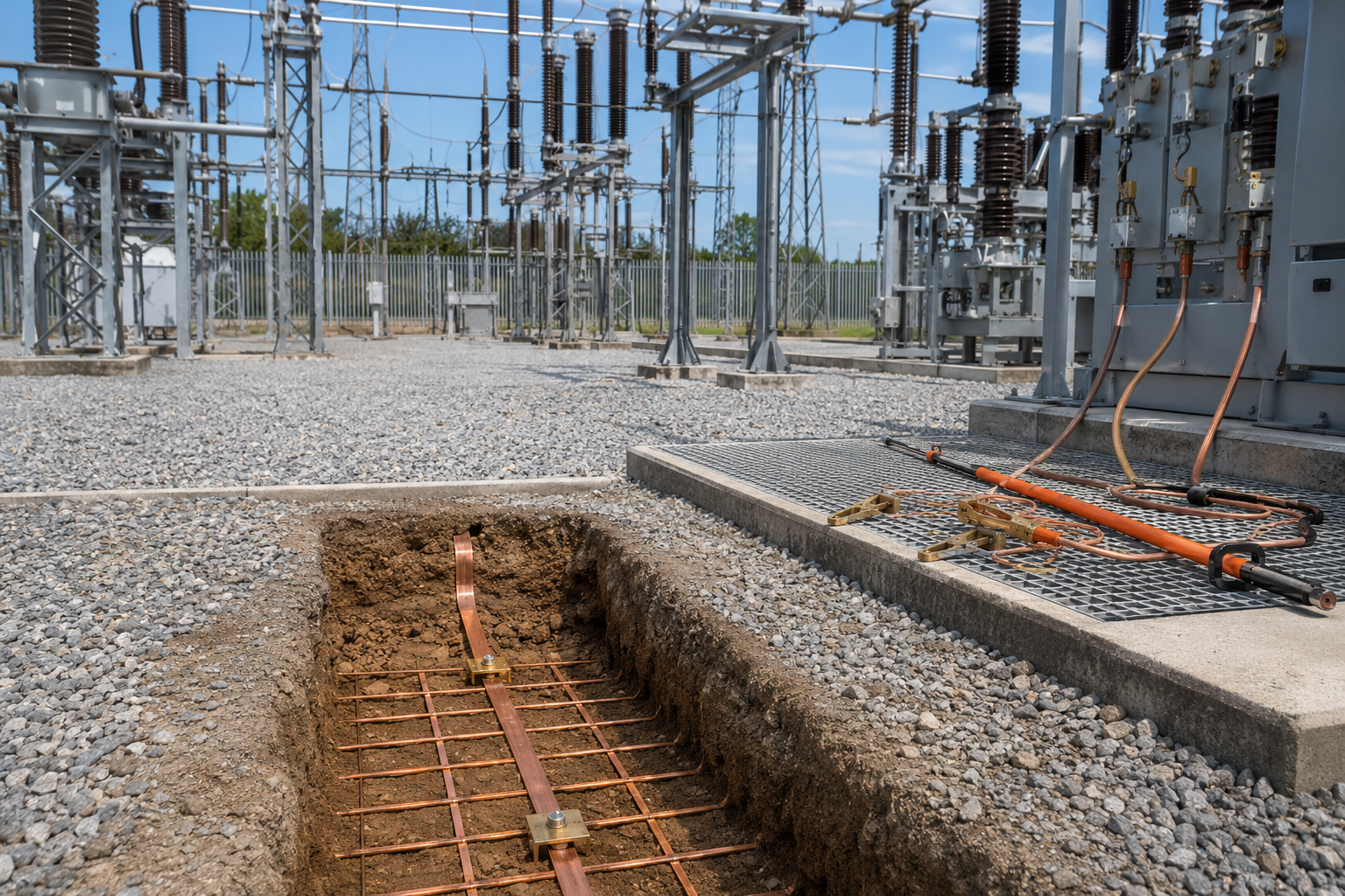
Earth mats, earth tape and portable earthing devices all form part of electrical earthing and safety systems, but they are not the same thing. Some are permanent components buried or fixed into an earthing system, while others are temporary safety devices used during maintenance, isolation and work on electrical equipment.
In LV, MV and HV electrical networks, earthing is essential for safety, fault current control, equipment bonding, lightning protection and reliable operation of electrical infrastructure. Correctly specified earthing systems help manage fault currents, reduce dangerous touch and step voltages, bond metallic structures and provide a route for electrical energy to return safely to earth.
Earth mats and copper earth tape are normally used as part of a fixed earthing system. Portable earthing kits are temporary short-circuiting and earthing devices used by authorised personnel after isolation to help make electrical equipment safe to work on.
Thorne & Derrick supply earth tapes, rods, bars and copper earthing products, copper earth mats, copper earth tape and portable earthing kits for LV, MV and HV electrical networks, substations, overhead lines, power cables and industrial power systems.
Quick Answer: Earth Mats, Earth Tape & Portable Earthing
Earth mats are copper earthing electrodes used to help reduce step and touch voltage risks, especially around substations, switchrooms and high voltage equipment. Copper earth tape is a flat copper conductor used to connect earthing electrodes, earth bars, structures and electrical equipment. Portable earthing devices are temporary short-circuiting and earthing kits used after isolation to help protect authorised workers during maintenance.
The key difference is that earth mats and earth tape are normally part of a fixed, permanent earthing system. Portable earthing kits are temporary safety equipment applied, tested and removed by trained personnel as part of safe working procedures.
What Is Electrical Earthing?
Electrical earthing is the process of connecting electrical equipment, structures, cable systems or lightning protection systems to earth using conductors, electrodes and bonding connections. The purpose is to provide a controlled path for fault current, lightning current or unwanted electrical energy.
Earthing systems help:
- Protect people by reducing dangerous touch and step voltage risks.
- Protect equipment by providing a return path for fault current.
- Support protective devices by helping fault current flow so protection can operate.
- Bond metallic structures to reduce voltage differences between exposed conductive parts.
- Support lightning protection systems by providing a route for lightning current to dissipate into earth.
- Improve network safety in substations, industrial facilities and power distribution systems.
In practical terms, earthing systems are made up of components such as copper earth tape, earth rods, earth mats, earth plates, earth bars, clamps, conductors, inspection pits, Marconite and Bentonite.
What Are Earth Mats?
An earth mat is an earthing electrode, often manufactured from copper tape in a lattice or solid arrangement, used to improve earthing performance and help control touch and step voltage risks.
Earth mats are commonly used around:
- Substation switchgear
- Transformer areas
- High voltage switching points
- Outdoor electrical structures
- Street works and compact earthing installations
- Lightning protection electrodes
- Areas where potential grading is required
Power & Cables explains that earth mats manufactured from high conductivity copper tape help reduce the danger of exposure to high step and touch voltages for substation and authorised personnel working on high voltage switching.
View copper earth mats for substation, utility and electrical infrastructure applications.
What Is Copper Earth Tape?
Copper earth tape is a flat copper conductor used to connect earthing electrodes, electrical equipment, structural steelwork, earth bars and lightning protection systems.
It is widely used because copper provides high conductivity and can be installed in trenches, along structures, around substations and as part of buried earth grids. Earth tape can be supplied in different widths and thicknesses depending on the required current carrying capacity, mechanical strength and project specification.
Typical uses of copper earth tape include:
- Buried earth grids
- Substation earthing systems
- Lightning protection down conductor connections
- Equipment bonding
- Transformer and switchgear earthing
- Earth rod interconnections
- Connections to earth bars and test links
Power & Cables supplies bare and covered copper earth tapes for LV, MV and HV substations, buildings and electrical infrastructure. :contentReference[oaicite:3]{index=3} Wallis copper earth tapes are also listed for earthing and lightning protection applications.
What Are Portable Earthing Devices?
Portable earthing devices are temporary earthing and short-circuiting kits used by authorised electrical workers after equipment has been isolated, tested and confirmed safe for the application of earths.
They are used to help protect workers against:
- Accidental re-energisation
- Induced voltages
- Stored electrical energy
- Unexpected backfeed
- Fault current during maintenance conditions
Portable earthing kits typically include clamps, insulated earth leads, short-circuiting leads, operating sticks and connection accessories. CATU portable earthing and short-circuiting kits are available with choices of earth clamps for live end and earth end applications, jumper clamps for LV switchboards and overhead line clamps.
Power & Cables also lists portable earthing leads in kit form for substations, including field earths, trailing earths, bridging earths, circuit main earths, drain earths and NSI24 kits.
Fixed Earthing vs Portable Earthing
Fixed earthing and portable earthing are often confused, but they have different purposes.
Both are important. A fixed earthing system does not remove the need for portable earthing procedures, and portable earthing equipment does not replace a properly designed permanent earth grid.
Substation Earthing Applications
Substations require carefully designed earthing systems because fault current levels can be high and personnel may need to operate or maintain equipment close to metallic structures, switchgear, transformers and cable systems.
Earthing products used in substations may include:
- Copper earth tape for buried earth grids and bonding.
- Copper earth mats for potential grading and localised step/touch voltage control.
- Earth rods to improve connection to the general mass of earth.
- Earth bars for common earth termination points.
- Earth clamps and connectors for conductor connections.
- Marconite or Bentonite where ground conditions require earthing enhancement.
- Portable earthing kits for safe maintenance procedures.
Copper lattice earth mats are used in high fault current and step potential avoidance applications such as high voltage substations and switchrooms.
For wider earthing products, see earth tapes, rods, bars and copper earthing accessories.
Earth Rods, Earth Bars & Accessories
Earth mats and earth tape are normally used alongside other earthing products. A complete earthing system may include several different components.
Power & Cables states that earth rods are used to provide the interface to ground in all soil conditions for overhead and underground electricity distribution and transmission networks, including low, medium and high voltage substations, towers and power distribution applications.
Earth bars are used for terminating cable lugs or earth tape connections and are commonly manufactured from high-conductivity copper bar.
Marconite, Bentonite & Soil Conditions
The performance of an earthing system depends heavily on the surrounding ground conditions. Dry, rocky, sandy or high-resistivity soil may make it harder to achieve the required earth resistance using rods and tape alone.
Earthing enhancement materials can help improve electrode contact with the surrounding soil.
- Marconite is a conductive aggregate used with cement and water to form conductive concrete around earth electrodes.
- Bentonite is a clay-based earthing compound used as backfill around electrodes.
Marconite and Bentonite should not be treated as the same product. The correct selection depends on the earthing design, soil resistivity, resistance target, installation method and long-term performance requirements.
For more detail, see the Power & Cables guide to Marconite earthing.
How To Select Earthing Products
Earthing products should be selected as part of a complete electrical earthing design. The right products depend on the system voltage, fault level, soil conditions, resistance target, location, network type and maintenance requirements.
For portable earthing kits, selection should also consider the equipment type, voltage level, clamp type, connection points, short-circuit rating, lead length and approved safe working procedure.
Common Earthing Mistakes
Earthing errors can create serious safety risks, especially around substations, overhead lines, switchgear and high fault current electrical systems.
Common mistakes include:
- Confusing fixed earthing with portable earthing – permanent electrodes and temporary safety earths have different purposes.
- Ignoring soil resistivity – earthing design should be based on site conditions, not assumptions.
- Using undersized conductors – copper tape and conductors must be suitable for the required fault current and duration.
- Forgetting step and touch voltage – low earth resistance alone does not always guarantee personnel safety.
- Poor connection quality – loose, corroded or unsuitable connections can reduce earthing performance.
- Failing to test the system – earth resistance and continuity testing are essential after installation.
- Selecting portable earths without fault rating – portable earthing kits must be selected for the fault level and application.
- Using the wrong clamp type – clamp design must suit the connection point, such as busbar, conductor, earth tape or switchgear point.
- Not maintaining portable earthing equipment – leads, clamps and sticks should be inspected and maintained according to site procedures.
Earthing should always be designed, installed, tested and maintained by competent personnel.
Related Earthing & Electrical Safety Products
Earthing products are usually specified as part of a complete earthing, bonding and electrical safety system.
- Earth Tapes, Rods, Bars & Copper Earthing Products – full range of fixed earthing products for LV, MV and HV systems.
- Copper Earth Mats – earth mats for substation, switchroom and potential grading applications.
- Copper Earth Tape – bare and covered copper tape for earthing and lightning protection.
- Earth Rods – electrodes for overhead and underground power networks.
- Earth Bars – copper bars for earthing terminations and bonding connections.
- Portable Earthing Kits – temporary earthing and short-circuiting kits for substations, overhead lines and cable systems.
- Marconite – conductive concrete aggregate for low resistance earthing systems.
- Bentonite – earthing compound for electrode backfill applications.
- AN Wallis Earthing & Lightning Protection – copper earth rods, tapes, bars, mats, clamps and lightning protection products.
Earthing FAQs
Q: What is an earth mat?
A: An earth mat is a copper earthing electrode, often made in a lattice or solid arrangement, used to improve earthing performance and help reduce step and touch voltage risks around electrical equipment.
Q: What is copper earth tape used for?
A: Copper earth tape is used to connect earthing electrodes, earth bars, structural steelwork, electrical equipment and lightning protection systems. It is commonly used in buried earth grids and substation earthing systems.
Q: What is a portable earthing device?
A: A portable earthing device is temporary electrical safety equipment used to earth and short-circuit isolated electrical equipment during maintenance. It usually includes clamps, insulated leads and connection accessories.
Q: What is the difference between fixed earthing and portable earthing?
A: Fixed earthing is the permanent earthing system installed as part of the electrical infrastructure. Portable earthing is temporary safety equipment applied by authorised personnel during isolation and maintenance work.
Q: Where are earth mats used?
A: Earth mats are commonly used around substations, switchrooms, transformer areas, high voltage switching points, outdoor electrical structures and locations where potential grading is required.
Q: Are earth mats and earth rods the same?
A: No. An earth rod is a vertical or angled electrode driven or installed into the ground. An earth mat is a wider copper electrode arrangement, often lattice-based, used for potential grading and earthing performance.
Q: When is portable earthing used?
A: Portable earthing is used during electrical maintenance and isolation procedures after equipment has been isolated and proved safe for the application of earths. It should only be used by authorised and trained personnel.
Q: What products are used in an earthing system?
A: Earthing systems can include copper earth tape, earth rods, earth mats, earth bars, clamps, connectors, inspection pits, Marconite, Bentonite and portable earthing equipment depending on the application.
Conclusion
Earth mats, earth tape and portable earthing devices are all important parts of electrical earthing and safety, but each product has a different role.
Earth mats and copper earth tape are used as part of permanent earthing systems for substations, buildings, lightning protection, power networks and electrical infrastructure. Portable earthing kits are temporary safety devices used by authorised personnel during maintenance, isolation and work on electrical systems.
Correct selection depends on the application, voltage level, fault current, soil conditions, step and touch voltage requirements, connection points, testing requirements and safe working procedure.
Thorne & Derrick supply earth mats, copper earth tape, earth rods, earth bars, Marconite, Bentonite and portable earthing kits for LV, MV and HV electrical networks, substations, overhead lines, underground cables, lightning protection and industrial power systems.


