

Blog
Understanding Battery Energy Storage Systems (BESS) and Power Arbitrage By SPE Electrical Ltd
June 15th, 2021

This article has been republished with the kind permission of SPE Electrical Ltd.
SPE Electrical Ltd
SPE Electrical are based in Dorset, in the South West, but serve the whole of the UK as well as many international clients.
The company was created in early 2006, in recognition of the rapidly expanding infrastructure and energy sectors, and the associated need for specialist HV consultancy services. To date their power system consultants have undertaken a wide range of studies for a variety of local, national and international clients.
The company specialise in all aspects of design, analysis and consultancy that relate to large power system and have design experience from low voltage to 400kV, and covers industries as diverse as renewable power to water treatment plants. SPE Electrical Ltd are also well versed in international design standards and practices such as IEC, ANSI, IEEE, NEC and NFPA, and their engineers have worked on projects all around the globe.
Battery Energy Storage Systems – Power Arbitrage
Part 1: Introduction
Battery Energy Storage Schemes are very versatile plants and can be used for a number of different services, depending on the plant design and aims; this can include services such as power arbitrage, voltage control, and the new Dynamic Containment (DC) service which replaces the old Enhanced Frequency Response (EFR) service. BESS units can also be used as a power balancing service, to meet shortfalls in power, to limit disturbances from the grid during transient switching events, where a plant has large dynamics loads, such as big motors and generators that switch in and out frequently.
At SPE we have found that many developers are keen to add battery storage systems into their existing projects, but are often unsure exactly how the battery will be used. This leads to the dilemma of trying to design a system that will be flexible enough to allow future revenue streams, without pre-investing for expensive system upgrades.
This first post gives a simple guide to explain the basic ideas of how a BESS works and looks at their role in providing power arbitrage.
Part 2: BESS Basics
Before we get into the specifics, it is worth covering a couple of basic ideas of what a BESS is and how it operates. First off, the term BESS is generic name for an electronic Power Conversion System (PCS) i.e. inverter, coupled with some form of battery. From the DNO and TSO perspective the battery doesn’t actually matter too much, and it is the PCS that is really of interest.
The battery can be anything from old car batteries, to modern li-Ion batteries, or more advanced cryo-batteries or flow batteries.
The battery type just determines how much energy can be stored and how quickly it can be converted from chemical form to electrical energy.
Second, a simple concept that is often misunderstood is the difference between power (MW) and energy (MWh). A BESS rated at 1MW & 1MWh can provide 1MW for an hour, of 0.5MW for 2 hours, or 0.25MW for 4 hours etc. but it can never provide more than 1MW, because this limit is imposed by the inverter rating and system design. From the DNO perspective the amount of MW is important, as this governs the main power flows in their network.
This leads to our third point, which is that of power swings. Simple MW flow is easy to understand from DNOs heat maps, but the ability of the DNO network to cope with large power swings is much less clear and usually needs some analysis.
For power swing, we are referring to the speed at which the BESS needs to change from import to export and vice versa. For power arbitrage this is very slow and doesn’t cause a significant power swing, but for fast response services like DC, the power swing can be significant with a 50MW BESS, potentially going from full export to full import in 1s, giving a 100MW/s power swing – which would challenge the most robust of power systems. This is why the G99 forms ask for the ramp rate of the BESS. This is bit of a tricky area, and often a major constraint, which we will go through in another post.
Our third point is that a BESS can provide reactive power as well as providing active power, and importantly it can provide reactive power at the same time, which is useful for regulating voltage on the DNO network. Provided the BESS is correctly sized, it could easily provide 20MW of active power and 20MVAr of reactive power.
So, when preparing a grid application for a BESS it is important to understand what services we are hoping to provide to the system and what the local limitations are.
The DNO or National Grid, typically want to know the MW capacity of the site, and the worst-case power swing as well as any reactive power flow capability, as these are what will affect their system behaviour and responses, but are not usually that interested in the MWh rating of the system.
Part 3: Power Arbitrage
The power arbitrage service of a BESS is technically and commercially the simplest concept for battery storage. It is based on the simple premise of absorbing energy when it power is cheap, such as at night or when there is excess power from CHP or solar array, and then discharging the battery during peak load times. The benefit of such an approach allows what is known as load demand curve shifting, where the excess power from renewables (often solar) is stored at high production times / low demand then discharged at low production times / peak demand.
This has two main benefits. Firstly, and depending on the profile, high tariff electricity costs can be avoided, and a flat charging profile created. Secondly, it means that the size of the grid connection can potentially be reduced, although one needs to consider what happens if there was a shortfall in the surplus power i.e. a very cloud day, if the surplus comes from a Solar PV array.
The revenue streams here are obviously limited to the cost of energy creation and storage at cheap times, compared to the cost of energy during high tariff times, and is based on the concept of peak shifting the energy demand, so that it is balanced more evenly across a 24 hour (or whatever other timeframe). In the authors opinion, this is the ‘holy grail’ of most BESS units and The System Operators (TSO), an electrical system demand that is predictable, and therefore easy to plant and dispatch. In practice to achieve, this the BESS has to be cheap and robust enough to store and dispatch energy as needed, and when is most economic to do so.
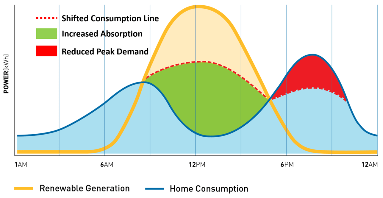
Figure 1: Diagram Showing Power Arbitrage Concept
With power arbitrage, the charge and discharge of the BESS is usually very slow, and this will not overly stress the host electrical system or the DNO system. From a design point of view, compliance with the ENA P28/2 standard is not usually an issue, but a large battery systems can contribute significantly to the system harmonics and voltage flicker due to the power electronics operation, which usually needs some careful analysis to ensure compliance.
A less obvious use of a BESS is using it as a power store to support starting and operation of a heavy consumer of power. Let us say for example you have a heavy industrial plant that you want to add a new 10MW motor to. Starting these motors is always a complex process, but fortunately ones that a Variable Speed Drive solves easily, but what happens if your grid supply to the DNO is maxed out and an upgrade will cost millions. Simple(ish), you install a BESS and charge it up overnight, then discharge it when the new drive needs to operate. The DNO does not see any additional power demand and no network upgrades are needed.
Part 4: Applications – Power Arbitrage & Balancing in a Water Treatment Works (WTW)
For an application example, let us consider an example of a Water Treatment Works (WTW) that is hoping to achieve carbon neutral status within the next 5 years. WTW sites are interesting ones to study, as they tend to have a mix of large varying loads such as pumps and compressors, and plenty of space to install Solar PV and a BESS and carry out the tie-ins between the new and existing plant. It should be noted that for our analysis, the site type doesn’t really matter as the principles are the same.
So how does power arbitrage work with a battery storage system work? This is best understood with an example. First, we start with the basic premise, that the plant owner has assessed their DNO connection and there are no problem and second that site has enough space to install a fair sized Solar PV array of 5-10 MW. Next, we look at the site power consumption, this is usually very dynamic, but lets pretend for a moment, that we can simplify things a bit and say they have an average steady state consumption during the day of 2MW, and at night-time it drops to 0.5MW. Our basic specification might look something like this:
- Space to install 5-10MW Solar PV array.
- Available HV point for tie-in.
- Desire to achieve full carbon neutral operation.
- Site load profile is simplified to a consistent value of:
- 2 MW approximately constant load between 8am and 7pm (11 hours) = 22MWh
- 5MW constant load between 7pm and 8 am (13 hours) = 6.5MWh
Simple deployment of a solar PV scheme would certainly help the asset owner, as the power produced by the Solar PV would offset the power consumption of the WTW by a significant margin. However, the problem would be that either the Solar PV would be oversized and during peak daylight hours would be exporting power, or it would be undersized, and not fully offset the power demand, and in both cases the night-time power demand would still be needed. This presents a dilemma for the asset owner, as neither scheme meets the objectives, but by adding a BESS into the mix, we can possible meet all the target goals.
Next, let’s do bit of basic maths to see what works, to calculate average any usage, energy storage capacity and so on. This can be done in a number of ways, depending on the level of sophistication desired, at the most basic, a simple Excel and graphical model can be generated of the load and generation profiles, but it is relatively easy to create more advanced mathematical models of the system, using various integration methods and piecewise linear functions, or directly in simulation package like Matlab. For the purpose of this post we will go for an easy Excel approach.
In the below diagram we can see a simplified power generation diagram shown in block format for the power generation (green), power demand (red), excess PV discharged into the BESS (blue) and power discharged from the BESS (yellow).
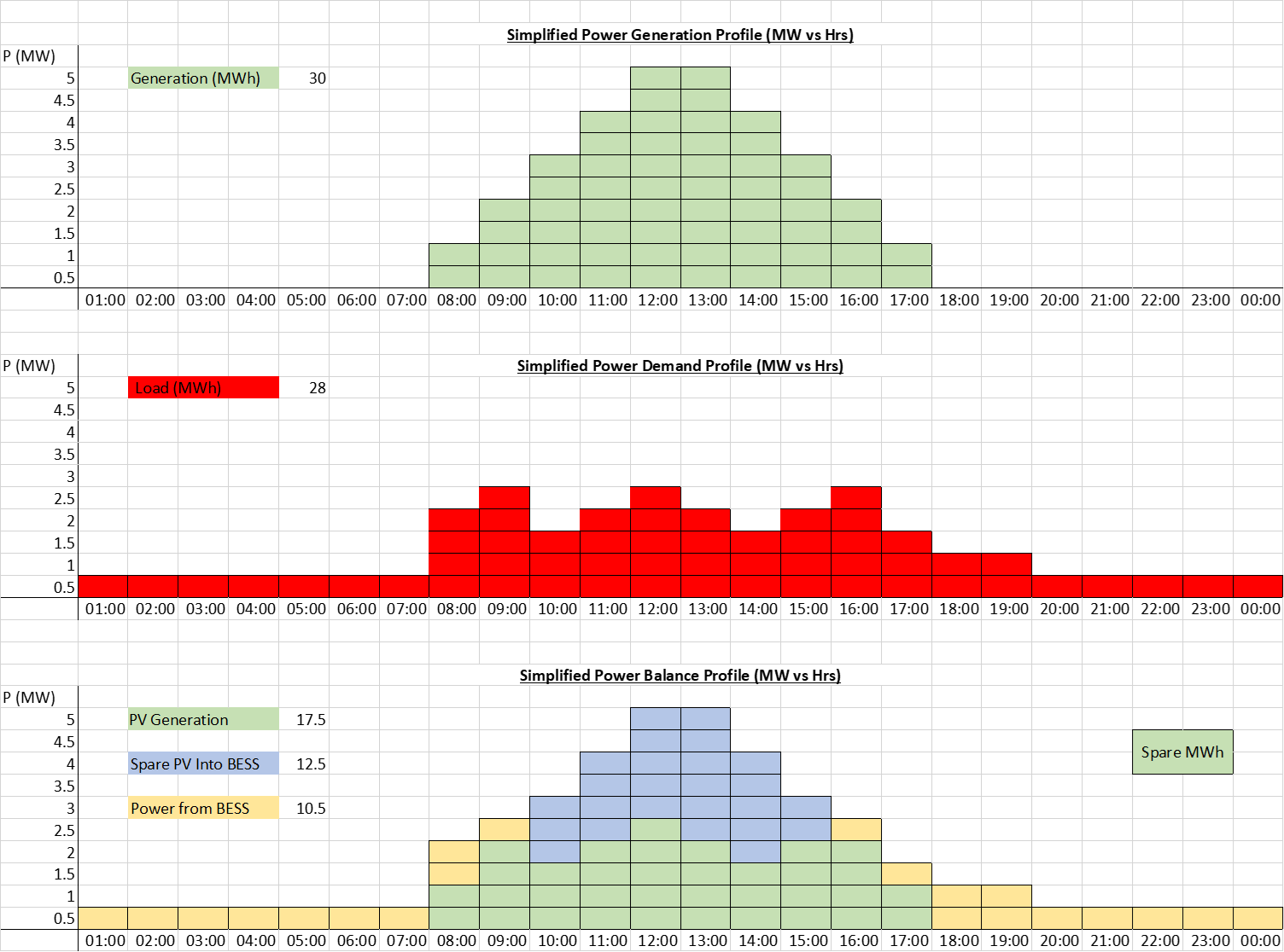
Figure 2: Simplified Block Diagram Showing Power Arbitrage Calculation
From the above plots we can see that we get a pretty good power balance, with around 2MWh spare capacity from the Solar PV system, which we can account for with intermittency, shading and other losses. We do can do some more simple maths and we can roughly dimension our PCS and battery size, as follows:
- The solar PV is sized to give a peak output of 5MWac.
- The battery PCS size has to be equal to the largest difference between the plant demand and the solar output. This occurs in the evening when power demand is still high and the solar output has fallen to near zero . I.e so the delta is 1 MW.
- We can see from the above that we need the BESS to be able to deliver 10.5 MWh.
- Our final design is therefore a 5 MW PV array coupled with a 1 MW BESS with a 10.5 MWh energy store.
Part 5: Summary – Power Arbitrage
The above is obviously very simple analysis, representing a simple Solar PV curve, and not accounting for probability and differing irradiance levels during the day and seasons. Likewise, the load is likely to significantly more variable than the simplified model shown. The thing to remember here, is that the post just shows a simple model for demonstration purposes, to show a principle of how a system could be made to work.
In practice, it is usually not economic to design a Solar PV and BESS system that achieves full carbon offset, because of the inherent probabilistic values in the irradiance levels. However, with some careful analysis and a bit of time, a Solar PV and BESS can go along way to meeting this target. The above example is for a WTW but would work just as well, for a large factory, or country estate. Of course, adding in a BESS to a brownfield site is never quite that simple, so it is usually necessary to carry out some surveys, and identify if the equipment is suitably rated for the increased duty and then identify the necessary tie in location.
It should also of course be noted that we have considered Solar PV and a battery storage solution here, but the principle applies to any intermittent renewable, such as wind power or wave power and any other storage technology, such as hydro, compressed air / gas etc. One final thing we can do with the new system, is to run the Solar and BESS at a slightly lagging power factor (producing MVArs) so the site is held at unity PF and even greater savings are achieved. If you would like to discuss your project requirements, please get in touch.
THORNE & DERRICK
Thorne & Derrick are national distributors of LV, MV & HV Cable Installation, Jointing, Substation & Electrical Equipment – servicing businesses involved in cabling, jointing, substation, earthing, overhead line and electrical construction at LV, 11kV, 33kV, 66kV and EHV. Supplying a complete range of power cable accessories to support the installation and maintenance of low/medium and high voltage power systems:
- Slip-on Cable Terminations
- Cold-shrink Cable Terminations
- Heat-shrink Cable Terminations
- Cable Joints – Heat & Cold-shrink
- Separable Connectors (Euromold)
- Surge Arresters & Switchgear/Transformer Bushings
Key Product Categories: Duct Seals | Cable Cleats | Cable Glands | Electrical Safety | Arc Flash Protection | Cable Jointing Tools | Cable Pulling | Earthing | Feeder Pillars | Cable Joints LV | Joints & Terminations MV HV

Earth Bars | High Specification Copper Earth Bars for Lightning Protection Systems
June 15th, 2021
Manufactured by AN Wallis | Distributed by Thorne & Derrick
Earth Bars
-
uploaded by Chris Dodds | Thorne & Derrick Sales + Marketing Manager
Copper Earth Bars for Lightning Protection Systems
Earth bars are an integral part of an Electrical oBuilding Services or Substation technical specification for earthing and bonding; they provide a convenient common earth point for the infrastructure. It is critical copper earth bars provide long lasting, high quality earthing capable of enduring any potential dangerous fault currents.
Main earthing bars provide a recognised earth connection/ reference point and allow the local substation earth resistance to be measured using a clamp meter.
Thorne & Derrick and AN Wallis are aware of the crucial role of an Earth Bar which is why they manufacture high quality, affordable earth bars that are designed and tested to all relevant standards – manufactured from hard drawn copper bar to BS EN 13601 and tested to BS EN 62561-1 Class H.
- Earthing bars can be tinned and bases powder coated to improve corrosion resistance
- Bars are pre-drilled with cable connection holes with optional threads for installation ease
- Manufactured from highest conductivity and quality copper to British Standards
- Full range of standard, single and twin link types for LV, MV & HV switchroom/substations
- Customised to suit the earthing requirements of your project on short lead times
Customer Service
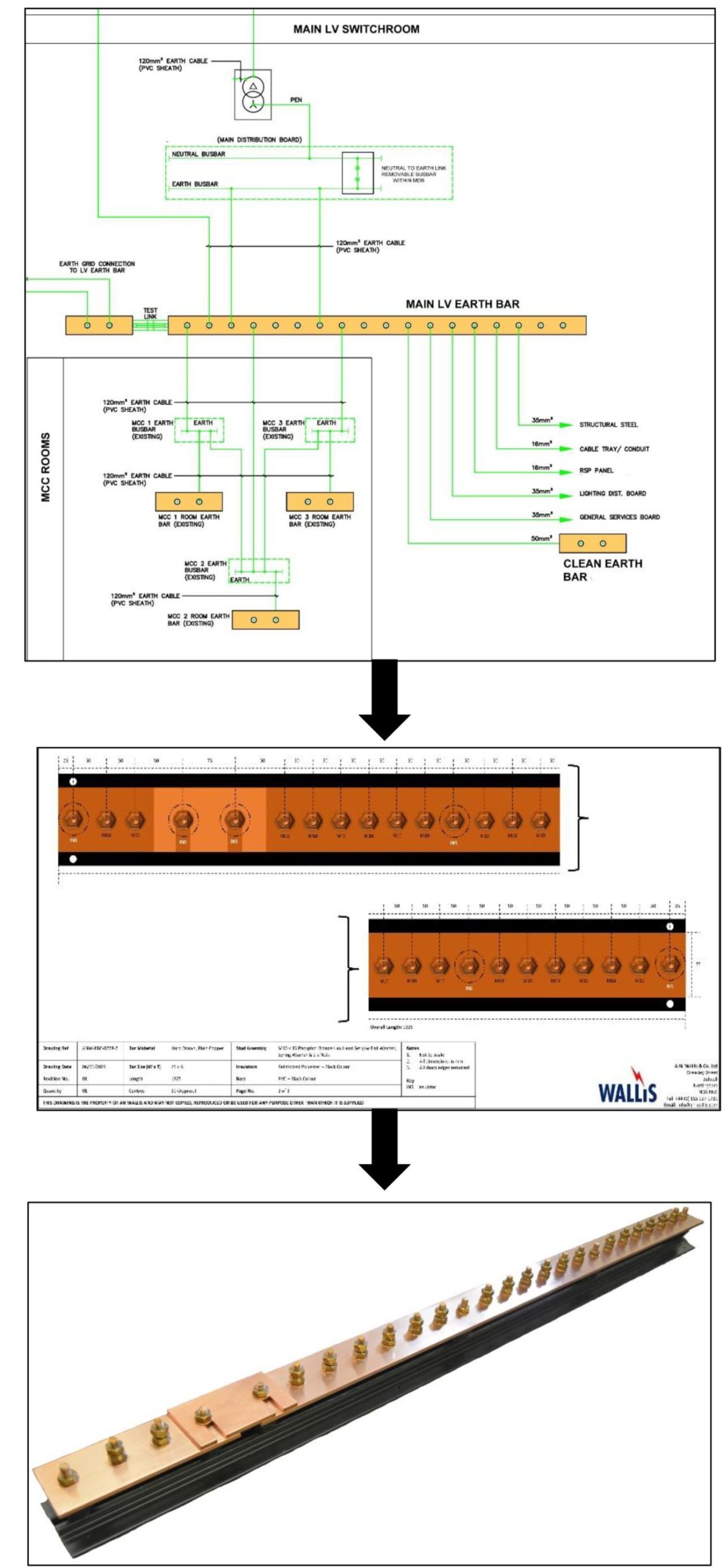
From Earthing Schematic to Earth Bar Drawing to Custom Manufactured Product.
Thorne & Derrick, UK Distributor for AN Wallis, can produce Earth Bar drawings directly from your Earthing schematic, this gives our customers a clear visual representation of the product that we can offer. This drawing can be approved (or amended) by the customer prior to us beginning the manufacturing process. This unique service ensures that the product quoted is the correct product and specification required by the customer avoiding any confusion or potential delays prior to manufacturing.
Thorne & Derrick distribute an extensive range of standard and customised special earth bars – here are the basic specification and selection factors:
- Type – Standard | Single | Twin | Multiple Links
- Termination Configuration – i.e. 1 Way + Link + 6 Way + Link + 3 Way
- Copper Bar Sizes – 50mm x 6mm Standard | or Custom Specification
- Copper Bar Finish – Bare (Standard) or Tinned Copper
- Cable Lug Termination Size – M6 | M8 | M10 Standard | M12 | Other
- Termination Material – Phosphor Bronze (Standard) | Brass | Stainless Steel
- Termination Spacings – 50mm Standard | Custom Specification
- Length Restrictions – Yes | No | Specify
- Base Material – PVC Standard | AVG Galvanised Steel | None
You can contact us with your enquiry.
Customised Earth Bars
➡ Some recent examples of custom manufactured products to client specifications.
| 6 Way + Link + 1 Way Tinned Copper Earth Bar, Stainless Steel Bolts, Mounted on Insulators & Black PVC Base. |  |
| 6 Way + Link + 1 Way Plain Copper Earth Bar, Brass Bolts, Mounted on Insulators & AVG Galv. Steel Base. | 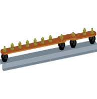 |
| 6 Way + Link Plain Copper Earth Bar, Phosphor Bronze Bolts, Mounted on Insulators & Black PVC Base. | 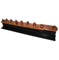 |
| 16 Way + Link + 2 Way Plain Copper Earth Bar, Brass Bolts, Mounted on Insulators & AVG Galv. Steel Base. |  |
| Telecommunications Earth Bar. | 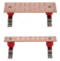 |
| 24 Way Special Earth Bar (2 Rows of 12 No. for Double Holed Lugs), 100x6mm Plain Copper Bar, M10 Brass Bolts, Mounted on Insulators & AVG Galv. Steel Base. | 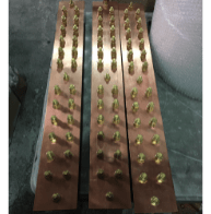 |
| 10 Hole Earth Bar, 50x6mm Plain Copper Bar, No Bolts, Mounted on Insulators & AVG Galv. Steel Base Feet. | 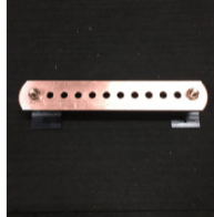 |
| 5 Way + Link + 3 Way Earth Bar, 50x6mm Plain Copper Bar, M10 Phosphor Bronze Bolts, Mounted on Insulators & Black PVC Base. | 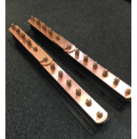 |
| 1 Way + Link + 1 Way Tinned Earth Bar, 50x6mm Tinned Copper Bar, M10 Brass Bolts, Mounted on Insulators & AVG Galv. Steel Base. | 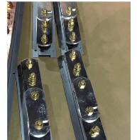 |

1. 20 Way Staggered Earth Bar, 50x6mm Plain Copper Bar, M6 Phosphor Bronze Bolts, Mounted on Insulators & Black PVC Base. 2. 16 Way Staggered Earth Bar, 50x6mm Plain Copper Bar, M6 Phosphor Bronze Bolts, Mounted on Insulators & Black PVC Base. 3. 10 Way Earth Bar, 50x6mm Plain Copper Bar, M6 Phosphor Bronze Bolts, Mounted on Insulators & Black PVC Base.

10 Way + Link + 1 Way Earth Bar, 25x3mm Plain Copper Bar, M10 Phosphor Bronze Bolts, Mounted on Insulators & Black PVC Base
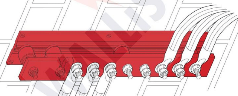
Copper Earth Bar Features
50mm Centres
- Standard 50mm hole centres will accommodate most earthing cable sizes
- Earth bar can be manufactured with different size hole centres
BS EN 62561-1 Class H
- Tested to BS EN 62561-1: Lightning Protection System Components (LPSC) – Part 1: Requirements for connection components
- Class H – Heavy Duty
Rounded Copper Edges
- Safer
- Easier to handle
- No sharp edges
PVC Base
- Entirely corrosion proof
- Lightweight earth bars
- High impact
- Can offer galvnised base as an alternative
PB Connection Points
- Phosphor bronze bolts, nuts, flat and spring washer
- Not Brass
- PB has better conductivity and better corrosion properties for corrosive atmospheres
BS 7430
- Designed and manufactured in accordance with BS7430 : Code of practice for protective earthing of electrical installations
AN Wallis
“I have worked with Thorne & Derrick throughout my 20 year career in the Earthing & Lightning Protection industry – we have worked closely together on multiple major UK and international projects.
“We are now working together again, using the historical AN Wallis brand and our high quality earthing products coupled with the incredible Thorne & Derrick customer service, sales and marketing abilities and their exceptional digital content to bring the focus to AN Wallis so that it is the only name thought of when requiring Earthing materials / Lightning Protection products”
- Jason Leatherland, AN Wallis Business Development Manager – Wholesale & Distribution

Earthing Bars | Standard, Single & Twin Links | Manufactured from Copper by AN Wallis
FURTHER READING
- Earth Tape – The Manufacture of Copper Earthing Tapes
- High Voltage Earthing & Grounding System Design Protecting Lives
- Copper Earthing Tape & Rods Protecting 33kV Substation & Transformer Bund
- Substation Earthing

Thorne & Derrick
Thorne & Derrick distribute the most extensive range of Low & High Voltage Cable Installation & Electrical Distribution Equipment to the Power Transmission & Distribution industry in the onshore and offshore wind, solar, rail, oil/gas, data centre, battery storage and utility sectors.
We service UK and international clients working on underground and subsea cables, overhead lines, substations and electrical construction at LV, 11kV/33kV up to EHV transmission and distribution voltages.
Key Products: MV-HV Cable Joints & Terminations, Cable Cleats, Duct Seals, Cable Transits, Underground Cable Protection, Copper Earth Tapes, Cable Jointing Tools, Feeder Pillars, Cable Ducting, Earthing & Lightning Protection, Electrical Safety, Cable Glands, Arc Flash Protection & Fusegear.
Distributors for: 3M Electrical, ABB, Alroc, Band-It, Cembre, Centriforce, CMP, Elastimold, Ellis Patents, Emtelle, Furse, Lucy Zodion, Nexans Euromold, Pfisterer, Polypipe, ProGARM, Prysmian, and Roxtec.
- Scope –single-source supply of extensive range of products
- Stock – a multi-million pound stock holding provides complete global supply solutions
- Staff – technical support from a trained, proactive and friendly team
- Delivery – UK stock turnaround with express logistics to all international destinations
Specialist Electrical Equipment Distributors for High Voltage Power Systems
Nexans Euromold 33kV Connectors Terminating XLPE 630sqmm Cable Onto Schneider CBGS (GIS) Switchboard
June 15th, 2021Images Courtesy of: Stuart Henry – Director/Cable Jointer LV-66KV, 11KV Electrical Fitter at Kyadan Ltd
Pictured: Nexans Euromold 33kV Connectors Terminating XLPE Single Core 630sqmm Cable Onto Schneider CBGS (GIS) Switchboard
Thorne & Derrick are Main Distributors for the complete range of Nexans Euromold MV Cable Connectors, Cable Joints and Terminations for connecting medium voltage cables to gas insulated switchboard (11kV-33kV) – this includes Nexans Cable Jointing Tools.
1. Once medium voltage testing is completed the earth screens will be finished off.
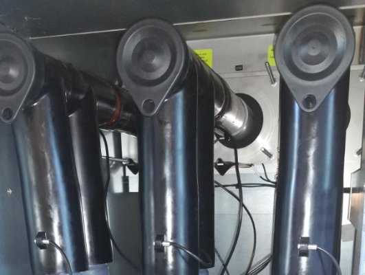
2. Nexans Terminations on Schneider CBGS with VT Leads completed with Steve Roberts
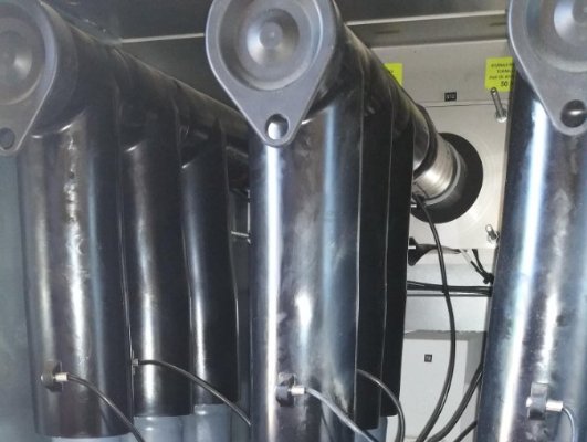

Jointers blog
Subscribe now to our POWER NEWSLETTER– a monthly email circulation packed with news, projects, videos, technical tips, training information, promotions, webinars, career opportunities and white papers.
Includes access to our popular JOINTERS BLOG with contributions from utility professionals, linesmen and cable jointers working on MV HV EHV cables and overhead lines typically at 11kV, 33kV, 66kV and up to 132kV.
15,000+ Subscribers. ➡ 
Laser Scanning 132kV High Voltage Substations Using Topcon GLS-2000 Scanner
June 15th, 2021
Compact Lightweight Multi-adjustable Laser Scanner
“The Topcon GLS-2000 series laser scanner we used within the 132kV substation was the Topcon GLS-2000M – the GLS-200 series is composed of 3 comparable, yet distinct models: the GLS-2000S (short-range), GLS-2000M (middle-range), and the GLS-2000L (long-range),” explains Richard Shepherd, MD at Utility & Transmission Survey Solutions Ltd.
Topcon laser scanner is a full featured scanner that can be effectively used to capture existing, as-built conditions for any application range. The compact, lightweight series of scanners accurately captures a full 360° scan including images in less than three minutes.
- Selectable laser modes Class 3R to Class 1M
- Multiple lens array system – quickly switches focal length settings
- Auto temperature adjustment – consistent accuracy throughout the work day
- Precision – signal processing wave form for the ultimate in precise data
132kV Substation Scanned Using Topcon GLS-2000M Laser Scanner

PR : Topcon Positioning Group announces the release of three new models to the GLS line of laser scanners — the GLS-2000S, GLS-2000M and the GLS-2000L.
The scanners are designed to capture data based on the measurement range needs of specific applications.
“These new GLS-2000 scanners offer purposeful solutions and versatility that comes from the multiple measurement modes with each model,” said Charles Rihner, Vice President for the Topcon GeoPositioning Solutions Group. “The S model is optimized for short-range applications, while the M and L models are perfect for medium and long-range measurement fields, respectively.”
Using Topcon Precise Scan Technology II, the GLS-2000 models are designed to emit pulse signals three times faster than earlier GLS systems. “Using faster pulse signals enables timing to be detected more precisely, which results in reduced noise and higher-accuracy data,” said Rihner.
Additionally, the systems feature dual 5MP cameras, including one with a 170-degree wide-angle lens for high-speed imaging, as well as an 8.9-degree telephoto camera that is coaxial with the measuring axis.
When paired with Topcon ScanMaster software, the models provide complete systems for capturing and processing 3D point cloud data.
Topcon Laser Scanners For Substation, Transmission & Power Utility Scanning

Thorne & Derrick Specialist Electrical Distributor
Established since 1985, T&D distribute the most extensive range of LV, MV & HV Cable Jointing, Terminating, Pulling & Installation Equipment – contact us today for a competitive quotation.
Key Products : MV Joints & Terminations, Cable Cleats, Duct Seals, Cable Transits, Underground Cable Protection, Jointing Tools, Feeder Pillars, Cable Duct, Earthing & Lightning Protection, Electrical Safety, Cable Glands, Arc Flash Protection & Fusegear.
Distributors for : 3M, Pfisterer, Nexans Euromold, Elastimold, Catu, Roxtec, Emtelle, Centriforce, Lucy Zodion, Alroc, Hivotec, Cembre, Prysmian, Ellis Patents, ABB & Furse.
Jointers blog
Subscribe now to our POWER NEWSLETTER– a monthly email circulation packed with news, projects, videos, technical tips, training information, promotions, webinars, career opportunities and white papers.
Includes access to our popular JOINTERS BLOG with contributions from utility professionals, linesmen and cable jointers working on MV HV EHV cables and overhead lines typically at 11kV, 33kV, 66kV and up to 132kV.
15,000+ Subscribers. ➡
Intercable Tools | Stripping MV Cable XLPE Insulation Using Intercable Jointing Tools
June 15th, 2021Images Courtesy of: Beau Smithers – HV Cable Jointer at S.I Cable Jointing Services
Modern-day cable jointers utilise a broad range of Cable Jointing Tools to ensure precision accuracy and clean removal of cable sheath, cable insulation, semi-conductive screens and core preparation. This picture shows the cable jointer using Intercable cable stripping tools to remove the XLPE insulation from medium voltage power cables to enable application of the cable termination.

Every millimetre is critical in the medium voltage cable preparation process where primary insulation diameters must be carefully measured to prevent possible future cable failures. 
Quick strip to check outer diameters layer by layer prior to installing cable terminations.
intercable
INTERCABLE stands for high quality products and service.

Intercable is an efficient organisation, with quality management standards set according to the EN ISO 9001 international standards to guarantee optimum processes and continual improvement.
They have set themselves a clear goal: to provide workers in the electrical technology sector with the very best tools and equipment for performing their daily tasks.
Intercable’s own innovation department with highly qualified experts and the latest technology in the planning and construction sector, along with in-house design and production in Italy and Germany, guarantees success and continuous improvement.
Jointers blog
Subscribe now to our POWER NEWSLETTER– a monthly email circulation packed with news, projects, videos, technical tips, training information, promotions, webinars, career opportunities and white papers.
Includes access to our popular JOINTERS BLOG with contributions from utility professionals, linesmen and cable jointers working on MV HV EHV cables and overhead lines typically at 11kV, 33kV, 66kV and up to 132kV.
15,000+ Subscribers. ➡


