Blog
Partial Discharge Secrets, Tips & Tricks by William Higinbotham (President) at EA Technology
June 7th, 2021Partial Discharge
-
Special Thanks To William Higinbotham President at EA Technology for allowing T&D to republish
Most of us started our electrical careers with fairly good knowledge about the practical aspects of our jobs. We understood voltage, current, power, resistance, etc.
We mastered the more esoteric areas such as electrical fields and electrical stress control and only revisited these topics if our day-to-day job required it. Partial discharge (PD) is one of those areas where we might have learned how to identify it or how to use a test set, but most of our roles have not exposed us to the ins and outs of this topic.
In this article, I share some unexpected things I have learned while working with clients on partial discharge issues. I hope this includes the secrets, tips, and tricks you always wanted to know about partial discharge but were afraid to ask.
Can Cable Termination Mistakes Cause PD?
When a termination containing multiple layers and different materials is exposed to an electric field, the voltage stresses are larger in the areas of lesser permittivity.
Air has a permittivity about 2.3 times lower than insulation, so a void in the termination will have approximately 2.3-times-higher field stresses. Combined with a 10-times lower dielectric strength, this leads to discharge across the void.
Cable terminations are specifically engineered to ensure voltage stresses do not exceed the insulation capability at any point. This is accomplished by ensuring the voltage gradients across the insulation are even (Figure 1).
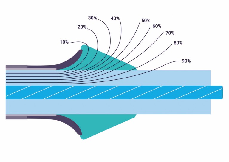
FIGURE 1 VOLTAGE GRADIENTS IN A CABLE TERMINATION
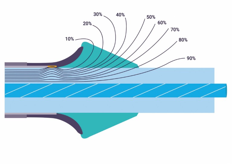
FIGURE 2 VOLTAGE GRADIENTS IN A POOR TERMINATION
Voids can be caused by common mistakes in terminations. Failure to completely fill gaps between insulation and conductors with mastic is very common. Imprecise trimming of semiconductor layers can leave a void where the stress tube cannot fill the poorly trimmed section. Failing to fully clear the semiconductor layer off the insulation causes a concentration of stress and results in PD even if there is no void. Figure 2 shows that electrical stress is greater in and around the void.
Cable termination procedures are precisely engineered, and any failure to follow them closely can lead to voids, field concentration, and partial discharge. An example of this can be seen in Figure 3, where an overly large gap that was not filled with mastic led to failure.
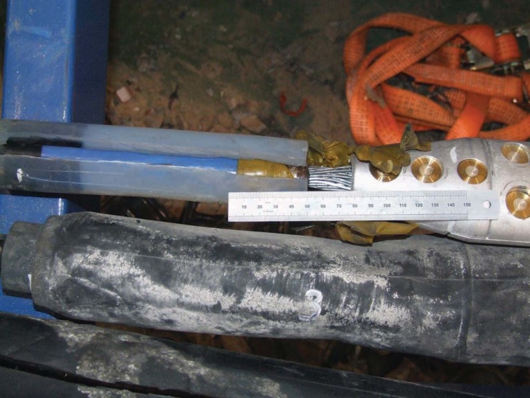
FIGURE 3 DEFECTIVE CABLE TERMINATION
Can Incorrect RFCT Placement Induce PD?
When performing an online partial discharge test on a cable, a radio frequency current transformer (RFCT) must be attached to the cable ground strap. In placing the RFCT, think 95% about safety and 5% about getting a good signal. Improper placement of an RFCT can affect both safety and signal.
For safety reasons, ensure you have a solid ground capable of withstanding any phase-to-shield fault current. Also ensure the RFCT is away from the termination and close to the ground bar so the RFCT is still safe if the ground does separate. Figure 4 shows an RFCT placed on an adequate ground close to the main ground bar and away from the termination.
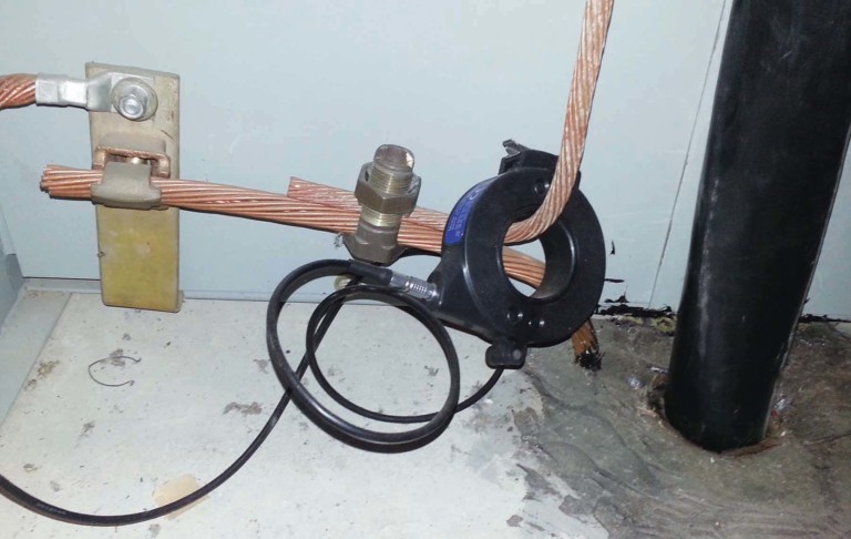
FIGURE 4 PROPERLY PLACED RFCT
Is that the only reason you put the RFCT away from the termination? Remember that the termination is where the electric field goes from nice and contained inside the shield to free and unrestrained after the shield cut-back. The termination is designed to allow the field to spread out gradually so there is a lesser field but evenly distributed around the termination.
The closer you get to the termination, the stronger the field becomes. Allowing the RFCT inside that field can induce PD. It probably will not lead to failure unless it is very close, but it will make it impossible for that RFCT to discern any real PD.
What Are Contact Discharge and Floating Metal Discharge?
Contact discharge is caused by a poor high-voltage connection where sparks can jump across the gap at set times on the sine wave when the voltage level is high enough. These defects usually produce heat as well as ultrasonic sound that can be detected.
A related discharge — floating metal discharge — is an electrical discharge that takes place due to floating metal in the electric field. The floating metal typically acquires an electric charge from the field and then discharges to ground, the conductor, or via corona through the air. Common examples include tools or hardware left in a cabinet after work is performed.
Contact discharge and floating metal discharge have characteristic phase resolved partial discharge (PRPD) plots where the level of discharge is consistent as the voltage increases (Figure 5). These two types of discharge emit similar patterns, so it can be difficult to differentiate between the two.
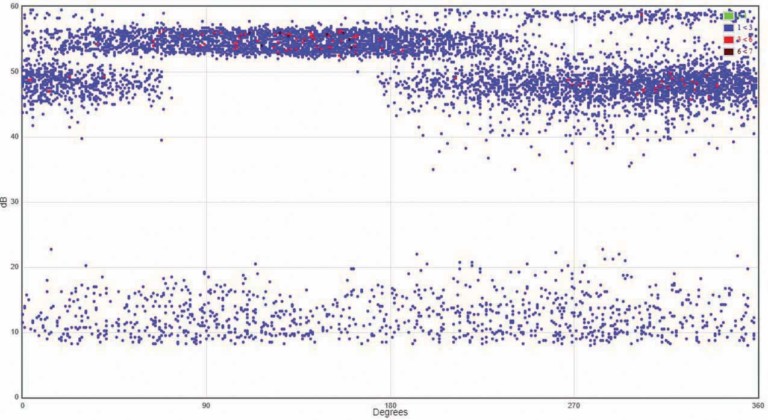
FIGURE 5 PHASE RESOLVED PARTIAL DISCHARGE PLOT
The phase resolved pattern indicates that PD magnitude does not change despite the change in voltage. This is because the distance from the gap at the poor HV connection or the floating metal to the live conductor is constant; therefore, the flashover voltage remains the same.
The discharge phase angle actually moves with each succeeding discharge due to the physics of this type of discharge. The variance in phase and consistency in discharge amplitude produces these characteristic flat, broad lines in the PRPD. This characteristic can be used to identify this type of discharge and make it easier to find the offending component.
Contact discharge can cause failure due to the poor HV connection, whereas floating metal discharge tends not to lead to catastrophic failure. Both discharge types create a strong signal that often masks more damaging types of discharge. Ensure you eliminate this so you can see other discharge sources.
Is It Better to Ground the Cable
at One End or Both?
When you design a cable system, you have an option of grounding the shield at one end or both ends. If one end is ungrounded, a sheath voltage limiter (SVL) is typically placed on that end. The shield of a cable capacitively and inductively couples to the conductor, thereby acquiring potentially dangerous voltage.
If both ends are grounded, the sheath voltage will be lower than if one end is an open circuit, especially during a fault. The downside of grounding both ends is that circulating currents can heat the cable and reduce its ampacity.
If a cable grounded at one end shows PD, the current has nowhere to go except the ground strap where the RFCT is located. This allows you to measure the total PD current. If the cable is grounded at both ends, the PD current will divide according to the ratio of impedances in either direction. This gives a lower reading.
However, there is a bright side: Testing both ends of the cable allows better sensitivity overall. A small discharge on one end might not be detectable at the other end.
Is There a Standard for Acceptable
PD Levels in Cables?
The world of electrical testing is largely predicated on the fact that we can assign a threshold. Above the threshold is considered bad, and below the threshold is considered good, or vice versa.
As an example of the latter, in an insulation resistance test at 1kV, above 100 Megaohms is generally considered good for many equipment types while below 100 Megaohms is suspect or bad. These test methods and thresholds are codified in international, peer reviewed, and balloted standards to ensure they are accurate.
The world of partial discharge testing has very few approved standards, and most of them contain vague words like “should” and “may” instead of “shall” and “must.” Cable PD testing is especially void of standards that include hard and fast thresholds. ANSI/NETA MTS 2019 is the first United States standard to include online PD testing, but it doesn’t cover cables. IEEE 400.3 is specifically for field PD testing of cables, but it has no thresholds.
This lack of standardized acceptance levels can be traced back to the very nature of PD. It is an unfortunate fact that the absolute PD level is not directly relatable to the likelihood of failure or the time to failure. PD levels go up and down with a variety of influencing factors: Voltage, current, ambient temperature, relative humidity, time since inception, defect carbonization, and other factors.
With all these variables unrelated to the test method, it is difficult to arrive at threshold levels. Trending over time or comparison to similar assets remains the best way to gauge the severity of PD. You may not be able to predict when something will fail, but you can identify bad actors for further study.
Which Is Better — Online or Offline PD Testing?
This is a bit of a trick question. The tests are quite different, and they tell us different things. Both have their place in any maintenance and reliability program. It is important to understand their different strengths.
Online PD Testing is usually the first step. You can test all your assets quickly and efficiently to see what is good and what needs further study. You are testing under real-world conditions of voltage, current, frequency, and load. If PD does not exist in the real-world conditions, there is no need to be too concerned.
You can test all your assets without taking anything out of service or opening any panels to do the tests.
Typically, a very small percentage of assets record any PD. The downside is that online PD testing will tell you less about PD than an offline test.
Offline PD Testing is as close as you can get to factory testing in the field. You can vary voltage and see noise-free PD patterns. You can see exactly at what voltage PD begins and ceases.
Unfortunately, it’s not all good news. You must take the equipment out of service and bring in large, heavy, expensive test equipment. You are also not working in a real-world condition, so results may not be fully representative of normal conditions.
An offline test takes 10 to 20 times longer than an online test. The frequency is typically not power system frequency, and there is no load current, so the temperature profile is also different.
The global best practice is to do online testing or monitoring on all assets and do offline tests on the small population of assets that give indications of PD online.
Can You Find PD Inside Switchgear by Testing the Cable?
Transient earth voltage (TEV) is a standard technique for finding partial discharge inside medium-voltage metal-clad switchgear. The TEV effect, discovered in the late 1970s by Dr. John Reeves of EA Technology, has become the basis for non-invasive testing for internal discharge.
Voltage is induced on the outside surface of metal-clad gear as a result of discharge inside the gear. This voltage is a narrow pulse of a few microseconds and amplitude in millivolts. Measuring TEV can be very difficult because the signals of interest are hidden in noise.
One trick we have learned is that performing a TEV test on the outside of a cable exiting the cubicle is an excellent way to find PD inside the cubicle. A TEV probe on the outside of the sheath will couple to the shield and often provide a higher signal than the outside of the switchgear.
The PD pulse in the switchgear will travel down the conductor and radiate to the shield. However, gaining access to the cables within a meter of the switchgear is not always possible. With IEC-type gear, the cables are exposed. In most cases with ANSI gear, you will need access below the cabinet. Many industrial substations are raised or have a basement that allows access. If at all possible, try it out.
How Soon After Energizing Can You See PD?
Traditional knowledge held that partial discharge took years or decades to develop. The standard response was “all my equipment is new! I don’t need to do PD testing.”
In some instances, PD takes a long time to start. The thermal cycling that occurs throughout device operation can cause voids over time, and internal discharge can take decades to cause failure. However, as we have learned recently, early-life PD and failures are quite common.
The oil sands region of Alberta, Canada, has seen explosive growth in the past 25 years, and the demand for jointers outstripped the qualified supply. Cable failures within the first 12 to 18 months were common. Data centers and windfarms have similarly driven cable installation rates to rise, and early failure rates in those applications are well above acceptable levels.
If the conditions are right for PD, there is no physical reason for it not to start immediately. It may be so low as to be undetectable at first, but it can be present. PD is more likely to be caused by workmanship than by aging, and bad workmanship is there from day one.
In Figure 6, a monitoring system was installed on a cable with new splices; PD was detectable by day 10. By day 14, it was 300 pC — not quite ready to fail, but clearly a rapid increase immediately after energizing.
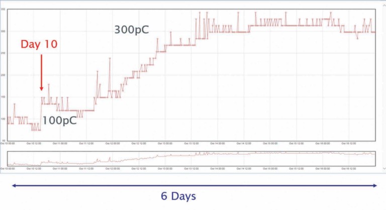
FIGURE 6 PARTIAL DISCHARGE OVER TIME
Figure 7 is an EHV termination that failed within days of energization. PD would have been detectable immediately.
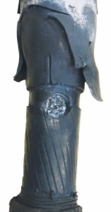
FIGURE 7 FAILED EHV TERMINATION
Conclusion
I hope these few examples have been interesting and enlightening. While partial discharge is still a developing topic in our industry and we continue to find new things every day, the information we can learn about our assets is worth the learning curve.

William G. Higinbotham has been president of EA Technology LLC since 2013. His responsibilities involve general management of the company, including EA Technology activities in North and South America. William is also responsible for sales, service, support, and training on partial discharge instruments and condition-based asset management. He is the author or co-author of several industry papers.


Thorne & Derrick distribute the most extensive range of Low & High Voltage Cable Installation & Electrical Distribution Equipment to the Power Transmission & Distribution industry in the onshore and offshore wind, solar, rail, oil/gas, data centre, battery storage and utility sectors.
We service UK and international clients working on underground cables, overhead lines, substations and electrical construction at LV, 11kV/33kV and up to and EHV transmission and distribution voltages.
Key Products: MV-HV Cable Joints & Terminations, Cable Cleats, Duct Seals, Cable Transits, Underground Cable Protection, Copper Earth Tapes, Cable Jointing Tools, Feeder Pillars, Cable Ducting, Earthing & Lightning Protection, Electrical Safety, Cable Glands, Arc Flash Protection & Fusegear.
Distributors for: 3M Electrical, ABB, Alroc, Band-It, Cembre, Centriforce, CMP, Elastimold, Ellis Patents, Emtelle, Furse, Lucy Zodion, Nexans Euromold, Pfisterer, Polypipe, ProGARM, Prysmian, and Roxtec.
- Scope –single-source supply of extensive range of products
- Stock – a multi-million pound stock holding provides complete global supply solutions
- Staff – technical support from a trained, proactive and friendly team
- Delivery – UK stock turnaround with express logistics to all international destinations

Masterclass : Pirelli 33kV Fluid Filled Oil Cable Jointing
May 26th, 2021uploaded by Chris Dodds – Sales Marketing Manager at Thore & Derrick
All Images Courtesy : Andrew Brezovszky (EHV Cable Jointer).
In a previous Guest Blog Andrew taught us the theoretical formula and then demonstrated the practical skill required in calculating and installing premoulded sleeves when jointing 110kV Extra High Voltage cable.
Today, Andrew leaves the classroom for the cable trench and provides a new Masterclass in “old-skool” oil cable jointing.
This contrasts perfectly with his modern day classic, XLPE Masterclass : 110kV Cable Preparation & Termination Using Prysmian Outdoor Sealing Ends
The 2 Masterclasses demonstrate the true depth of experience and craftmanship accumulated over decades that world class cable jointers hold – the ability to joint all cable types, whether oil, paper or XLPE with professional Certification across all manufacturers whether Pfisterer, ABB, Tyco, Brugg, 3M or Taihan.
Due to the polymeric dominance of modern cable manufacturing many of the “traditional” jointing skills are no-longer taught in the jointing schools. This is reinforced by cable accessory manufacturers making technological revolutions in the design of cable joints and terminations, such as 3M QS4 Cold Shrink.
Increasingly at 11kV and 33kV voltages cable joints and terminations are now designed to simplify the installation process – while this is not a deliberate attempt to “de-skill” cable jointing it inevitably leads to a slimmer skill-set requirement for todays MV jointer.
This series of Photographs is an enthralling counterpoint to the daily stream of “polymeric posts” on our Blog.
Pictured : 33kV Fluid Filled 3 Core Cable, 0.5 Square In.(cca 325sqmm) Copper Conductor PAPVC (Aluminium Sheathed). Made by Pirelli Cables. Pirelli transferred ownership to Goldman Sachs Capital Partners and is now called Prysmian Cables & Systems Limited.
Pictures show the process of cable excavation, preparation and jointing. The sequence also shows site set-up with 2 separate scaffolding for the cable joint bays, fencing, generator, lighting tower, oil trailer, shipping container for jointing tools and materials.
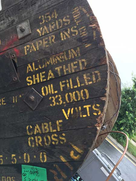
Pictured : In 2014, Prysmian (formerly Pirelli Cables) celebrated 100 years in Southampton UK. Cable Braiding Machine and Lowering Paper Cables Into A Vacuum.


New 33kV cable supported by cable rollers and jacks pulled in from drum and installed
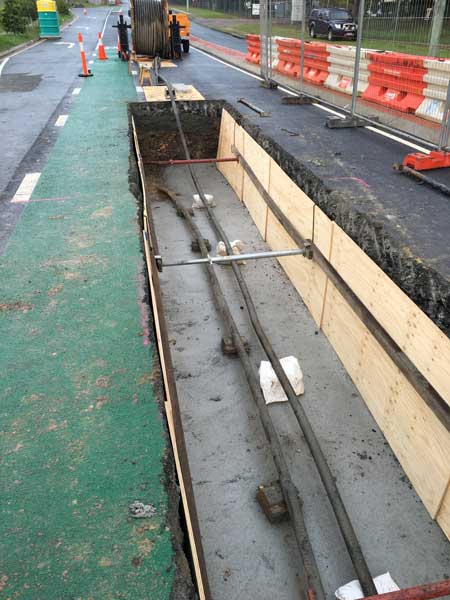
Platforms Erected – 33kV cable ready for cut and cap
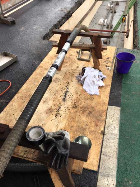
Cable Cut & Cap Plumbed Onto Drum – oil lines reconnected after final flush
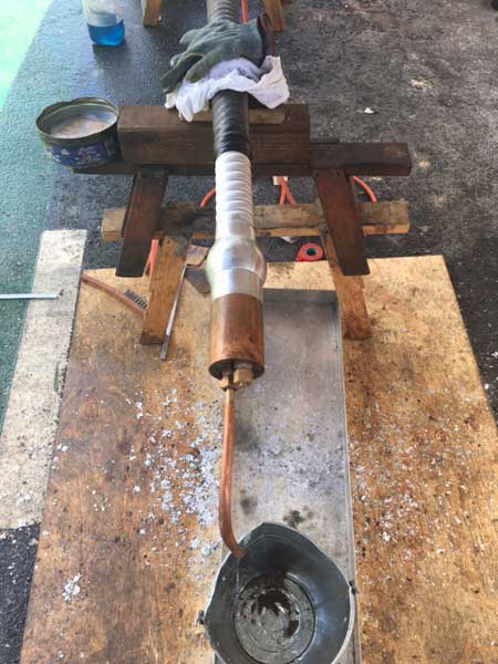
Flow Board & Oil Trailer – the supply is set and ready for cutting the cable the next morning
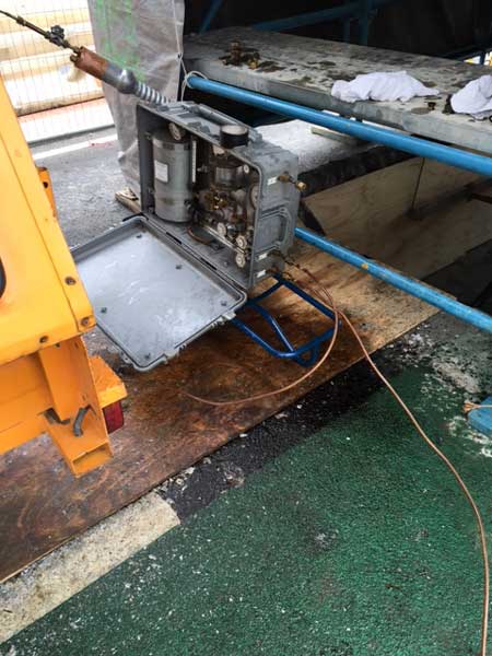
Cables Cut, Flushed From Filing & Impurities – the 33kV aluminium cable sheath is removed with great care so the cores and insulation are not damaged. The cable gland is then plumbed onto the cable sheath.
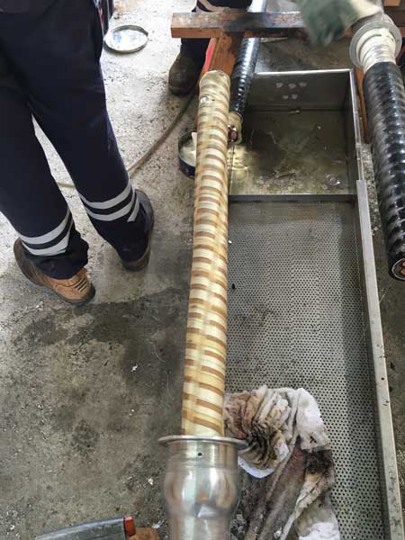
33kV Cable Preparation- after more cable preparation work the 33kV cable cores are set, measured and cut to length
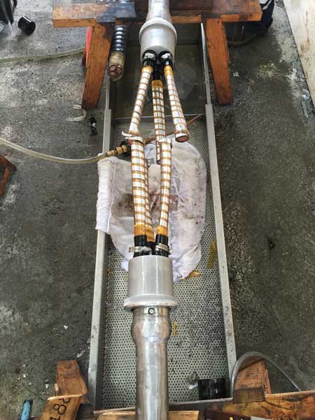
Sorry – doing the sweating left me with no hands, so that’s the final product
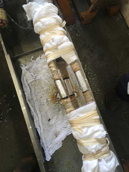
Ferruling – 33kV cable ferrules cleaned up
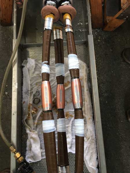
Chamfered 33kV Cores Ready For Taping – the white tape isn’t insulation tape 😉 just saying!
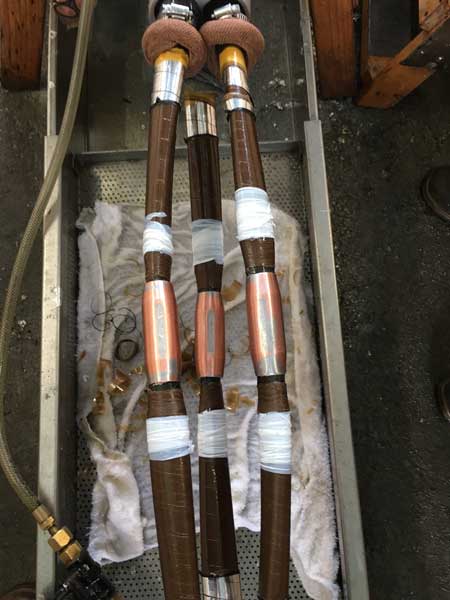 Cores Taped
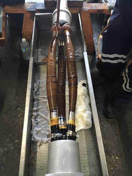
Installing Screening Layer
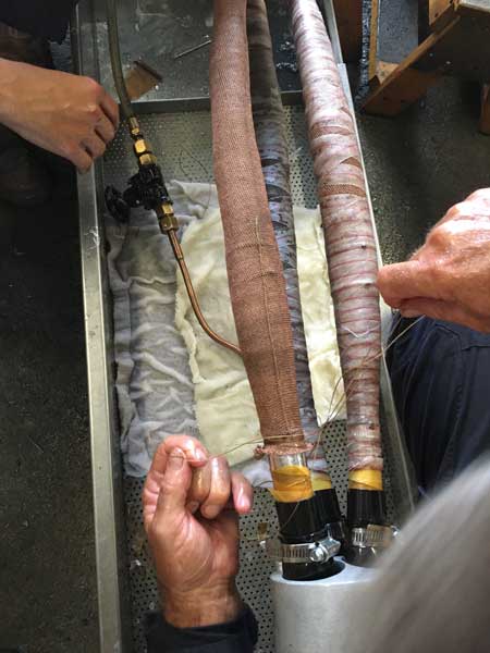
Padding
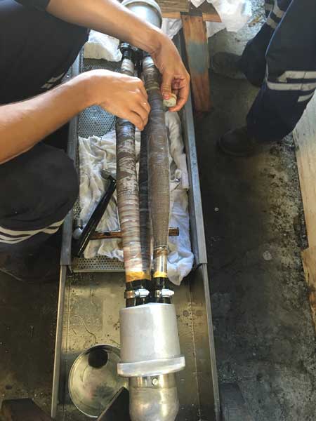
33kV Can Installed
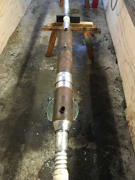
33kV Outer Joint Box Installed
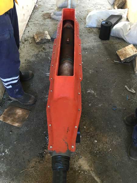
Pirelli – all jointing materials, cable, taping paper supplied by Pirelli
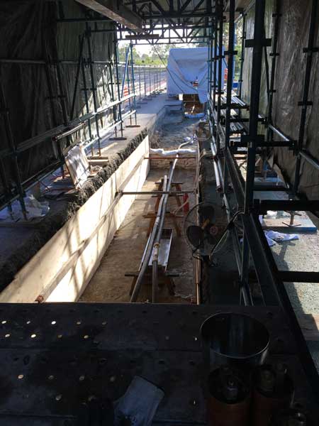


Jointers blog
Subscribe now to our POWER NEWSLETTER– a monthly email circulation packed with news, projects, videos, technical tips, training information, promotions, webinars, career opportunities and white papers.
Includes access to our popular JOINTERS BLOG with contributions from utility professionals, linesmen and cable jointers working on MV HV EHV cables and overhead lines typically at 11kV, 33kV, 66kV and up to 132kV.
15,000+ Subscribers. ➡ 
132kV Substation Cable Joints (Taihan) – XLPE Single Core 1200sqmm
May 26th, 2021Image Courtesy of: Joseph Deapera – Technical & Commercial Director at Power Projects Contracting
Pictured: 132kV Substation Cable Joints (Taihan) – XLPE Single Core 1200sqmm

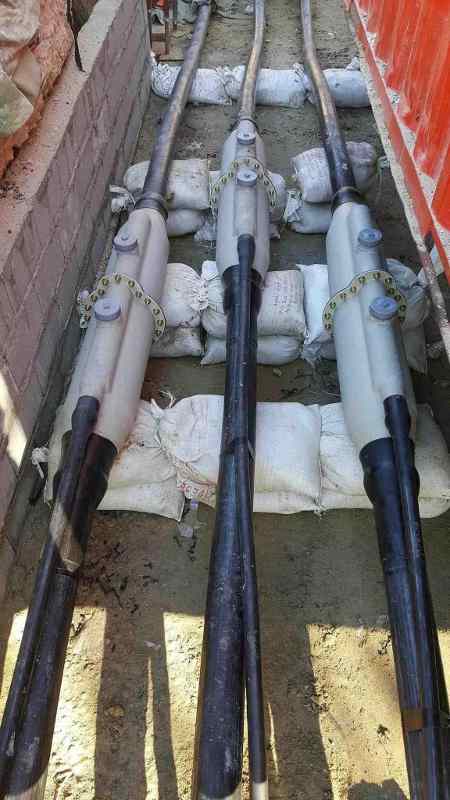
Thorne & Derrick Specialist Electrical Distributor
Established since 1985, T&D distribute the most extensive range of LV, MV & HV Cable Jointing, Terminating, Cable Pulling & Installation Equipment – contact us today for a competitive quotation.
Key Products : MV Joints & Terminations, Cable Cleats, Duct Seals, Cable Transits, Underground Cable Protection, Jointing Tools, Feeder Pillars, Cable Duct, Earthing & Lightning Protection, Electrical Safety, Cable Glands, Arc Flash Protection & Fusegear.
Distributors for : 3M, Pfisterer, Nexans Euromold, Elastimold, Catu, Roxtec, Emtelle, Centriforce, Lucy Zodion, Alroc, Hivotec, Cembre, Prysmian, Ellis Patents, ABB & Furse.
Jointers blog
Subscribe now to our POWER NEWSLETTER– a monthly email circulation packed with news, projects, videos, technical tips, training information, promotions, webinars, career opportunities and white papers.
Includes access to our popular JOINTERS BLOG with contributions from utility professionals, linesmen and cable jointers working on MV HV EHV cables and overhead lines typically at 11kV, 33kV, 66kV and up to 132kV.
15,000+ Subscribers. ➡
Pfisterer Connex 6S Inner Cone Plugs Terminating 300kV Nexans Cables Into GIS
May 26th, 2021- Cable : Nexans USA (XLPE 300kV)
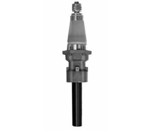
- Cable Termination : Pfisterer Connex
- Cable Jointer : Andy O’Malley (Allteck Power Line Contractors)
Nexans 300kV cable (220kV circuit voltage) is shown prepared for termination using (245kV). The HV circuit is terminated into GIS (Gas Insulated Switchgear) using Pfisterer Connex.
Pfisterer Connex medium and high voltage cable plug termination system is specified on global power projects for use in high load ring main units, circuit breaker switchgear, high voltage motors, transformers, capacitors, transducers and cable joint boxes.
 T&D are Main Distributors & Stockists for the Pfisterer Medium Voltage Power Products including Connex Plugs, Cable Jointing Tools, Sicon Connectors, Surge Arresters and Electrical Safety Equipment.
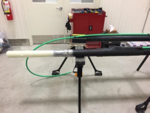
Image : Goodbye Glass
Alroc AMF5 55-160 tool removes the need for HV jointers to “glass” the outer conductive sheaths as the highly precision engineered cable jointing tool provides accurate stripping of HV and EHV cables in a motor controlled rather than manual process.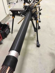
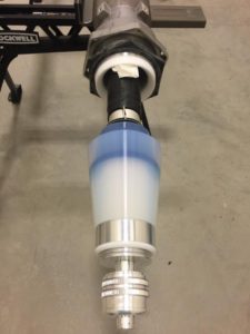
Safety Rules OK!
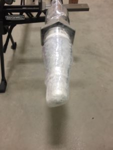
Pfisterer Connex 6S ready to plug in – the cable termination end is carefully protected and covered. This cable is situated inside a temperature controlled room and is “red-taped” to prevent unplanned entry.
“Great Safety is Great Business”
High voltage is high risk therefore worker safety is paramount at Allteck. Actually, it’s more than that – it is their number 1 core value.
According to OSHA, typical occupational hazards include :
- High voltage cable or power line contact
- Working at dangerous height
- Working in confined spaces
- Challenging weather conditions and terrain – urban and rural work locations
- Vehicle traffic
Correct PPE and fall arrest equipment are minimum safety requirements for the Lineman’s body. Most important is the “safety mindset” of the company – Allteck have a proud and proven track record in implementing the highest levels of safety standards.
Safety is at the heart of their company culture and reputation.

Jointers blog
Subscribe now to our POWER NEWSLETTER– a monthly email circulation packed with news, projects, videos, technical tips, training information, promotions, webinars, career opportunities and white papers.
Includes access to our popular JOINTERS BLOG with contributions from utility professionals, linesmen and cable jointers working on MV HV EHV cables and overhead lines typically at 11kV, 33kV, 66kV and up to 132kV.
15,000+ Subscribers. ➡
Arc Flash – The Definitive Guide to Protecting Lives
May 25th, 2021
Arc Flash Clothing
ProGARM are a market-leading Arc Flash Clothing, Garment & PPE manufacturer, delivering the ultimate in arc flash protective clothing and worker protection without compromising on wearer comfort.
Specialist Distributor & Customer Service
Thorne and Derrick are Approved Specialist Suppliers & Distributors of ProGARM Arc Flash Clothing & PPE providing competitive prices from extensive stocks with excellent customer service levels. We protect LV HV Cable Jointers, SAP’s, Overhead Linesmen, Substation & Electrical Engineers; whether racking and switching Medium Voltage switchgear or fusing Low Voltage feeder pillars – we have the correct clothing and workwear to provide safe protection against all calculated levels of arc flash hazards.
The dangers of Arc Flash incidents and protecting your workers with specialist Arc Flash & Flame Resistant Clothing has never been as front-of-mind as it is today and ProGARM supported by Thorne & Derrick have created the Ultimate Guide to Arc Flash which you can download your copy below.

Arc Flash Clothing | Polo Shirts | Coveralls | Helmets | Insulating Gloves
Contents of Arc Flash Guide
- What is Arc Flash
- Arc Flash Incident Reporting
- Risks & Consequences of Arc Flash
- Sectors Where Arc Flash is a Risk
- Arc Flash Test Methods
- Testing for Quality Assurance
- Testing for Quality Assurance
- Advising on Fabric
- Advising on Layers
- Questions to Ask your Customers
- Questions to Ask your Customers
- Glossary
- Resources
>> Download Your Guide To Here <<

💡 Did you know? – While high voltage equipment does increase the likelihood and intensity of arc flash explosions, they can occur in any live electrical environment – even low voltage.
Overview of Arc Flash Clothing | Contact us to discuss your garment and PPE requirements, we can mitigate risk with guidance on safe working practices and by providing appropriate worker clothing that offers advanced Arc Flash Protection that saves lives every day. Whether working on underground cables or overhead lines, here is a selection of workwear clothing – contact us to discuss your requirements;