

Blog
How To Repair Damaged Cables Using Wraparound Cable Repair Kits
May 20th, 2025
Installing Filoform cable repair kits
Integrity of the cable is of prime concern in mission-critical infrastructure.
Whether maintenance is being performed in utilities, telecommunications, or industrial power systems, damaged jacket cables significantly degrade operations and safety. Filoform Heat Shrinkable Reinforced Wrap Around Cable Jacket Repair Sleeves offer a tough, field-proven repair solution for on-site repair of cables, offering durability, environmental sealing, and mechanical protection.
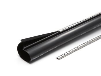
Filoform Jacket Repair Sleeve
The Filoform cable repair sleeve is engineered for reliability in hostile environments. This metal-reinforced, heat-shrinkable wraparound sleeve enables fast, permanent cable jacket repair without cable movement or disconnection.
Cable Repair Product Features
- Heat-activated seal with hot melt adhesive
- Metal channel closure for mechanical reinforcement
- Extensive cable diameter compatibility
- Application for indoor and outdoor use when repairing damaged cables
Cable Repair Installation Guide
Important: Use a soft yellow flame (not pencil type). Always direct heat in the direction of shrinking and maintain a sweeping motion to avoid scorching. Begin shrinking from the centre outward. Ensure uniform shrinking and proper adhesive oozing.
Ensure performance perfection with this precise installation procedure:
Step 1: 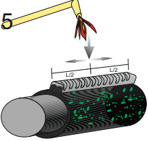
Action: Degrease, clean, and dust the cable surface where the sleeve will be applied.
✅ Use solvents that are compatible with the cable material.
✅ Clean 100 mm on both sides of the damaged section.
Step 2: 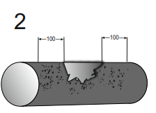
Action: Abrade the outer jacket of the cable using abrasive tape or sandpaper.
✅ Roughen 100 mm on each side of the damage for optimal adhesion.
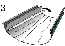 Step 3: Remove the Adhesive Film
Action: Peel off the release liner from the adhesive-coated inner surface of the sleeve.
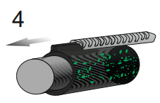 Step 4: Apply the Sleeve and Insert the Metal Channel
Action: Wrap the sleeve around the cable and slide the metal channel along the overlap to lock it.
✅ Extend the channel 10 mm beyond both ends of the sleeve.
✅ Confirm that the sleeve fits snugly around the cable.
Step 5: Start Heat Shrinking at the Center
Action: Begin applying heat at the centre of the sleeve and work outward.
✅ Apply uniform heat all around the sleeve.
✅ Focus extra heat along the metal channel.
✅ If necessary, bend the channel to follow the cable’s contours.
Step 6 Monitor Adhesive Flow
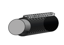
Action: Look for hot melt adhesive uniformly oozing from all edges.
✅ This indicates a secure and sealed installation.
✅ Let the sleeve cool fully before applying any mechanical stress.
Correct Installation of Hawke Cable Glands
May 16th, 2025
Thorne & Derrick | Distributed from Stock | Approved Supplier | UK & Export Sales
Hawke Cable Glands Installation
Installing Hawke cable glands correctly is essential to ensure the integrity, safety, and performance and cable termination of your LV MV HV electrical systems—especially in hazardous environments like oil & gas, petrochemical and industrial sectors.
In this guide, we’ll walk you through the correct method for installing Hawke cable glands, share common mistakes to avoid, and explain why proper installation matters.
Step-by-Step: How to Install Hawke Cable Glands Correctly
1. Select the Right Cable Gland
Identify the cable type and choose the correct Hawke gland suited to both your cable and application. For example:
-
501/453/Universal – for unarmoured cable
-
501/453/RAC – for armoured cable
Confirm compatibility with:
-
Cable diameter
-
Armour type (SWA, braid, tape, etc.)
-
Zone rating (Zone 1, Zone 2)
2. Prepare the Cable
-
Strip the cable sheath as specified
-
Ensure no damage to internal conductors or armour
-
Trim and shape armour to fit cleanly inside the gland
3. Assemble the Hawke Cable Gland
Follow Hawke’s installation sequence precisely. Key components include:
-
Entry item
-
Inner and outer seals
-
Armour cone and clamping ring (for armoured cables)
-
Compression nut
Install in the correct order and apply any IP sealing washers where required.
4. Tighten & Secure
Use two spanners:
-
One to hold the gland body
-
One to tighten the compression nut to the recommended torque
This ensures:
-
Proper grip on the cable
-
Correct compression of sealing elements
-
Safe electrical continuity and strain relief
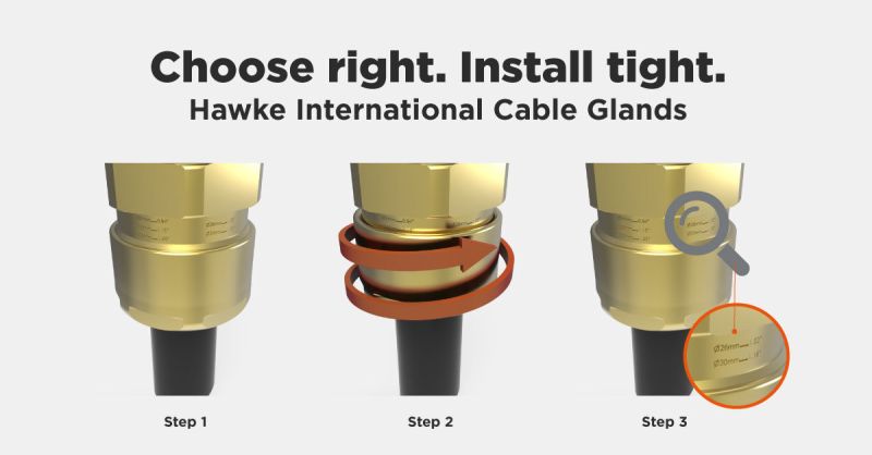
The cable gland is permanently marked with various lines/numbers indicating the correct tightening level related to the cable diameter. Following the relevant cable gland Installation Instructions, the back seal should be tightened until a seal is formed on the cable outer sheath and then tightened one further turn
5. Final Cable Gland Checks
-
Confirm ingress protection (IP rating)
-
Check earth continuity for armoured installations
-
Inspect for visible damage or loose components
Common Installation Mistakes to Avoid
-
❌ Using the wrong gland type for the cable
-
❌ Over-tightening or under-tightening
-
❌ Incorrect sequence of gland components
-
❌ Poor cable preparation or incorrect stripping of cable
-
❌ Forgetting to earth the armour
What Makes Hawke Glands Different?
Hawke’s range of cable glands are globally recognised for their robust construction, Ex-rated safety, and easy-to-install designs.
Whether it’s Ex d (flameproof), Ex e (increased safety), or Ex nR (restricted breathing), Hawke has a solution that safeguards your installation integrity—whatever the environment.
Need Support Choosing the Correct Cable Gland?
At Thorne & Derrick, we help you get it right the first time. As trusted Stockists & Distributors of Hawke cable glands, we provide:
-
Technical support
-
Product selection advice
-
Same-day dispatch for stocked cable gland items
Contact our team today or explore our full range of Hawke cable glands.

Interface F Bushings & High Voltage Power Cable Connectors
April 23rd, 2025Author | Rialdo Suwandi
Founder at Aldora Electric | Expert in Renewable Electrical Engineering & Cable Systems | Problem Solver | FIEAust CPEng NER

HV Bushings & Connectors
What Are Interface F Bushings?
How Do To Select the Right Cable Connector?
As medium voltage (MV) power systems grow in scale and capacity, manufacturers have introduced electrical equipment, such as transformers and switchgear, capable of handling up to 1250A at 52kV and 2500A at 36kV.
To ensure interoperability across manufacturers, these Interfaces are standardised under EN 50180 and EN 50181 as Interface F Bushings.
Furthermore, EN 50673 standardises 630A and 1250A bushings at 72.5kV.
What Are Interface F Bushings Used For?
Interface F bushings are typically used to connect gas-insulated switchgear (GIS) and transformers to cable circuits using separable connectors distributing electrical power at 11kV, 33kV and up to 66kV – manufactured by Nexans Euromold the connectors are suitable for cable termination of polymeric (XLPE EPR) insulated cables with copper wire or copper tape screen, wire armoured (SWA/AWA), wire braided or unarmoured cables into MV-HV Electrical Equipment with Interface F bushings.
Advantages of Electrical Equipment Bushings
- Compact switchgear and transformer designs
- Interoperability across different manufacturers
Types of Interface F Bushings
As defined in EN 50180 and EN 50181:
F1 Bushings: Um ≤ 36 kV; Ir = 2500 A
F2 Bushings: Um ≤ 52 kV; Ir = 630 A
F3 Bushings: Um ≤ 52 kV; Ir = 1250 A
For 72.5kV high voltage power systems, EN 50673 defines the following:
F4 Bushings: Um = 72.5 kV; Ir = 630 A
F5 Bushings: Um = 72.5 kV; Ir = 1250 A
Note: F5 interfaces are commonly used in offshore wind applications but can adopted for large onshore installations as well.
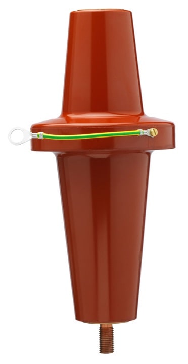
Pictured | Nexans Q900AR-1Q900AR-2 Interface F Equipment Bushing 52kV MV HV
How to Select the Right High Voltage Separable Connector for Interface F Bushings
To ensure proper fit and reliable performance the following information must be established:
Interface type? e.g. F1
Maximum system voltage? e.g. Um = 36kV
Cable insulation type? e.g. XLPE
Conductor material and cross-section? e.g. copper, 800sqmm
Insulation over-diameter? e.g. 52.8mm
Number of circuits per phase? e.g. 2 circuits
Are surge arresters required? Confirm via an insulation coordination study
Interface F bushings enable safe, standardised, and high-capacity MV cable connections to GIS, and transformers, both for on-shore and off-shore applications.
Selecting the correct separable connector Interface F Connector —matched to interface type, voltage, current, cable type, and system design—ensures long-term reliability, safety, and maintainability.
Definitions of International Electrical Standards
EN 50180 | This European Standard is applicable to ceramic and resin insulated bushings having highest voltages above 1kV up to 52kV, rated currents from 250A up to 3150 A and frequencies from 15 Hz up to 60 Hz for insulating liquid filled transformers. This European Standard establishes essential dimensions, to ensure interchangeability of bushings and to ensure adequate mounting and interchangeability of mating plug-in separable connectors of equivalent ratings.
EN 50181 | This European Standard is applicable to insulated bushings for maximum voltages above 1kV up to 52kV, rated currents from 250A up to 2 500A and frequencies from 15 Hz up to 60 Hz for equipment other than liquid filled transformers. This European Standard establishes essential dimensions, to ensure adequate mounting and interchangeability of mating plug-in separable connectors of equivalent ratings.
EN 50673 | Extend the scope of the EN50180-1/2/3 and EN50181 for plug-in type bushings up to 72.5 kV
Thorne & Derrick distribute the most extensive range of MV HV Medium & High Voltage Cable Joints, Terminations & Connectors from manufacturers including 3M, Prysmian, Nexans Euromold, Elastimold, Pfisterer CONNEX & SEANEX and Shrink Polymer Systems.

Lovink Cable Joints & Network Resilience at 11kV & 33kV
April 23rd, 2025Cable Jointing Solutions
Network resilience requires advanced technology solutions manufactured from highest performance materials; if high harmonics, Sine wave distortion, AD8 protection, abnormal thermal cycling, high-water table, ALE of legacy PILC or general cable failure prevention to critical 11/33kV circuits matters to you, then talk to us.
- UK DNO Compliance (G81) & Contestable Connections (including NGED)
- High Water Table, Submersible, Seawater Resistant & Flood Zone Installations
- Mechanical Protection for Heavy Industrial Applications
- Asset Life Extension of Legacy Paper-Insulated Cables (PILC / PICAS)
- High Harmonics & Non-Linear Loads (Sags & Swells)
- Sine-Wave Distortion & Power Quality Improvement
- Abnormal Thermal Cycling in “High-Load / Low-Load” Systems
- Flame-Free Installation for Potentially Explosive Atmospheres
Where cables undergo dynamic cyclical load in high harmonic and non-linear load applications the Lovink range of cable joints demonstrate years of fault-free field performance in high temperature installations – additionally, the cable joints are “flame-free” and therefore safe for installation in potentially explosive atmospheres as no heating source or naked flame is required for the installation.
Resin encapsulation provides the highest levels of mechanical impact protection and electrical insulation eliminating voids, discharges and ionisation within the cable joint – the seawater resistant resin and “wet area” (2 bar at 20m water head) performance counters premature electrical cable joint failures in the renewable sector where damp soil conditions, flooded duct and water immersion can induce premature service failure to jointing solutions utilising other technologies.
The compact design permits reduced size joint holes reducing excavation and associated civil engineering preparation costs – ideal for confined space applications where volume displacement is a factor and close quarter working necessitates a compact profile solution.
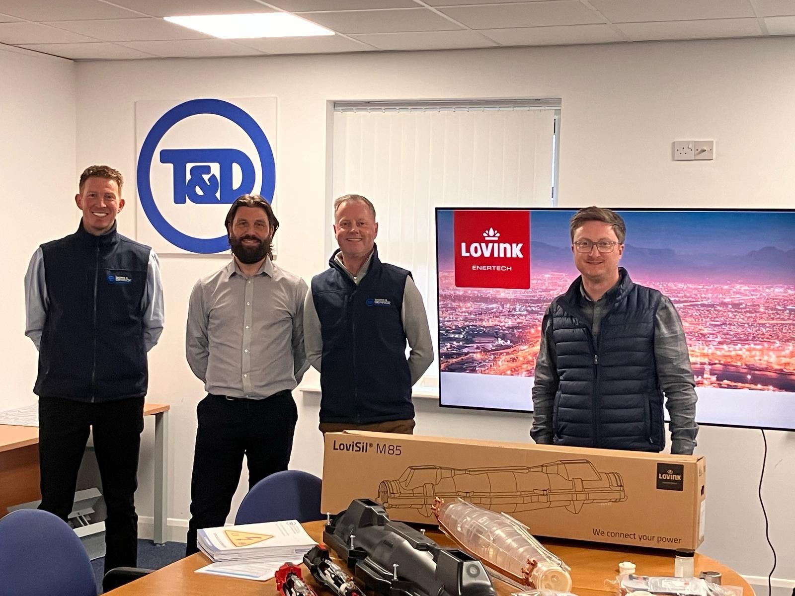
Thank you to Stephen Davies (Lovink Enertech Account Manager) for todays emphatic Presentation and roundtable with our incredible Team.
High Water Table Cable Connections
up to 2Bar (20m) Water Table
Lovink Cable Joints
Water ingress is one of the most common causes of failure in underground cable networks.
Once moisture reaches a cable joint in waterlogged soils, flooded areas or cable pits, the risk of failure increases significantly.
So how do you ensure a connection remains properly sealed in waterlogged conditions?
The LoviX® R70 Straight Joint uses a cold shrink design combined with a fully sealed resin system, enabling a consistent and pressure-resistant seal, with testing up to 2 bar water pressure.
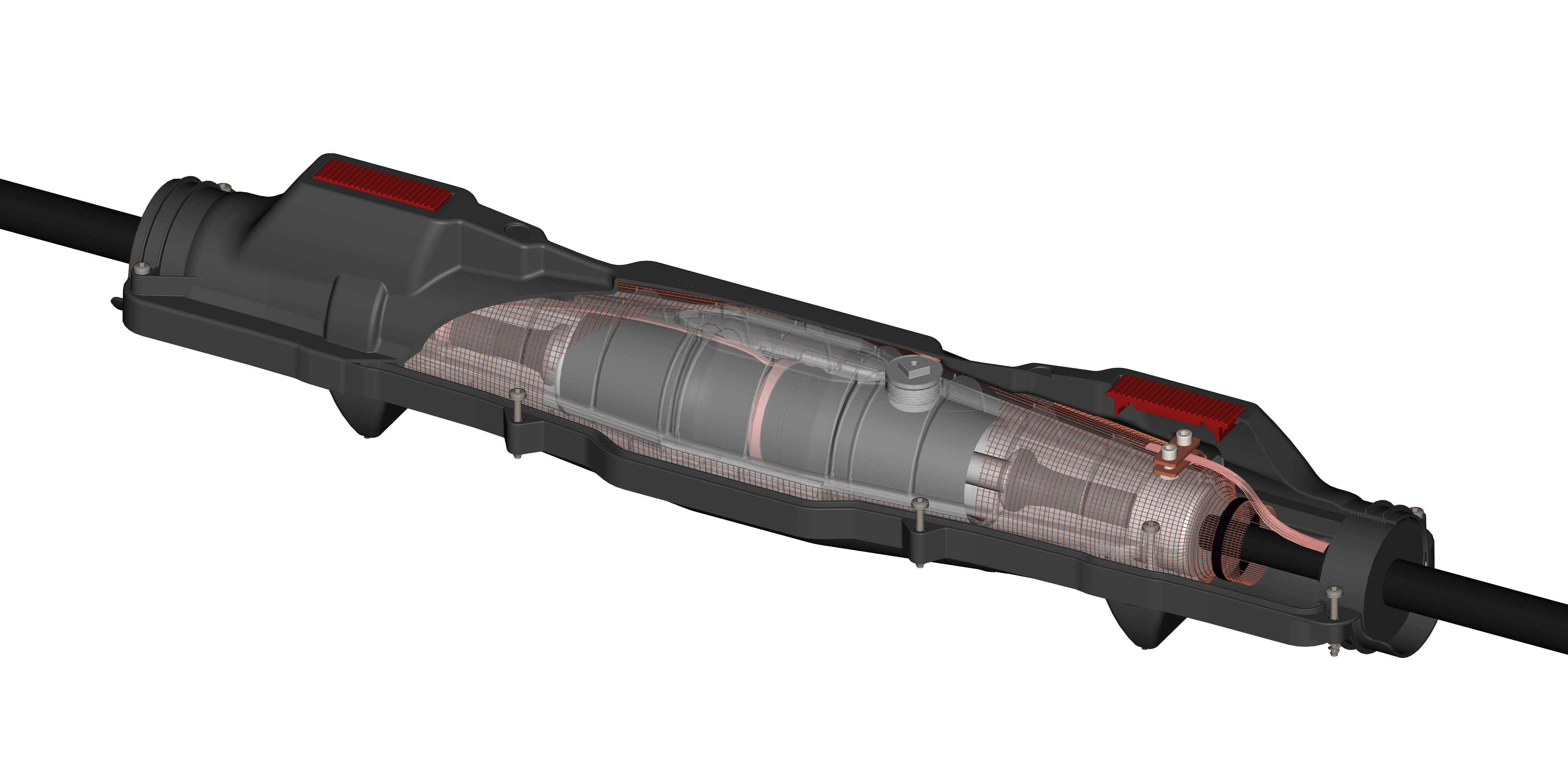
For straight, transition and branch connections of MV Power Cables – this includes 11kV and 33kV paper-insulated (PILC/PICAS) and polymeric (XLPE/EPR) cables up to 1000sqmm.
The Lovisil range of water proof cable joints provide excellent continued service for Medium & High Voltage Cables in flooded cable trenches, underground cable ducts and general wet-conditions associated with high-water table applications with a Type-Test documented to 2 Bar water pressure; typically used to fault repair, divert and extend single and 3-core cables with XLPE, EPR and PILC insulation with 11kV 24kV 33kV voltage classification.
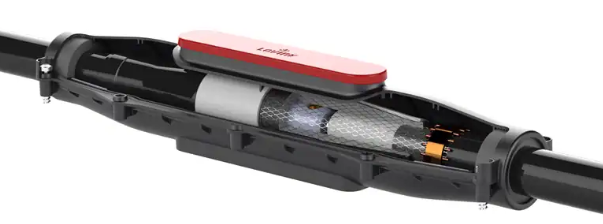
Cable Joints for Medium & High Voltage Cables | the Lovink range of cable joints provide high-performance for high-challenge applications including configurations for straight, transition, branch and loop jointing of cables typically distributing electricity at 11kV, 24kV and 33kV; this includes connection joints for extensions and repairs for MV HV cables with XLPE, PILC & EPR insulation.
The Lovisil range of water proof cable joints provide excellent continued service for Medium & High Voltage Cables in flooded cable trenches, underground cable ducts and general wet-conditions associated with high-water table applications with a Type-Test documented to 2 Bar water pressure; typically used to fault repair, divert and extend single and 3-core cables with XLPE, EPR and PILC insulation with 11kV 24kV 33kV voltage classification.
Lovink Cable Joints
Thorne & Derrick | Specialist Distributors | HV Cable Accessories
CSD Sealing Systems for Critical Fire Protection of Substations
April 23rd, 2025From CSD Sealing Systems
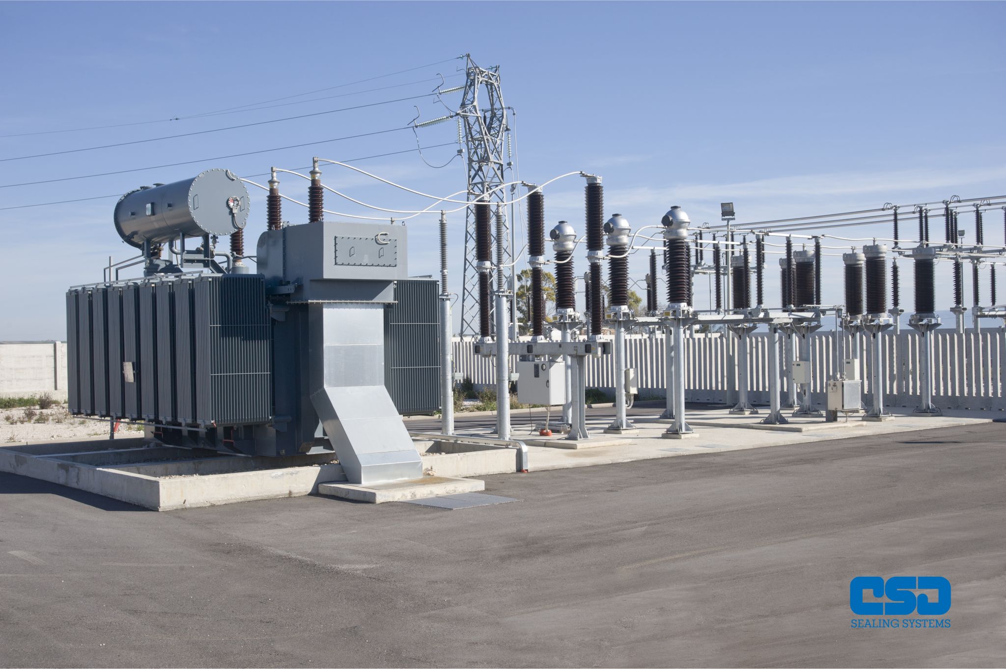
The recent fire at the electrical substation next to Heathrow Airport, which led to its temporary closure and disrupted thousands of flights reminds the industry of the importance of critical fire protection measures in substation environments.
Thorne & Derrick are Approved Main UK Distributors for CSD Sealing Systems, specialising in advanced cable duct sealing solutions designed to enhance the safety and resilience of electrical substations.
The CSD Sealing Systems range of products, including the NOFIRNO range are engineered to prevent the spread of fire, smoke, and water, thereby safeguarding essential infrastructure and minimising the risk of catastrophic failures.
By integrating CSD’s pipe and duct sealing technologies, substation operators can significantly reduce the potential for fire-related disruptions, ensuring continuous operation and protecting both assets and the public.
Critical Fire Protection of Substations


