

Blog
Arc Flash Study: Is It A Legal Requirement?
September 20th, 2019

Andrew Linley, Compliance Director at Electrical Safety UK Limited
The following article about the need to carry out an Arc Flash Study has been produced by Andrew Linley, Compliance Director at Electrical Safety UK Limited. Special thanks for the permission to re-publish your article.
Andrew has vast experience in electrical installation, maintenance and the requirements and the practicalities of electrical inspection, testing and certification. At Electrical Safety UK Limited, they provide expert consultancy and advice for organisations across Europe concerned with the safe management of risk associated with all electrical work activities.
Is arc flash study a legal requirement?
The simple answer is yes…
An arc flash study needs to be carried out by an electrical safety expert, to determine hazards and risks in electrical systems. The need to carry out a suitable and sufficient risk assessment, and to put measures in place to protect those who could be put at risk, is mandated by the following regulations:
- Regulation 4(1) – the Electricity at Work Regulations 1989
- Regulation 3(1) – the Management of Health and Safety at Work Regulations 1999
Regulations
Regulation 4(1) of the Electricity at Work Regulations 1989 states ‘All systems shall at all times be of such construction as to prevent, so far as is reasonably practicable, danger’.
Regulation 2(1) of the same regulations defines danger as meaning the risk of injury and ‘injury means the death or personal injury from electric shock, electric burn, electrical explosion or arcing, or from fire or explosion initiated by electrical energy, where any such death or injury is associated with the generation, provision, transmission, transformation, rectification, conversion, conduction, distribution, control, storage, measurement or use of electrical energy’.
Electricity poses arc flash hazards, and the risks posed are electric shock, burns, fires, arcing and explosion.

We demonstrate the need for Arc Flash Study and Arc Flash Protection
Regulation 3(1) of the Management of Health and Safety at Work Regulations 1999 states ‘every employer shall make suitable and sufficient assessment of (a) the risks to the health and safety of his employees to which they are exposed whilst they are at work; and (b) the risks to the health and safety of persons not in his employment arising out of or in connection with the conduct by him of his undertaking, for the purpose of identifying the measures he needs to take to comply with the requirements of and prohibitions imposed upon him by or under the relevant statutory provisions and by Part II of the Fire Precautions (Workplace) Regulations 1997’.
Conducting arc flash studies
It has been established that we need to conduct arc flash studies of the workplace to determine risks and hazards, but how exactly are they conducted?
The on-site evaluation results in fault current and coordination analysis, fault equipment labelling, recommendations for improvements and requirements for PPE (Personal Protective Equipment). An arc flash study can be carried out by several organisations, including Electrical Safety Uk Ltd.
Further reading
Electrical Safety UK Ltd
Electrical Safety Management is our core business. We provide expert consultancy and advice for blue chip organisations across Europe concerned with the safe management of risk associated with all electrical work activities. ESUK provide a multi-faceted holistic approach including a full electrical safety management program, project management and policy documentation all bespoke to the client’s requirements including fully accredited and bespoke training courses and personnel assessment programmes.
Here at Electrical Safety UK, our team delivers a range of professional services to customers in a variety of market sectors. The team prides itself on the quality of the services it delivers to companies at the heart of manufacturing, engineering, energy, food production and education in the UK and Europe.
Visit Website: https://www.elecsafety.co.uk/
ESUK Services include:
1 Electrical Safety Management – Specialist consultancy and advice concerned with the safe management of risk associated with all electrical work activities. ESUK offer a multi-faceted approach including a full electrical safety management program, full project management and policy documentation bespoke to a client’s requirements.
2 Electrical System Studies – ESUK is the UK’s foremost exponent of Arc Flash Technology and carry out a wide range of power system studies, including Fault Level Analysis to IEC and ANSI standards, Protection Coordination, and complex Arc Flash Risk Assessments.
3 Training – ESUK offer both accredited and bespoke training courses including City & Guilds, IOSH, Safety Pass Alliance, Energy and Utility Skills. ESUK are also registered with the EEIAS and CIPD for recognition and accreditation of bespoke training courses.
Contact Details
Electrical Safety (UK) Limited
2 Genesis Business Park
Sheffield Road
Rotherham
S60 1DX
Tel: 0800 652 1124
Tel: 01709 961 666
Email: [email protected]
Thorne & Derrick
Thorne & Derrick are national distributors of LV, MV & HV Cable Installation, Jointing, Substation & Electrical Equipment – servicing businesses involved in cabling, jointing, substation, earthing, overhead line and electrical construction at LV, 11kV, 33kV, 66kV and EHV. Supplying a complete range of power cable accessories to support the installation and maintenance of low/medium and high voltage power systems:
- Slip-on Cable Terminations
- Cold-shrink Cable Terminations
- Heat-shrink Cable Terminations
- Cable Joints – Heat & Cold-shrink
- Separable Connectors (Euromold)
- Surge Arresters & Switchgear/Transformer Bushings
Key Product Categories: Duct Seals | Cable Cleats | Cable Glands | Electrical Safety | Arc Flash Protection | Cable Jointing Tools | Cable Pulling | Earthing | Feeder Pillars | Cable Joints LV | Joints & Terminations MV
Arc Flash Learning & Resources

Thorne and Derrick are proud to be distributors of ProGARM arc flash coveralls and protection.
We can help – should you require arc flash calculators or advice on the type of clothing and protection available please do not hesitate to contact us.


Cable Replacement, Splicing & Terminating : A Video Tutorial
September 19th, 2019

Martha Davis
The following cable replacement tutorial has been republished with kind permission of Martha Davis (Senior Director of Content – T&D World and Utility Analytics Institute) from Transmission & Distribution World and their video sponsor Burns & McDonnell.
Burns & McDonnell is a full-service engineering, architecture, construction, environmental and consulting solutions firm, based in Kansas City, Missouri.
Participating Utility: Kansas City Power & Light (KCP&L).
Transmission & Distribution World’s mission is to provide utility executives, managers, engineers, supervisors, operators and linemen with must-read information on:

- Design
- Engineering
- Construction
- Operation
- Maintenance of the Electric Power-Delivery Systems
This includes an in-depth understanding of transmission, distribution, substations, automation and power flow control.
Want to learn how to perform tasks in the field?
T&D How videos are real-life and shot-on-site, showing transmission and distribution crews and cable splicers at work.
cable replacement project begins
Video: Kansas City Power & Light (KCP&L) crews begin a cable replacement project at the Meritex Caves in suburban Kansas City.
In Part 1, the crew installs new cable between an above-ground enclosure and a three-phase distribution pole. The linemen crew in the bucket truck prepare a copper cable feed from overhead to underground – a boom is used to enable a vertical cable lift by attachment to a wire mesh Kellem cable grip. The cable pull positions the cable onto the pole. An Altec cable pulling frame supports the cable pull into the underground cable duct.
Cable Replacement | termination
Video: In Part 2 we watch crews install a new di-electric switch in the caves below ground and pull cable from above ground, then create new splices into the switch.
See the engineers use “noisy sticks” to provide electrical safety check procedures for voltage detection and isolate the high voltage switching cubicles. The solid-dielectric-in-air fault interrupting switch is positioned for the cable splicer to commence cable termination.
The cable termination process starts with the “tamping down” of the neutrals prior to sliding on the cold shrink tube and separable tee-connector cable termination. Semi-conductor insulation is peeled back and cable insulation cut away with the aid of a heat shrink gas torch to soften the insulation layer. Compression style crimp lugs are terminated onto the cable using battery crimping tools as the cable is connected to the switch.
cable splicing
Video: In Part 3 a splicing crew installs new splices at the enclosure feeding power from the distribution pole to the caves underground.
See the cable splicer working 6 cables into the enclosures from the pole – peeling back the cable outer jacket on the concentric neutrals and installing protective water-sealing mastic and cold shrink. Clearances are measured and heat source used to expose cable imperfections, such as cuts, which can then be located and removed by sanding.
The medium voltage cable is terminated to the neutral busbar using separable elbow tee-connectors. Dummy caps are installed and used to test the ground wires.
3m scotch tape for electrical insulation

Video: In Part 4 crews go up on the distribution pole to create new splices and secure the grounding wire.
The distribution pole has been re-cabled and ready for connection as the cable phases are designated A, B and C by the linemen/splicers and prepared for termination.
The cable semi-con is stripped, cable lug depths measured, heat applied to the cable, insulation surfaces cleaned and sanded and cold shrink applied.
Watch the electrical taping techniques of the experienced cable jointer using 3M Scotch 33 tape to provide electrical insulation layers to the cable – neutral tails are taped up and switches opened up to begin the cable connection.

💡 Some 3M Scotch Electrical Tapes Tips & Skills….
closing the switches
Video: In Part 5 the crew adds jumpers and closes the switches to energise the line, bringing power from above ground to 80 feet under in the Meritex Caves, using new and larger cable to meet increased electrical demand.
Watch the linemen and cable splicers “running the tops”, use “pelicans” (hotline clamps) and wire brushes to clean thoroughly. Fault indicators are applied and “beat-on” wedge connectors installed by hammer. The “pelicans” are connected to the switch pins and a drop-out wire installed down from the arrester. Lastly, cable tags are used to provide identification to the medium voltage cables allowing energisation of the cable once switches are closed using switch sticks.

Press Release | Thorne & Derrick Appointed Approved Stockist for UK Leading Cable Pulling Equipment Manufacturer
Thorne & Derrick are national distributors of LV, MV & HV Cable Installation, Jointing, Substation & Electrical Equipment – servicing businesses involved in cabling, jointing, substation, earthing, overhead line and electrical construction at LV, 11kV, 33kV, 66kV and EHV. Supplying a complete range of power cable accessories to support the installation and maintenance of low/medium and high voltage power systems:
- Slip-on Cable Terminations
- Cold-shrink Cable Terminations
- Heat-shrink Cable Terminations
- Cable Joints – Heat & Cold-shrink
- Separable Connectors (Euromold)
- Surge Arresters & Switchgear/Transformer Bushings
Key Product Categories: Duct Seals | Cable Cleats | Cable Glands | Electrical Safety | Arc Flash Protection | Cable Jointing Tools | Cable Pulling | Earthing | Feeder Pillars | Cable Joints LV | Joints & Terminations MV HV

Tis A Good Day In Twitter World When……………..
September 19th, 2019‘Tis a good day in twitter world when @ThorneanDerrick follow you pic.twitter.com/8ugI6pzZ3Y
— Paul Meenan (@Sparky_Jedi) September 17, 2019

Follow Paul Meenan
THORNE & DERRICK
Thorne & Derrick are national distributors of LV, MV & HV Cable Installation, Jointing, Substation & Electrical Equipment – servicing businesses involved in cabling, jointing cables, substation, earthing, overhead line and electrical construction at LV, 11kV, 33kV, 66kV and EHV. Supplying a complete range of power cable accessories to support the installation and maintenance of low/medium and high voltage power systems:
- Slip-on Cable Terminations
- Cold-shrink Cable Terminations
- Heat-shrink Cable Terminations
- Cable Joints – Heat & Cold-shrink
- Separable Connectors (Euromold)
- Surge Arresters & Switchgear/Transformer Bushings

Key Product Categories: Duct Seals | Cable Cleats | Cable Glands | Electrical Safety | Arc Flash Protection | Cable Jointing Tools | Cable Pulling | Earthing | Feeder Pillars | Cable Joints LV | Joints & Terminations MV HV
US02 Utility Cable Tool for Semi-Con Shaving MV HV Cables by Ripley
September 17th, 2019
US02 Utility Cable Tool for Semi-Con Shaving MV HV Cables by Ripley
US02 UTILITY Cable Tool
The new Ripley US02 adjustable cable semi-con shaving tool quickly and easily removes bonded semi-conductor layers from MV to HV power cables (5kV to 33kV) on end and mid span cable preparations.
The Ripley Tool’s compact and adjustable design accommodates a wide range of cable diameters (18 to 60mm) and semi-conductor thickness of up to 2.4mm.
The unique blade shape preserves the smooth surface on MV-HV cable insulation, eliminating the need for deburring or additional surface finishing – the optimal stability design of the cable jointing tool securely supports cables with diameters from 0.71″ to 2.36″ (18 mm to 60 mm) throughout the shaving operation.
The cable cutting blade depth is easily adjustable in increments of .1″ to achieve the perfect depth.
The US02’s unique blade shape provides a smooth surface finish with a bevelled semi-con edge and eliminates the need for any additional features.
Engineered to improve workplace safety and cable preparation the US02 tool replaces the use of traditional cable jointers knives. The cable tool is ergonomic in design and increases efficiency by providing greater leverage and reducing hand strain.
Multiple contact bearings securely cradle the cable and provide stability throughout the shaving operation to ensure accuracy for preparing cables prior to jointing and termination.
Four speed positions optimise performance and a stop position easily squares of the edge without the need for an additional clamp. If necessary the factory set blade can be quickly and easily replaced.
The Utility Tool US02 is the fastest, safest and most accurate tool for removing bonded semi-con from MV HV power cables.

Ripley US02 Utility Cable Tool
US02 Utlity Cable Tool
Features & Benefits
- Compact design accurately removes semi-con within 1.18″ (30 mm) of the jacket on mid-span and end stripping applications
- Precision blade depth adjusts in increments of 0.004″ (0.1 mm)
- Adjusts for 0.71″ to 2.36″ (18 mm to 60 mm) cable diameters with semi-con thicknesses up to 0.095″ (2.4 mm)
- A revolving ergonomic handle & accessible adjustment knobs reduce effort & potential strain from repetitive shaving functions
- Stop position squares off the edge to complete the shaving operation without the need for an additional clamp
- Factory-set blade is easily replaced
| Cable Compatibility | Primary Distribution Underground |
| Cable Access | Mid-Span, End |
| Min. Cable Outer Diameter | 0.71″ (18 mm) |
| Max. Cable Outer Diameter | 2.36″ (60 mm) |
| Min. Voltage | 5 kV |
| Max. Voltage | 35 kV |
| Insulation Thickness | Up to 0.095″ (2.4 mm) |
| Material | Aluminum |
| Length | 6″ (152.4 mm) |
| Weight | 1 lb 8.6 oz (698.5 g) |
| Replacement Blade Part # | US02-7501 |
Compatibility
| Tool Part Number | Cable Voltage | Cable Size ø | Semi-con Thickness | Chamfer Angle | Replacement Blade Part |
| US02 | 5kV to 35kV | 0.71″ to 2.4″ (18 to 60 mm) | Up to 0.095″ (2.4mm) | 12″ | US02-7501 |
 |
 |
 |
 |
| Unique blade shape leaves surface of insulation extremely smooth | Extra rollers provide tool stability on a range of cable sizes | Winding pin keeps semi-con strip from getting in the way | Equipped with four speed positions to optimise performance |
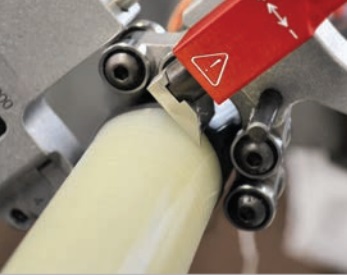
RIPLEY US02 OPERATING INSTRUCTIONS
- The cable jointer should retract the cutting blade to its highest position by turning the blade adjusting knob counterclockwise
- Open the cable tool and locate the cable end at the taper transition on the blade. Secure the cable in the tool (Fig. 2a, 2b)
- Turn the blade adjusting knob clockwise until the blade touches the semi-con screen of the MV HV cable
- Set the feed lever into a stripping position. #1 is a conservative feed
- Rotate the tool on the cable. As the tool advances on the cable, observe the semi-con chip and re-adjust the blade depth for a minimal thickness of insulation removal and an optimal shaving result
- The feed lever can be re-positioned diagonally toward the #2 for a more aggressive feed or fully at the #2 for the fastest feed. The feed can be backed down by moving the lever diagonally toward the Stop position
- Observe the shaved semi-con strip during operation. During the shaving process, do not allow the strip to get caught under the cable rollers. This will disturb the shaving result. A convenient technique is to wind the shaved semi-con strip around the tool bar handle while shaving (Fig.3)
- Another option is to guide the strip around the shaved insulation using the winding pin. (Fig.4)
- After shaving to the desired length, move the feed lever to the stop position. Make one full turn to finish the shaving. Remove the tool from the cable

Ripley US02-7000 Operating Instructions
Thorne & Derrick
Thorne & Derrick are national distributors of LV, MV & HV Cable Installation, Jointing, Substation & Electrical Equipment – servicing businesses involved in cabling, jointing, substation, earthing, overhead line and electrical construction at LV, 11kV, 33kV, 66kV and EHV. Supplying a complete range of power cable accessories to support the installation and maintenance of low/medium and high voltage voltage power systems:
- Slip-on Cable Terminations
- Cold-shrink Cable Terminations
- Heat-shrink Cable Terminations
- Cable Joints – Heat & Cold-shrink
- Separable Connectors (Euromold)
- Surge Arresters & Switchgear/Transformer Bushings
Key Product Categories: Duct Seals | Cable Cleats | Cable Glands | Electrical Safety | Arc Flash Protection | Cable Jointing Tools | Cable Pulling | Earthing | Feeder Pillars | Cable Joints LV | Joints & Terminations MV
Transient Recovery Voltage (TRV) in Interruption of Small Inductive Currents by Circuit Breakers
September 17th, 2019
In this Guest Article, we discuss TRV (Transient Recovery Voltage) for high-voltage circuit breakers.
➡ The following article has been written by Ali Sepehri from Switchgear
Ali Sepehri is a qualified and experienced Switchgear Sales Engineer and technical authority.
He has a remarkable understanding of all the engineering concepts and has been working for more than 15 years in different aspects of the engineering process including sales engineering, production, development and research in high voltage and medium voltage circuit breakers and disconnector switch and gas-insulated switchgear (GIS).

Transient Recovery Voltage
Transients caused by switching operations in linear systems can be analyzed by using the superposition principle. The switching process caused by an opening operation is obtained by adding the steady-state solution, which exists prior to the opening operation, and the transient response of the system that results from short-circuiting voltage sources and open-circuiting current sources to a current injected through the switch contacts.
Since the current through the switch terminals after the operation will be zero, the injected current must equal to the current that was flowing between switch terminals prior to the opening operation. When the contacts of a switch start to open a transient voltage is developed across them. This voltage, known as TRV, is present immediately after the current zero and in actual systems, its duration is in the order of milliseconds.
A good understanding of the transient phenomena associated with circuit breaker operations in power systems has led to improved testing practice and resulted in more reliable switchgear. Recommended characteristic values for simulation of the TRV are fixed in standards.
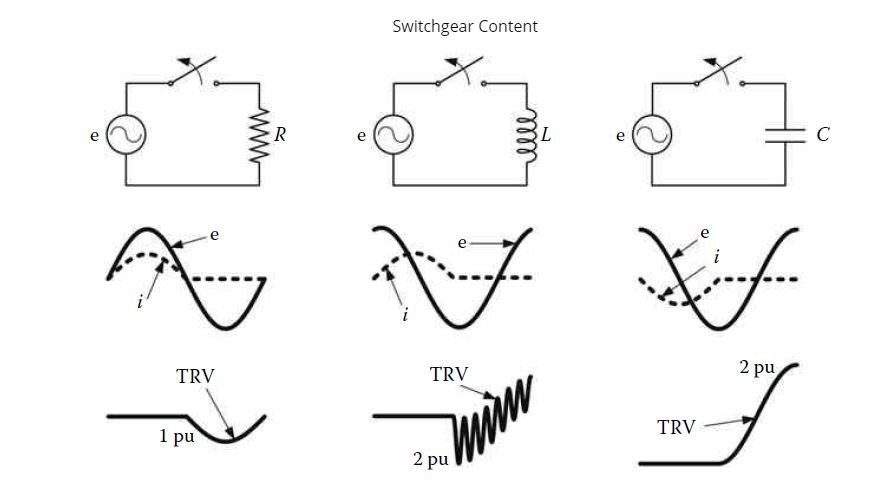
In the Figure below you see TRV circuit breaker terminals when interrupting the current in very simple circuits. Observe the different waveshape that appear in each case. The representation of each circuit is that depicted in the figure, except for the interruption of the inductive current since in this case the current zero occurs when the voltage across the inductor terminals is maximum, and a capacitive element is needed to account for the trapped charge. The latter oscillation is caused by the energy transfer between the inductor and the capacitor. Although real systems are much more complex than the circuits analyzed above, these cases show that switching under normal operating conditions can be categorised as resistive, inductive, and capacitive.
The interruption of small currents can lead to situations that are known as current chopping and virtual chopping. If the current is interrupted at current zero, the interruption is normal and the TRVs are usually within the specified values. However, if a premature interruption occurs, due to current chopping, the interruption will be abnormal and it can cause high-frequency reignitions and overvoltages.
When the breaker chops the peak current, the voltage increases almost instantaneously, if this overvoltage exceeds the specified dielectric strength of the circuit breaker,re-ignition takes place. When this process is repeated several times, due to high-frequency reignitions, the voltage increase continues with rapid escalation of voltages. The high-frequency oscillations are governed by the electrical parameters of the concerned circuit, circuit configuration and interrupter design, and result in a zero-crossing before the actual power-frequency current zero.
In the figure below compares the load side voltage and the TRVs that are generated when arc interruption takes place at current zero and before current zero (current chopping), respectively. It is obvious from this example that the second case is more severe. The importance of current chopping can be easily understood by neglecting the influence of losses at the load side. After current interruption at current zero, the energy stored in the load side is the energy stored at the capacitance, whose voltage is at the maximum.

a) Equivalent circuit. (b) Arc interruption at current zero. (c) Arc interruption before current zero.
In the case of current chopping, the instability of the arc around current zero causes a high-frequency transient current to flow in the neighbouring network elements. This High-Frequency current superimposes on the power-frequency current whose amplitude is small and which is actually chopped to zero. In the case of virtual chopping, the arc is made unstable through a superimposed high-frequency current caused by oscillations with the neighbouring phases in which current chopping took place. Virtual chopping has been observed for gaseous arcs in air, SF6, and oil.
Vacuum arcs are also very sensitive to current chopping.
The phenomena of chopping and reignition, with associated high-frequency oscillatory overvoltages, are attributed to the design of the circuit breaker.
Circuit breakers are designed to cope with high fault currents. If a design is concentrated only on an efficient performance for high currents, it will be also efficient for small current and will try to interrupt before the natural current zero. This may produce current chopping and reignitions with adverse consequences. The breaker design should incorporate features to cope equally well with small and high currents.

Arc Flash Protection | Polo Shirts | Jackets | Coveralls | Trousers | Helmets | Gloves
Further Reading
- Separable Connectors For Eaton Xiria MV HV Switchgear RMU (Ring Main Unit)
- Bushings & Connectors – How To Select & Specify Switchgear & Transformer Connectors
- MV Switchgear GIS Connectors Type Use With Ormazabal CGMCOSMOS
- Euromold 400LR 33kV Connections Into Ormazabal MV Switchgear
- 33kV Terminations – ABB SafePlus Switchgear Cable Connectors (BS7870/4.1 XLPE Cable)
THORNE & DERRICK
Thorne & Derrick are national distributors of LV, MV & HV Cable Installation, Jointing, Substation & Electrical Equipment – servicing businesses involved in cabling, jointing, substation, earthing, overhead line and electrical construction at LV, 11kV, 33kV, 66kV and EHV. Supplying a complete range of power cable accessories to support the installation and maintenance of low/medium and high voltage power systems.
Switchgear Cable Terminations
- Slip-on Cable Terminations
- Cold-shrink Cable Terminations
- Heat-shrink Cable Terminations
- Cable Joints – Heat & Cold-shrink
- Separable Connectors (Euromold)
- Surge Arresters & Switchgear/Transformer Bushings
Key Product Categories: Duct Seals | Cable Cleats | Cable Glands | Electrical Safety | Arc Flash Protection | Cable Jointing Tools | Cable Pulling | Earthing | Feeder Pillars | Cable Joints LV | Joints & Terminations MV HV

MV HV – Medium & High Voltage Cable Joints, Terminations & Connectors (11kV 33kV EHV)
