

Blog
Cable Sealing Ends Explained | HV Substation Cable Terminations
June 16th, 2026
Cable sealing ends are high voltage cable accessories used to terminate, seal and connect power cables at the end of a cable circuit. They are commonly used where underground cables connect to substations, overhead lines, transformers, switchgear, GIS equipment or other high voltage electrical infrastructure.
In simple terms, a cable sealing end provides the controlled transition between a high voltage power cable and the equipment or network it connects into. It must manage electrical stress, maintain insulation performance, protect against environmental conditions and provide a safe, reliable interface for the cable system.
For MV, HV and EHV cable networks, sealing ends are not just connection points. They are critical parts of the cable system, especially on 66kV, 132kV and higher voltage installations where cable preparation, insulation coordination, earthing, sheath bonding and installation quality directly affect long-term network reliability.
Thorne & Derrick supply HV cable joints, terminations and connectors for medium and high voltage cable systems, including 66kV cable sealing ends and 132kV cable sealing ends.
Quick Answer: What Is A Cable Sealing End?
A cable sealing end is a high voltage cable accessory used at the end of a power cable circuit to terminate the cable and provide a sealed, electrically controlled interface to equipment such as switchgear, transformers, overhead lines or GIS substations.
In substation and transmission applications, cable sealing ends are commonly used on 66kV, 132kV and EHV cable systems. They help control electrical stress, maintain insulation integrity, protect the cable end from moisture and contamination, and provide a reliable connection between the cable and the wider power network.
What Is A Cable Sealing End?
A cable sealing end is the end termination assembly of a high voltage power cable. It is used where the cable has to connect safely into another part of the electrical network.
This could be:
- An outdoor substation termination connecting an underground cable to overhead equipment.
- A GIS sealing end connecting a cable into gas insulated switchgear.
- A transformer cable termination connecting the cable to transformer equipment.
- An overhead line transition where an underground cable circuit connects to an overhead line system.
- A cable sealing end compound where underground cable circuits are terminated before connection to external plant.
Unlike a simple low voltage cable termination, an HV cable sealing end must manage complex electrical and mechanical requirements. High voltage cable systems include multiple layers such as the conductor, conductor screen, insulation, insulation screen, metallic sheath, outer sheath and bonding arrangements. The sealing end must be compatible with the cable construction and the equipment it connects to.
For 66kV and 132kV systems, the cable sealing end is usually selected as part of the complete high voltage cable accessory package, together with joints, terminations, sheath bonding equipment, surge protection, earthing arrangements and specialist cable jointing tools.
Where Are Cable Sealing Ends Used?
Cable sealing ends are used wherever a high voltage cable circuit needs to be safely terminated and connected into another asset.
Typical applications include:
- Transmission substations – connecting underground cable circuits to busbars, overhead lines, switchgear or transformers.
- Distribution substations – terminating medium and high voltage cable circuits at electrical equipment.
- GIS substations – connecting cables into gas insulated switchgear using GIS-compatible sealing ends.
- Cable sealing end compounds – terminating underground cable circuits before transition to overhead line routes.
- Wind, solar and battery storage grid connections – terminating export cable circuits at substations and grid interface points.
- Industrial power systems – terminating high voltage cable circuits into transformers, switchboards or motors.
- Offshore and onshore energy projects – connecting high voltage cables to substations, turbines, switchgear and export cable systems.
Cable sealing ends are especially important where the cable termination is exposed to outdoor weather, pollution, UV radiation, high electrical stress, mechanical loading or interface requirements with specialist equipment.
Cable Sealing End vs Cable Termination
The terms cable sealing end and cable termination are closely related, and in some project contexts they may be used interchangeably. However, there is a useful distinction.
A cable termination is the general term for the accessory used to terminate a cable and connect it to equipment.
A cable sealing end is often used in higher voltage or substation contexts to describe the complete termination assembly that seals the cable end and provides the electrical interface to outdoor equipment, GIS equipment or overhead line infrastructure.
For broader product ranges, see cable terminations and HV cable joints, terminations and connectors.
Types Of Cable Sealing Ends
Different cable sealing ends are used depending on the cable voltage, cable construction, installation environment and equipment interface.
The correct sealing end must be selected according to the cable design, equipment interface, voltage rating, conductor size, insulation type, sheath arrangement, pollution level, creepage requirement, earthing system and installation environment.
Cable Sealing Ends In Substations
In substations, cable sealing ends are often used where underground cable routes enter the substation and connect into above-ground electrical infrastructure.
This may include:
- Cable sealing end compounds where underground cable circuits transition to overhead line routes.
- Outdoor termination structures where cables terminate into air insulated equipment.
- GIS cable bays where cables connect into gas insulated switchgear.
- Transformer connections where cable circuits connect to high voltage transformer terminals.
- Grid connection substations for renewables, battery storage, data centres and industrial power systems.
Substation cable sealing ends must be coordinated with the wider electrical design. This includes surge protection, earthing, cable sheath bonding, link boxes, phase spacing, structural support, mechanical loading and access for installation and maintenance.
For underground cable routes feeding substations, see also cable ducting, duct seals and HV cable sheath bonding.
SF6 & GIS Cable Sealing Ends
A GIS cable sealing end is used where a cable circuit connects into gas insulated switchgear. GIS equipment is compact and widely used in substations where space, reliability and environmental protection are important.
An SF6 cable sealing end is associated with cable interfaces into SF6 insulated equipment. The sealing end must provide the correct electrical, mechanical and sealing interface between the cable and the gas insulated equipment.
GIS and SF6 sealing end applications require careful coordination between:
- Cable manufacturer
- Sealing end manufacturer
- GIS or switchgear manufacturer
- Cable jointer or installation contractor
- Client, DNO, utility or asset owner
The interface must be technically compatible. This means the sealing end is not selected in isolation — it must match the cable system and the equipment it connects to.
66kV & 132kV Cable Sealing Ends
66kV and 132kV cable sealing ends are used on high voltage cable systems where the performance of the accessory is critical to the reliability of the network.
Thorne & Derrick supply 66kV straight cable joints, outdoor terminations and SF6 cable sealing ends and 132kV straight cable joints, outdoor terminations and SF6 cable sealing ends.
The higher the voltage, the more important correct accessory selection, cable preparation and installation competence become. At 66kV and 132kV, small errors in cable preparation, stress control, contamination control or installation procedure can have serious long-term consequences.
What To Check When Specifying Cable Sealing Ends
Selecting a cable sealing end requires complete technical information about the cable, equipment and installation environment.
The most reliable approach is to specify the cable sealing end using full cable data and equipment interface details, rather than working from voltage alone.
Cable Preparation & Jointing Tools
High voltage cable sealing ends require accurate cable preparation before installation. Cable layers such as the outer sheath, metallic screen, semi-conductive screen, insulation and conductor must be prepared carefully in line with the manufacturer’s installation instructions.
Specialist cable jointing tools are used to support this preparation, including tools for:
- Outer sheath removal
- Bonded semi-con screen removal
- Insulation stripping
- Chamfering and grooving
- Conductor preparation
- Sheath bonding and earthing preparation
For high voltage work, tools from manufacturers such as Alroc are used by cable jointers for the preparation of MV and HV cables before installing joints, terminations and sealing ends.
Correct tool selection matters because poor cable preparation can damage the insulation, semi-conductive layer or cable screen. That damage may not always be visible immediately, but it can affect long-term electrical reliability.
Pfisterer Connectors, Terminations & Cable Interfaces
Cable sealing ends often sit alongside other high voltage connection technologies, including separable connectors, bushings, surge arresters and plug-in cable terminations.
Pfisterer CONNEX connectors are used for MV and HV cable connections, including medium voltage plug-in systems, bushings and surge arresters. These systems are often used where compact, pluggable or equipment-specific cable interfaces are required.
Pfisterer products are relevant to this topic because they sit within the same wider high voltage accessory family as cable sealing ends, terminations and connectors.
Typical associated products include:
- MV and HV separable connectors
- Inner cone cable plugs
- Bushings
- Surge arresters
- Dry outdoor composite terminations
- Self-supporting dry cable terminations
View the full Pfisterer MV HV connector and termination range.
Common Cable Sealing End Specification Mistakes
Cable sealing ends are critical accessories, so specification mistakes can be costly. Common issues include:
- Specifying by voltage only – voltage is not enough; cable construction, conductor size and equipment interface are also required.
- Confusing duct seals with cable sealing ends – duct seals seal cable entries; cable sealing ends terminate high voltage cables.
- Ignoring cable sheath bonding – HV cable systems may require specific bonding arrangements, link boxes or SVLs.
- Overlooking pollution level – outdoor terminations may need extended creepage in polluted or coastal environments.
- Not checking GIS interface details – GIS sealing ends must match the equipment connection requirements.
- Using unsuitable cable preparation tools – incorrect tools can damage the cable insulation or semi-conductive screen.
- Not allowing for installation competence – 66kV and 132kV accessories require experienced HV jointers and controlled procedures.
- Failing to check data sheets and manufacturer instructions – accessory selection should be based on approved technical documentation.
For critical systems, the sealing end should be reviewed as part of the complete cable system design, not treated as an isolated product purchase.
Related HV Cable Accessory Products
Cable sealing ends are normally specified alongside other high voltage cable accessories and installation products.
- HV Cable Joints, Terminations & Connectors – medium and high voltage cable accessories for 11kV, 33kV, 66kV and 132kV systems.
- 132kV Cable Joints, Outdoor Terminations & SF6 Cable Sealing Ends – high voltage accessories for 132kV cable systems.
- 66kV Cable Joints, Outdoor Terminations & SF6 Cable Sealing Ends – accessories for 66kV high voltage cable circuits.
- Pfisterer CONNEX Connectors & Terminations – MV HV connectors, bushings, surge arresters and terminations.
- Cable Jointing Tools – tools for preparing MV and HV cables before installing joints, terminations and sealing ends.
- HV Cable Sheath Bonding – guide to solid bonding, single-point bonding and cross-bonding methods.
- Sheath Voltage Limiters – SVLs for protection of MV and HV cable sheaths.
Cable Sealing Ends FAQs
Q: What is a cable sealing end?
A: A cable sealing end is a high voltage cable accessory used to terminate, seal and connect the end of a power cable to equipment such as switchgear, transformers, overhead line plant or GIS substation equipment.
Q: What is a cable sealing end in a substation?
A: In a substation, a cable sealing end is used where an underground power cable terminates and connects to substation equipment, overhead line infrastructure, transformers or GIS switchgear. It provides the electrical and sealed interface between the cable and the equipment.
Q: Is a cable sealing end the same as a cable termination?
A: The terms are closely related. A cable termination is the general accessory used to terminate a cable. A cable sealing end is usually a high voltage termination assembly that also provides sealing and a controlled interface to outdoor equipment, GIS, switchgear or overhead line systems.
Q: What is an SF6 cable sealing end?
A: An SF6 cable sealing end is used where a high voltage cable connects into SF6 insulated equipment, such as gas insulated switchgear. The sealing end must provide the correct electrical and mechanical interface between the cable and the equipment.
Q: Where are 132kV cable sealing ends used?
A: 132kV cable sealing ends are used on high voltage transmission and grid infrastructure projects where 132kV underground cable circuits connect to substations, overhead lines, GIS equipment, transformer bays or outdoor termination structures.
Q: What information is needed to specify a cable sealing end?
A: To specify a cable sealing end, you need the system voltage, cable construction, conductor material, conductor size, insulation type, screen and sheath details, equipment interface, installation environment, bonding arrangement and any project-specific approval requirements.
Q: What tools are used to install cable sealing ends?
A: HV cable sealing end installation requires specialist cable preparation tools for sheath removal, semi-con screen removal, insulation stripping, chamfering, grooving and conductor preparation. The exact tooling depends on the cable construction and manufacturer installation instructions.
Q: Can cable sealing ends be used outdoors?
A: Yes. Outdoor sealing ends are specifically designed for external substation and overhead line interface applications. Outdoor suitability depends on the termination design, pollution level, creepage distance, weather exposure, UV resistance and installation conditions.
Conclusion
Cable sealing ends are essential high voltage cable accessories used to terminate, seal and connect power cables at substations, overhead line interfaces, GIS equipment, transformers and other network assets.
They are especially important on 66kV, 132kV and EHV cable systems, where correct specification, cable preparation, stress control, insulation performance and installation competence are critical to long-term reliability.
When specifying a cable sealing end, engineers should check the complete cable system: voltage, conductor size, cable construction, equipment interface, installation environment, sheath bonding, surge protection, jointing tools and manufacturer instructions.
Thorne & Derrick supply HV cable joints, terminations, connectors and cable sealing ends for medium and high voltage power systems, including 66kV and 132kV cable accessory solutions for substations, utilities, renewables, industrial power systems and grid infrastructure projects.
What Is Cable Ducting? LV MV HV Underground Cable Ducts Explained
June 16th, 2026
Cable ducting is used to protect electrical, power, communications and utility cables when they are installed underground, through buried routes, into substations, across infrastructure projects or within cable trench systems. A cable duct provides a protected pathway for cables, helping to reduce the risk of mechanical damage, support future cable pulling and improve the long-term reliability of LV, MV and HV cable installations.
For electrical contractors, utilities, DNOs, rail contractors, civil engineers, infrastructure developers and cable installation teams, selecting the correct underground cable ducting is essential. The duct must be suitable for the cable type, voltage level, installation method, ground conditions, pulling route, duct sealing requirements and mechanical protection needed for the project.
Cable ducting is commonly used for LV MV HV power cable ducting, 11kV and 33kV cable routes, 66kV and 132kV cable protection, street lighting, motorway communications, fibre optic networks, substations, renewable energy projects, industrial sites and major infrastructure developments.
Quick Answer: What Is Cable Ducting?
Cable ducting is a protective underground duct or conduit system used to house and protect cables during and after installation. It provides a defined route for power, control, telecoms, street lighting, fibre optic and utility cables, helping protect them from ground movement, civil works, impact, compression, water ingress and installation damage.
In power cable installations, cable ducts are used for low voltage, medium voltage and high voltage cable routes, including 11kV, 33kV, 66kV and 132kV applications. They are often installed in cable trenches, road crossings, substations, highways, industrial sites, rail infrastructure and utility networks.
What Is Cable Ducting?
Cable ducting is a buried or surface-installed duct system that creates a protected route for cables. Instead of installing cables directly into the ground with no dedicated pathway, the cable is pulled through a duct that helps shield it from mechanical stress, soil movement, civil excavation and other external risks.
In electrical infrastructure, cable ducts are particularly important because cable circuits are often expected to remain in service for decades. Once a cable route is buried, repairing or replacing a damaged cable can be disruptive, expensive and time-consuming. Using the correct cable duct at the start of the project helps reduce long-term risk.
Cable ducting can be supplied in different materials, sizes, colours, stiffness ratings, impact classifications and duct classes depending on the application. Common product types include twinwall cable ducting, PVCu cable ducting, PE cable duct coils, rigid cable duct systems, power cable ducts, street lighting ducting, motorway communications ducting and general utility ducting.
Thorne & Derrick supply cable ducting for LV, MV and HV power cable protection, including ducting for 11kV, 33kV, 66kV and 132kV cable systems.
Where Is Cable Ducting Used?
Cable ducting is used wherever cables need to be routed underground or through areas where additional mechanical protection, route control or future access may be required.
Typical cable ducting applications include:
- Power distribution networks – LV, 11kV, 33kV, 66kV and 132kV cable circuits.
- Substations – cable entries, transformer routes, switchgear connections and building entries.
- Utilities – electricity, fibre optic, telecoms, street lighting and communications cable routes.
- Rail infrastructure – cable troughing, duct routes, signalling and power cable protection.
- Highways and roads – motorway communications, lighting, traffic systems and service crossings.
- Renewable energy projects – solar farms, wind farms, battery storage and grid connection projects.
- Industrial sites – factories, process plants, data centres, manufacturing facilities and energy infrastructure.
- Commercial developments – power distribution, lighting, communications and service routes.
Cable ducts are often installed before the cable itself is pulled into place. This means the duct route, bends, internal diameter, draw rope, pulling tension and duct cleanliness should all be considered before the final cable installation.
For cable installation equipment, see cable pulling and cable laying equipment including cable rollers, cable socks, winches, lubricants and duct rods.
LV, MV & HV Cable Ducting
Cable ducting is used across low voltage, medium voltage and high voltage installations, but the specification becomes more critical as cable value, operating voltage, route length and system importance increase.
For power networks, LV MV HV power cable duct is commonly specified to provide underground cable protection for 11kV, 33kV, 66kV and 132kV cable routes.
Ducting should be selected with the full cable installation in mind. The cable outside diameter, bending radius, pulling tension, route length, duct condition, duct class and duct sealing requirements can all influence the final specification.
Cable Duct Classes Explained
Cable ducts used for power cable protection are often selected by duct class, mechanical strength and compliance requirements. For LV, MV and HV applications, it is important to check whether the duct is suitable for the intended environment and voltage level.
Cable duct class should not be guessed. It should be selected in line with the project specification, DNO requirements, cable voltage, installation location, civil design and applicable standards.
Thorne & Derrick supply a range of Polypipe cable ducting, including duct systems for power, motorway communications, street lighting and utilities applications.
Cable Duct vs Cable Trough vs Cable Protection Tiles
Cable ducting is only one form of cable protection. Depending on the route, project type and installation environment, contractors may also use cable troughs, cable covers, cable protection tiles or modular cable protection systems.
For rail, utilities and infrastructure projects, cable troughs may be used where cables need protected containment in a trough-based system rather than a fully ducted underground route.
For underground cable trench protection, cable protection systems can include modern alternatives to traditional ducting, troughing and cable cover methods.
Polypipe Ridgiduct, Ridgicoil & Polyduct
Polypipe cable ducting is widely used for underground cable protection across power, utilities, street lighting, motorway communications and infrastructure projects.
The Polypipe cable duct range includes products such as Ridgiduct, Ridgicoil and Polyduct, with options available for LV, MV and HV power cable protection.
When specifying Polypipe Ridgiduct or other duct systems, engineers should check the required duct class, internal diameter, cable fill ratio, installation temperature, route conditions and whether the duct will be used for LV, MV or HV cable circuits.
View the full range of Polypipe cable ducting available from Thorne & Derrick.
Cubis MULTIduct & Cable Protection Systems
For some infrastructure projects, modular cable protection systems may offer an alternative to traditional ducting methods.
Cubis MULTIduct is a structural multiple duct cable protection system used to create organised, repeatable and modular cable routes. It is commonly associated with infrastructure applications where cable protection, installation speed and route management are important.
Cubis also manufactures access chambers, access covers, cable protection systems and cable troughing products used across rail, telecoms, water, energy and infrastructure networks.
See the full Cubis access chambers and cable protection range.
Why Cable Ducts Need Sealing
A cable duct does not only need to protect the cable route during installation. In many buildings, substations and infrastructure sites, the duct entry itself must also be sealed.
Unsealed ducts can allow water, gas, silt, rodents, fire, smoke or contaminants to pass through cable entries and into buildings, substations, plant rooms or electrical enclosures.
Duct seals are used to seal around cables where they pass through ducts, walls, floors or building entries. This is particularly important for substations, basements, tunnels, industrial sites, flood-risk areas and locations where gas or water migration must be controlled.
Common duct sealing considerations include:
- Water ingress protection – preventing water entering substations, plant rooms and buildings.
- Gas sealing – reducing the risk of gas migration through cable ducts.
- Fire protection – maintaining compartmentation where required.
- Multiple cable entries – sealing several cables within one duct or transit.
- Future access – selecting re-enterable duct sealing systems where cables may need to be changed.
Thorne & Derrick supply CSD RISE duct seals for water-tight and gas-tight cable duct sealing, as well as other cable sealing systems for substations, utilities and industrial applications.
How To Select Cable Ducting
Selecting the correct cable ducting requires more than choosing a duct diameter from a catalogue. The duct must suit the cable, the installation route and the conditions the system will face over its service life.
For long cable pulls, cable ducting should be considered alongside the wider installation equipment package, including cable pulling winches, cable rollers, cable socks, bellmouth rollers and cable lubricants.
Common Cable Ducting Mistakes
Cable ducting failures are often caused by poor planning rather than the duct product itself. The most common mistakes include:
- Choosing the wrong duct size – a duct that is too small can make cable pulling difficult and increase the risk of cable sheath damage.
- Ignoring cable bend radius – tight bends can increase pulling tension and may damage the cable during installation.
- Using the wrong duct class – the duct must match the mechanical and project requirements of the cable route.
- Not checking the duct route before pulling – obstructions, collapsed ducts or debris can damage the cable outer sheath.
- Forgetting duct sealing – unsealed ducts can allow water, gas or contaminants to enter substations and buildings.
- Poor coordination with cable pulling equipment – duct routes should be planned with pulling tension, rollers, winches and lubricants in mind.
- Using general purpose ducting for critical power routes – power cable applications may require specific duct classes, colours, approvals or mechanical performance.
Correct duct selection should be carried out as part of the complete cable installation design, not treated as a last-minute civil engineering detail.
Related Cable Ducting & Protection Products
Cable ducting is usually part of a wider cable protection and installation system. Related products include:
- Cable Duct – underground ducting for LV, MV and HV power cable protection.
- LV MV HV Power Cable Duct – ducting for 11kV, 33kV, 66kV and 132kV cable routes.
- Polypipe Cable Ducting – Ridgiduct, Ridgicoil and Polyduct cable protection systems.
- Cubis Cable Protection – access chambers, access covers, MULTIduct and PROtrough cable systems.
- Cable Trough – GRC, GRP and concrete cable troughing systems.
- Cable Protection – underground cable covers, tiles and protection systems.
- CSD RISE Duct Seals – water-tight and gas-tight duct sealing systems.
- Cable Pulling & Laying Equipment – tools and equipment for installing cables into ducts and trenches.
Cable Ducting FAQs
Q: What is cable ducting?
A: Cable ducting is a protective duct or conduit system used to route and protect cables, usually underground. It provides a defined cable pathway and helps protect cables from mechanical damage, ground movement, civil works and installation stress.
Q: What is cable ducting used for?
A: Cable ducting is used for power cables, communications cables, fibre optic cables, street lighting cables, motorway communications, utilities, substations, rail infrastructure, industrial sites and commercial developments. In power systems, it is commonly used for LV, MV and HV cable protection.
Q: What ducting is used for 11kV and 33kV cables?
A: 11kV and 33kV cable routes typically require power cable ducting suitable for medium voltage cable protection. The correct duct should be selected based on the project specification, duct class, cable diameter, installation route, DNO requirements and mechanical protection needed.
Q: What is the difference between cable duct and cable trough?
A: Cable ducting is usually a closed duct or conduit through which cables are pulled. Cable troughing is a trough-based cable containment system that can provide cable protection in rail, utilities, power and infrastructure environments. The correct option depends on the route, installation method and project specification.
Q: What is Polypipe Ridgiduct?
A: Polypipe Ridgiduct is a twinwall cable duct and cable protection system used across power, utilities, lighting and communications applications. It is designed to provide a lightweight but robust cable protection route for underground installations.
Q: What is a cable duct fill ratio?
A: Cable duct fill ratio compares the cross-sectional area of the cable with the internal cross-sectional area of the duct. It helps determine whether the duct is large enough for the cable to be pulled safely without excessive friction, stress or installation difficulty.
Q: Do cable ducts need to be sealed?
A: Cable ducts should be sealed where there is a risk of water, gas, fire, smoke, rodents or contaminants entering buildings, substations, plant rooms or enclosures. Duct seals are especially important at substation entries, building entries and flood-risk locations.
Q: What products are used with cable ducting?
A: Cable ducting is often used with duct seals, cable lubricants, cable rollers, cable socks, cable pulling winches, duct rods, cable protection tiles, warning tapes, cable troughs and access chambers. These products help protect and install cables safely through underground routes.
Conclusion
Cable ducting is a critical part of underground cable installation. It protects LV, MV and HV cables, creates a defined cable route, supports safer cable pulling and helps reduce the risk of long-term cable damage.
For power cable installations, ducting should be selected carefully based on the cable voltage, cable diameter, duct class, installation route, mechanical protection requirements, cable pulling method and sealing requirements. Related products such as duct seals, cable troughs, cable protection tiles, cable rollers, cable socks and lubricants should also be considered as part of the complete installation package.
Thorne & Derrick supply LV MV HV cable ducting, Polypipe Ridgiduct, cable troughs, cable protection systems, duct seals and cable pulling equipment for underground cable installations, substations, utilities, rail, highways, renewables and industrial infrastructure projects.
Cable Asset Management | A Scientific Approach
May 22nd, 2026
The following article on Cable Asset Management has been published with the kind permission of ERPA.

ERPA (Electric Power Reliability Alliance) are a collaborative practitioner community that works to advance awareness and understanding of electric power reliability.
ERPA are a “practitioner-to-practitioner” collaborative community, bringing proven and practical resources and shared experiences to practitioners in the industrial and commercial markets.
A reliable power system is the lifeblood of any production facility, distribution system, data center or business.
Cable Asset Management
A Scientific Approach to Cable Asset Management
By Ben Lanz, Director, Applications Engineering, IMCORP. Member, EPRA
Power Cables | Cable Care
Power cables are one of the most commonly overlooked power system assets and are, by default, typically addressed reactively after failure. They are also one of the most misunderstood. This article provides insight into how new scientific findings on cable care address these misunderstandings. In this article I will provide insight into some of these findings through case studies, and I’ll explain how a holistic, condition intelligence-based strategy can easily double the expected life of most assets — including cables — and maximize reliability with optimal life cycle cost.
Most medium- and high-voltage cable systems consist of plastic and rubber (solid dielectric) insulation. A significant percentage of assets containing those materials are reaching—or have passed—their assumed 30- to 40-year end-of-life. Asset managers are now facing a significant challenge in balancing reliable power delivery with budget priorities. As new assets are installed, reliability professionals are asking, “how can we make cable systems last longer with higher reliability?”
Cable Asset Management Best Practices
This broad reliability question comprises several smaller and more practical questions, which have been answered here with input from cable owners from all over the world. With their help, we have assembled the largest condition assessment database of its kind—and the findings are good news for cable owners.
We discovered that to extend the life of medium and high voltage cables, there are two key things to consider when developing a reliability plan, supported by four best-practice recommendations:
A. Practice “cable care” techniques.
With the proper care and maintenance, aged cable systems can outperform new cable systems.
B. Eliminate physical stressors and extreme duty stressors.
With these additional stressors removed, it is possible to extend the reliable life of cable to 100 years— and beyond.
C. Follow best practices
- Install and maintain over voltage protection.
- Perform IR inspection of connectors.
- Perform offline 50/60Hz PD testing to ID insulation defects.
- Eliminate or minimize over voltage tests such as fault location ‘thumping’ and withstand/hipot testing.
Medium and high voltage solid dielectric cable system insulation fails due to an erosion process associated with phenomena called partial discharge (PD).
PD is an electrical discharge (or ‘micro arcing’) that does not completely bridge the insulation. PD can arise from an extreme focus of electric stress, a lack of the appropriate solid insulation, or a combination of both.
A focus of electric stress, or stress enhancement, can be caused by issues such as accessory interface contamination, a foreign object, a protrusion of a semiconducting layer, or area of extreme moisture concentration. A lack of appropriate solid insulation filled by a gas, or a void, can be caused by such issues as:
- a damaged semiconducting layer
- overheating of the cable or accessory insulation
- an insulation cut
- a lack of accessory/cable interface void filler
- or an incorrect accessory/cable interface dimension

Failure to use correct jointing tools can lead to catastrophic cable failures at the connection interface of cables (straight joints) or at their ends (cable terminations) – core screen thickness and strippability varies from cable to cable manufacturer therefore it is essential for the MV-HV cable jointer to set the cutting blade of the cable tool to the correct screen cutting depth, this is usually tested on scrap cable lengths prior to jointing.
PD, and its associated erosion process at a defect site, is rarely active at steady-state operating voltage unless the failure is imminent. PD is initiated when localized electric stress overcomes the local dielectric strength.
Voltage transients—fast, short duration electrical transients—are the primary driver to turn on PD and propagate insulation failure. The sources of transients include:
- circuit switching
- restoration activities, such as breaker operations and fuse re closures
- fault location and withstand tests
- momentary flashovers and grounds (momentary contacts with air insulated components)
- complete faults elsewhere in the system
- sectionalizers
- capacitor banks switching
- transformer tap changes
- and, especially, lightning
Transients reflect and resonate within the power system and can increase in magnitude exponentially. Voltage transients typically occur in the microsecond to millisecond time frame. This is more than enough time for PD, which occurs in the nanosecond range, to turn on, erode the insulation, and turn off.
Successive transients can cause intermittent growth of a carbonized fault channel sometimes described as an electrical tree. As the electrical tree grows, the turn-on voltage drops, and eventually the PD is active at the operating voltage. The erosion process fails this insulation.
Industry Questions Answered with Science
Many questions have been asked about proper cable care over the last few decades. These questions have often been answered with reasonable theories, which have helped the industry make reasonably accurate asset decisions. But now, with the aid of scientific research, a more precise understanding is driving more optimal solutions.
Answers to some of those frequently asked questions now follow, and each is informed by this research:
D. Does cable only last 30 to 40 years?
Research indicates for most applications, provided there is no extreme loading or voltage events or discrete physical defects in the cable system, there are no known significant long-term aging mechanisms to cause cables to fail short of 100 or more years.
E. Does moisture fail cable?
No. Random moisture only creates a more ‘leaky’ or lossy insulation. Aside from losing a tiny amount of power to operate the cable, this is not problem.
However, in the extremely rare event that moisture concentrates due to the higher stress of an original manufacturing or installation defect, extreme voltage transient can cause local stresses to exceed the insulation strength, start carbonizing insulation, and creating a fault channel (electrical treeing).
F. Does cable fail rapidly once a carbon track is formed?
In the vast majority of cases, No. Most carbon tracks or ‘electrical trees’ are not active at the operating voltage and thus only grow during short voltage transients. They can take years—or even decades—to grow to failure.
G. Do installation defects fail quickly?
Installation defects often take years or decades to fail. Since the defect erosion process is only turned on intermittently and the fault channel path is driven by the highest stress path which often is not the shortest path, the growth rate can be surprisingly slow. The first failure is often associated with an installation or manufacturing defect. However, once a cable is a couple of decades old, we need to be
very careful as the voltage transients associated with the fault location process often damages the cable causing new defects.
H. Can DC or VLF tests at least detect most of the gross defects?
DC and VLF (very low frequency or 0.1Hz) present such different stress distributions in cable insulation compared to in-service and factory test conditions, most defects are missed. By adding dielectric loss or tangent delta measurements—or even PD measurements—a few more percent of defects can be detected.
That said, these approaches are generally less than a ten percent solution and unfortunately can cause damage without warning. Best practice recommends, these tests be kept to less than the line to ground voltage for less than a minute just to check for existing shorts.
I. Are most cable failures due to overheating?
Overheating is generally a connector problem, not a cable issue. Most failures are actually due to insulation defects, not overheating problems. However, in high load applications, termination and joint connector installation problems on aluminum conductors are notorious for overheating and damaging cable insulation systems.
J. Is helical copper tape a robust shield design?
Helical copper tape functions just fine in paper insulated cable systems, since it is in oil and moisture is kept out by a lead sheath. Solid dielectric cable only has a polymer jacket to protect it and does not stop moisture from causing corrosion, initializing a process of arcing and pitting from the outside inwards which is commonly observed on aged cable.
Generally concentric neutral and longitudinally applied copper tapes have been shown to have a much better long-term performance.
K. Are there any standards we can use test solid dielectric cable systems?
Quality tests by cable and accessory manufacturers are performed on all new system components at the manufacturing plant prior to shipping and installation. All factory-built products must meet standards such as ICEA (Insulated Cable Engineers Association) or IEEE (Institute of Electrical and Electronics Engineers).
The manufacturers’ quality control tests require 50/60Hz partial discharge (PD) diagnostics at an elevated voltage, with generally better than 5 or 10pC sensitivity [Table 1]. These standards can be used to judge the performance of cable system in the field.

L. What can be done to enhance longevity?
The recipe for cable longevity is to push quality to the earliest point in the life of the cable system, and then minimize any extreme duty cycle events. As early in life as possible a cable system should be baselined with an offline 50/60Hz PD test to check for insulation issues and an IR test under high load conditions to check for connector issues.
Once any necessary repairs are complete, confirm sufficient over-voltage protection is installed at all significant impedance change points (primary cable end points). Finally, monitor the cable system for any extreme over-voltage or overloading events (including, re closing on faults, thumping, withstand or Hipot testing). If such events occur, a new baseline for the insulation and connector will need to be established.
Further Reading
- Care & Maintenance Of Separable Cable Connectors For High Voltage Power Systems
- Stress Control | MV Cable Terminations by 3M Electrical
- Partial Discharge 5 Common Questions
THORNE & DERRICK | Medium Voltage Cable Jointing Solutions
Network resilience requires advanced technology solutions manufactured from highest performance materials; if high harmonics, Sine wave distortion, AD8 protection, abnormal thermal cycling, high-water table, ALE of legacy PILC or general cable failure prevention to critical 11/33kV circuits matters to you, then talk to us.

Reliable & Resilient Cable Jointing, Connection & Sealing Solutions for MV Networks

Cable Joints for Medium & High Voltage Cables | the Lovink range of cable joints provide high-performance for high-challenge applications including configurations for straight, transition, trifurcating-transition, branch and loop jointing of cables typically distributing electricity at 11kV, 24kV and 33kV; this includes connection joints for extensions and repairs for MV HV cables with XLPE, PILC & EPR insulation.
Lovink Enertech products are proven in service worldwide for network resilience, ease of installation, and long-term reliability.

LV-HV Jointing, Termination, Substation & Electrical Eqpt Distributors 600V to 66kV
Restoring & Refilling 11kV 33kV Cable Boxes | Replacing Legacy Compounds & Resins
May 22nd, 2026
Restoring transformer termination integrity with LoviSil
A Modern Solution for Ageing PILC Networks
UK DNO Approved For 25 Years+
When a major site recently experienced a fault on an 11kV transformer termination, the challenge was clear: restore the system quickly and safely without the expense/disruption of full PILC cable replacement.
Upon investigation, engineers discovered that a void had formed within the pitch insulation of the termination box: an all-too-common issue in legacy installations. Although the termination assembly had failed, the underlying PILC cable remained structurally sound and fully capable of continued service.
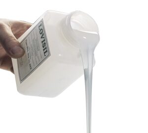
Instead of replacing the cable, the team opted for a smarter, more efficient approach: upgrade only the insulation system using the proven LoviSil liquid-silicone technology.
Thorne & Derrick are the UK’s specialist distributors for Lovink Enertech: LoviSil, PILC cable jointing solutions and MV termination systems; supporting utilities, DNOs, industrial sites and contractors with market-leading products.
Lovisil has been approved for use by NGED for more than 25 years and is also widely used by UKPN. It provides a dielectric strength greater than 21 kV/mm and remains fluid in service, allowing for natural movement without creating voids.
Lovisil has been been specified by National Grid Company Directive as a Standard Technique for Making 33kV Cable Terminations; download copy here.

National Grid Approved MV HV Cable Box Filled Compounds
Advantages of Lovisil v Resin & Compound Type Box Filling Compounds 11/33kV
- Cost-effective alternative to full switchgear replacement, enabling refurbishment and continued operation of existing assets.
- Supports asset life extension strategies by improving insulation performance and long-term reliability of ageing infrastructure.
- Minimum dielectric strength of 21 kV/mm, replicating and exceeding the performance of XLPE primary cable insulation.
- Fluid insulation technology continuously backfills any developing voids, eliminating trapped air pockets and reducing the risk of partial discharge.
- No air void formation during installation or service life, supporting long-term insulation reliability.
- The fluid medium allows natural cable core movement under thermal and load cycling without creating insulation gaps or stress points.
- More tolerant to harmonic loading and thermal cycling due to the absence of rigid insulation interfaces and void formation.
- Fluid insulation supports improved heat circulation and thermal dissipation around the conductors.
- Compatible with legacy cable materials and compounds, including G38 and bitumen-based systems.
- Simple single-part pour application with no mixing ratios, curing compounds, or complex preparation required.
- No requirement to grease or prepare the enclosure prior to installation, reducing installation time and contamination risk.
- Fast and straightforward installation process with minimal additional training or specialist skills required.
- Re-entry is simple and non-destructive — open and drain the fluid without cutting.
- No shelf-life limitations, removing concerns around expired materials or stock rotation.
- Ergonomically designed packaging developed specifically for field operatives, enabling controlled handling and pouring on site.
LoviSil Solution
Upgrading Without Replacing
1. Removing the Old Pitch/Bitumen/resin Medium
All degraded insulation compound was safely extracted by extensive time-consuming and careful cutting of the existing insulating medium from the termination box, exposing a clean cavity ready for refurbishment. Lovisil is directly compatible with traces or remnants of other compounds and resins so once most of the existing box-filling compound or resin has been removed the Lovisil can be used to re-fill the cable box.
2. Introducing LoviSil Liquid Silicone
The housing was refilled using LoviSil, a premium liquid-silicone medium designed for high-integrity insulation in MV applications up to 33kV.
Performance Advantages of LoviSil
Enhanced Insulation Performance
LoviSil delivers superior dielectric strength, helping reduce the likelihood of future failure.
Full Void-Free Insulation
The silicone compound flows into every internal space, eliminating air gaps that can lead to partial discharge (PD) and premature breakdown.
Compatible with Legacy PILC Installations
Because the system works seamlessly with the paper insulation of PILC cables, engineers avoided a costly and disruptive network decommissioning.
Long-Term Breakdown Resistance
LoviSil maintains integrity under thermal and electrical stress, offering a modern, robust alternative to historical insulation materials.

Why This Matters for Utilities & Network Operators
This project highlights an increasingly important theme in today’s power networks: extending the life of legacy infrastructure using modern materials and smarter engineering choices.
By retaining the original PILC cable and upgrading only the termination insulation, the client achieved:
-
Significant cost savings
-
Reduced downtime and site disruption
-
Improved long-term network reliability
-
A future-proofed termination assembly
Lovink
Reliable & Resilient Cable Jointing, Connection & Sealing Solutions for MV Networks
Cable Joints for Medium & High Voltage Cables | the Lovink range of waterproof cable joints provide high-performance for high-challenge applications including configurations for straight, transition, trifurcating-transition, branch and loop jointing of cables typically distributing electricity at 11kV, 24kV and 33kV; this includes connection joints for extensions and repairs for MV HV cables with XLPE, PILC & EPR insulation.
Lovink Enertech products are proven in service worldwide for network resilience, ease of installation, and long-term reliability.

Authorised Stockists & Distributors for Leading HV Cable Accessory Manufacturers
LV-HV Jointing, Termination, Substation & Electrical Eqpt Distributors 600V to 66kV
5 Cable Management Mistakes to Avoid – Improve Safety & Reduce Downtime
April 21st, 2026
5 Common Cable Management Mistakes And How To Avoid Them
Cable management is often overlooked but in industrial environments, it plays a critical role in safety, reliability and long-term performance.
Loose, poorly routed or unprotected cables can quickly become a hazard. From trip risks to equipment damage and unplanned downtime, small oversights in LV MV HV cable management can lead to larger operational issues.
In this Blog, we highlight five common cable management mistakes and how to avoid them.
That’s why choosing effective safety solutions like the CableSafe is essential for modern job sites.
Leaving Cables Unsecured
The Issue:
Unsecured cables are one of the most common problems across industrial sites. Whether temporary or permanent, loose cables create immediate safety and operational risks.
- Trip hazards for personnel
- Increased wear and abrasion
- Risk of snagging or disconnection
- Reduced cable lifespan
The Solution:
Use appropriate cable restraint systems such as cable cleats, supports or routing systems to keep cables secure and controlled throughout the installation.
Ignoring Dropped Object Risks
The Issue:
Cables installed at height can become a serious hazard if not properly secured. Movement, vibration or poor fixing can result in cables shifting or falling.
- Potential injury to personnel below
- Damage to surrounding equipment
- Unsafe access routes
The Solution:
Ensure all overhead cables are securely fixed using reliable systems. Consider cable retention as part of a wider dropped object prevention strategy, particularly in high-risk environments.

Poor Cable Routing
The Issue:
Poor routing can expose cables to unnecessary damage and create unsafe working conditions.
- Cables crossing walkways
- Contact with sharp edges
- Routing near moving equipment
- Cluttered or difficult-to-maintain layouts
The Solution:
Plan cable routes carefully to ensure they are protected, accessible and away from high-risk areas. Well-organised routing improves both safety and long-term maintainability.
Failing To Protect Cables From Damage
The Issue:
Cables exposed to harsh environments, foot traffic or heavy equipment are highly vulnerable to damage.
- Crushing or impact damage
- Environmental exposure
- Premature failure
- Increased downtime
The Solution:
Use cable protection systems such as guards, covers or cable bridges to shield cables from mechanical and environmental stress.
Relying On Temporary Fixes
The Issue:
Temporary fixes such as tying down cables or repositioning them manually may seem convenient but rarely provide consistent safety.
- Inconsistent protection
- Reliance on manual checks
- Higher long-term risk
The Solution:
Implement permanent cable management systems that provide consistent, reliable protection without relying on ongoing manual intervention.
Why Cable Management Matters
- Improves workplace safety
- Protects cables from damage
- Reduces downtime and maintenance
- Supports compliant installations
- Extends cable service life
In demanding industrial environments, even small improvements in cable management can have a significant impact on safety and performance.
Conclusion
Effective cable management is not just about organisation it is about protecting people, equipment and operations.
By addressing common issues such as unsecured cables, poor routing and lack of protection, businesses can create safer, more reliable installations that perform over the long term.
Need Support With Cable Management Solutions?
Thorne & Derrick supply cable cleats, cable protection systems and installation solutions for demanding industrial environments.
Speak to our team today.
