

Blog
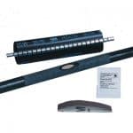
3M HDCW 140/40 Wraparound Heat Shrink Cable Repair
October 17th, 20183M HDCW 140/40
Contact us for price, delivery and technical support about 3M HDCW 140/40.
- Product Group: Heat Shrink
- Family: Wraparound Heat Shrink Cable Repair
- Manufacturer: 3M Electrical
- 3M Description: 3M HDCW Repair 140/40 – 250mm
- 3M Reference: HDCW 14/4-25
- Stock | Non-Stock: Stock – check with Thorne & Derrick

3M
3M Electrical Stockists Since 1985 ♦ Cold Shrink ♦ Scotchcast Resins ♦ Cable Joints ♦ Cable Terminations
♦ Scotch Electrical Tapes ♦ Heat Shrink ♦ LV MV HV Cable Accessories
THORNE & DERRICK
LV MV HV Cable Jointing, Earthing, Substation & Electrical Eqpt 11kV 33kV 66kV
3M HDCW 110/30 Wraparound Heat Shrink Cable Repair
October 17th, 20183M HDCW 110/30
Contact us for price, delivery and technical support about 3M HDCW 110/30.
- Product Group: Heat Shrink
- Family: Wraparound Heat Shrink Cable Repair
- Manufacturer: 3M Electrical
- 3M Description: 3M HDCW Repair 110/30 – 500mm
- 3M Reference: HDCW 11/3-5
- Stock | Non-Stock: Stock – check with Thorne & Derrick
3M
3M Electrical Stockists Since 1985 ♦ Cold Shrink ♦ Scotchcast Resins ♦ Cable Joints ♦ Cable Terminations
♦ Scotch Electrical Tapes ♦ Heat Shrink ♦ LV MV HV Cable Accessories
THORNE & DERRICK
LV MV HV Cable Jointing, Earthing, Substation & Electrical Eqpt 11kV 33kV 66kV
Feeder Pillars – Electric Vehicle (EV) Power Supply Pillars
October 17th, 2018
Feeder Pillars, Power Management & Control Equipment
-
Uploaded By - Chris Dodds (Thorne & Derrick Sales & Marketing Manager)
Guest Post By - Giles Davidson (Area Sales Manager at Lucy Zodion Limited)
Lucy Zodion were approached by the client (Eagle) to manufacture a galvanised steel feeder pillar from their Fortress range to supply three electric vehicle charging points within the clients own site – the double door feeder pillars are designed to provide robust and reliable distribution of low voltage electrical power.
The initial plan was for the EV charging points to be fitted to the wall of the building.
Lucy Zodion suggested that the side walls of the feeder pillar could be utilised to provide the three IP67 sockets, which lessened the upheaval to the site with less civil engineering, electrical and cabling work required.
The client also wanted to be able to provide electrical isolation via each socket from within the feeder pillar but also needed to ensure that only authorised personnel could do this.
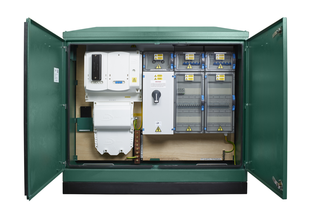
To achieve this Lucy Zodion fitted the new Hasp and Staple lock system so the client could fit a padlock as pictured below.
To complete the project the electric vehicle power pillars were painted to the clients specific RAL paint colour specification.
The design, procurement, assembly and testing was all completed in time and the customer saved money on the project.
Lucy Zodion bespoke feeder pillars with customised design and pre-wired solutions, tailored to the customers’ requirements without compromise.

Feeder Pillars – Electric Vehicle (EV) Power Supply Pillars

Feeder Pillars For Electric Vehicles With Padlockable Vandal Resistant Protection
Feeder Pillars
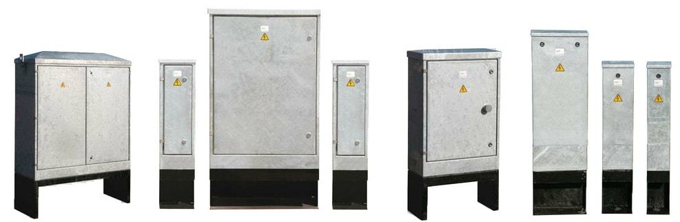
T&D together with Lucy Zodion are able to offer a range of feeder pillar enclosures and cabinets that are robust, durable and secure providing weatherproof and padlockable vandal resistant protection. Feeder pillars are available as standard empty enclosures or custom manufactured low voltage pre-wired electrical distribution equipment consisting of a robust galvanised steel pillar with vandal resistant lockable doors housing LV electrical switchgear and control systems.

EV Electricity Supply Pillar in production at Lucy Zodion incorporating CTCU and surge protection – the feeder pillar also uses Matt:e’s O-pen technology devices which eliminates the need for earth mats or rods.

Electric Vehicle Charging Supply Pillars – Lucy Zodion are empowering EV with pre-wired feeder pillar and electricity distribution solutions. Lucy Zodion develop EV solutions considering the charge speeds each charge point is capable of, from fast to super, to ensure the client receives the most suitable and compatible option. The standard range of pre-wired supply feeder pillars for EV charging come in four sizes and can supply power for up to 54 fast charge points, 12 rapid charge points and 2 super. Additional components can be integrated as optional extras, for smart and adaptive power distribution solutions.
Galvanised & Stainless Steel | Cast Iron | GRP | Pre-Wired | Underground Retractable |

Read our Blog with Lucy Zodion: Cut-Outs & Isolators – What’s the Difference?
THORNE & DERRICK SPECIALIST ELECTRICAL DISTRIBUTOR
LV ♦ MV ♦ HV
T&D distribute the most extensive range of LV, MV & HV Cable Jointing, Terminating, Pulling & Installation Equipment – we service UK and international clients working on underground cables, overhead lines, substations and electrical construction at LV, 11kV, 33kV and EHV transmission and distribution voltages.
- Key Products: MV-HV Cable Joints & Terminations, Cable Cleats, Duct Seals, Cable Transits, Underground Cable Protection, Cable Jointing Tools, Feeder Pillars, Cable Ducting, Earthing & Lightning Protection, Electrical Safety, Cable Glands, Arc Flash Clothing & Fusegear.
- Distributors for: 3M, ABB, Alroc, Band-It, Catu, Cembre, Centriforce, CMP, Elastimold, Ellis Patents, Emtelle, Furse, Lucy Zodion, Nexans Euromold, Pfisterer, Polypipe, Prysmian, Roxtec.

LV – Low Voltage Cable Joints, Glands, Cleats, Lugs & Accessories (1000 Volts)

MV HV – Medium & High Voltage Cable Joints, Terminations & Connectors (11kV 33kV EHV)

Cable Laying – Underground Cable Covers, Ducting, Seals & Cable Pulling Equipment
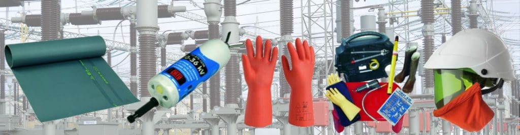
T&D, CATU Electrical Safety & Arc Flash Protection Specialists for SAP’s, Linesmen, Jointers & Electrical Engineers – Largest UK Stockist
3M HDCW 110/30 Wraparound Heat Shrink Cable Repair
October 17th, 20183M HDCW 110/30
Contact us for price, delivery and technical support about 3M HDCW 110/30.
- Product Group: Heat Shrink
- Family: Wraparound Heat Shrink Cable Repair
- Manufacturer: 3M Electrical
- 3M Description: 3M HDCW Repair 110/30 – 250mm
- 3M Reference: HDCW 11/3-25
- Stock | Non-Stock: Stock – check with Thorne & Derrick
3M HDCW 110/30 Cable Repair
3M Electrical Stockists Since 1985 ♦ Cold Shrink ♦ Scotchcast Resins ♦ Cable Joints ♦ Cable Terminations
♦ Scotch Electrical Tapes ♦ Heat Shrink ♦ LV MV HV Cable Accessories
THORNE & DERRICK
LV MV HV Cable Jointing, Earthing, Substation & Electrical Eqpt 11kV 33kV 66kV
How to Size High Voltage Earthing Conductors Correctly
October 15th, 2018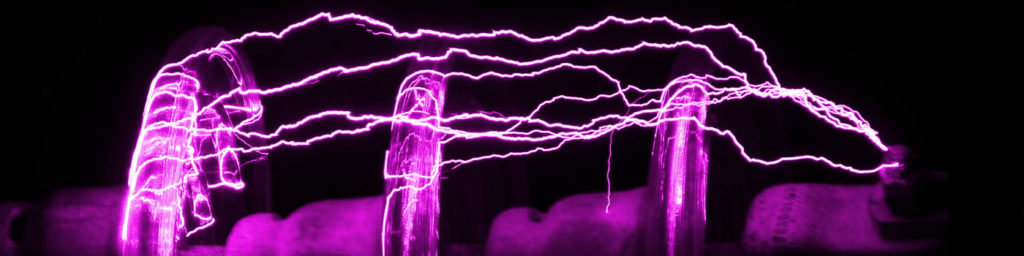
A Guide To High Voltage Earthing Conductors
-
Guest Blog by Ian Griffiths - Principal Partner at GreyMatters
What size earthing conductors should I use?
And, is there a simple table I can use for this high voltage earthing design?
These are great questions that I’m often asked. This post answers these questions together with the choice of conductor materials and jointing method within a high voltage earthing design project.
Assessing conductor size is entirely dependent on the electrical configuration and the load that the conductor must take. For example, an above-ground bonding conductor serves to transfer current with minimal voltage drop, from A to B.
A directly buried conductor has an additional purpose, that of leaking the fault current/voltage into the local geology (as part of an electrode).
When considering Lightning, the same conductor above might also see a high-frequency component and which will impose yet another requirement.
High Voltage Earthing Conductors
Design Considerations
In IEEE-std80ƒ Guide for Safety in AC Substation Grounding, section 11 – states the basic requirements are:
Each element of the grounding system, including grid conductors, connections, connecting leads, and all primary electrodes, should be so designed that for the expected design life of the installation, the element will
a) Have sufficient conductivity, so that it will not contribute substantially to local voltage differences.
b) Resist fusing and mechanical deterioration under the most adverse combination of a fault magnitude and duration.
c) Be mechanically reliable and rugged to a high degree.
d) Be able to maintain its function even when exposed to corrosion or physical abuse.
Earthing Materials
Copper has traditionally been the go-to material for years in high voltage earthing because it is not only highly conductive but also resistant to most sources of in-ground corrosion.
Similarly, aluminium has sufficient conductivity but suffers from in-ground corrosion, and the oxidation that forms around its surface is not conductive, therefore, compromises the conductor’s ability to leak current when buried, which is why buried aluminium conductors is a no-no.
Stainless steel or mild steel (when appropriately coated – galvanised or copper bonded), on the other hand, may not have the conductivity of copper or aluminium but it is sufficiently conductive to be utilised as a buried conductor.
Dealing with the Heat
So now we’ve covered the materials that are widely used for high voltage earthing.
Point ‘b’ from IEEE-std 80 above calls for the conductor to retain its mechanical strength when being exposed to a fault.
Conductors get hot when current flows through them. And they will potentially be at their hottest when subjected to a fault from the electrical system. This fault means the conductor needs to maintain its physical integrity as temperature increases and not transform into a shower of hot molten metal!
Up to this point, we’ve discussed conductor conductivities, materials and thermal-mechanical characteristics.
Another consideration for high voltage earthing is the method of the joint between conductors.
Conductor Joints
Joints in conductors are as critical to current-flow as the conductors themselves. The jointing method must not allow the joint to introduce excessive resistance. Therefore, the selection of the jointing method will impact the earthing system’s thermal resilience massively. This thermal resilience is why welded joints are the go-to choice for the high voltage earthing system.
Welded joints achieve the nearest physical match to the native conductor itself and are the gold-standard in conductor jointing because they accomplish a molecular similarity to the native material’s conductivity, as well as similar mechanical robustness.
Here’s an example of a safe method of igniting an exothermic weld.
A Word of Caution
Bolted joints and clamps are made up of multiple parts which can creep and loosen over time. Loosening will add resistance across conductor joints, which as previously mentioned… is not a good thing (thermal runaway is a topic for another day).
Bolted joints fall into the category of mechanical joint methods and have a derating factor to keep the conductors operating at lower temperatures. When designing a high voltage earthing system, this means the seemingly unrelated selection of jointing method will also impact the conductor size calculation.
IEEE adiabatic equation
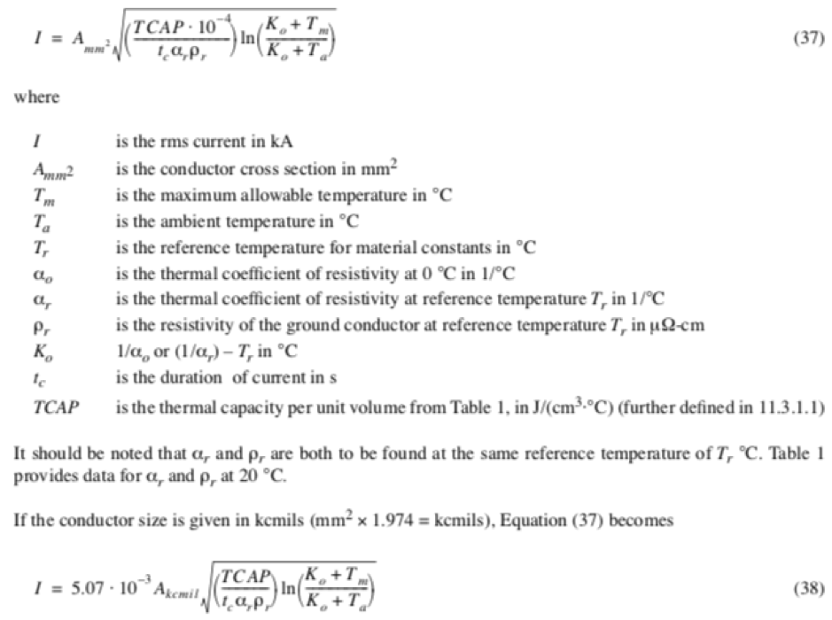
Calculating High Voltage Earthing Conductors
In Summary
So there you have it. Without going into great detail, the following factors influence conductor sizing:
- The magnitude and duration of fault current (i.e. the heat source)
- The method used for the joint
- The conductor material
- The conductor’s role in the high voltage earthing design
These factors may vary project by project, so, using a particular size of the conductor on a previous project does not mean that the same will apply to the next project, which means calculating conductor sizes (adiabatic equation) to fit the particular requirements of the project is usually very necessary.
ƒ IEEE P80 – Guide for Safety in AC Substation Grounding
This guide is primarily concerned with outdoor ac substations, either air-insulated or gas-insulated. With proper caution, the methods described herein are applicable to indoor portions of such substations, or to substations that are wholly indoors. No attempt is made to cover the grounding problems peculiar to dc substations. A quantitative analysis of the effects of lightning surges is also beyond the scope of this guide.
Further Reading
- High Voltage Earthing & Grounding System Design Protecting Lives
- Safer Exothermic Welding With Apliweld Remote Electronic Ignition
- Data Centre Earthing
Ian Griffiths CEng, MBA, BEng, MIET
Principal Engineer at GreyMatters, an Earthing & Lightning Protection Consultant of 27 years, one of the top 1% UKAS accredited CDEGS consultants and professional advisor to international utility companies, data centre and infrastructure developers. Risk Assessment Surveys and measurements for substation earthing or generation schemes on your electrical earthing system, voltages from 1kV to 765kV are undertaken by their highly qualified engineers.
Some LinkedIn Comments
Charles Shannon Senior Application Engineer at IMCORP
Hey Chris Dodds and Ian Griffiths – Substation Earthing. Great subject. I would add two minor clarifications to that blog. #1 when mentioning buried earthing conductors it’s worth clarifying that is for unjacketed cables. Additionally there in the maximum energy calculation note that with proper surge arresters this energy can be significantly reduced which can significantly reduce the size and thus the cost of the cable.
Ian Griffiths – Substation Earthing
Hi Charles, you might be right to add an additional clarification re buried conductors. Still, the piece is intentionally brief (so it’s not intended to be a definitive reference covering all the nuances), still, it does make the clear distinction between above-ground and below-ground conductors to try and get people to think about there being TWO differing purposes that an identical-sized conductor can have i.e. to either leak current (into the geology) or to transfer it (equipotn)… or a combination of both – Oh, that’s 3 but hey. So, for the sake of simplicity, it might be better to leave coatings for another blog 😉
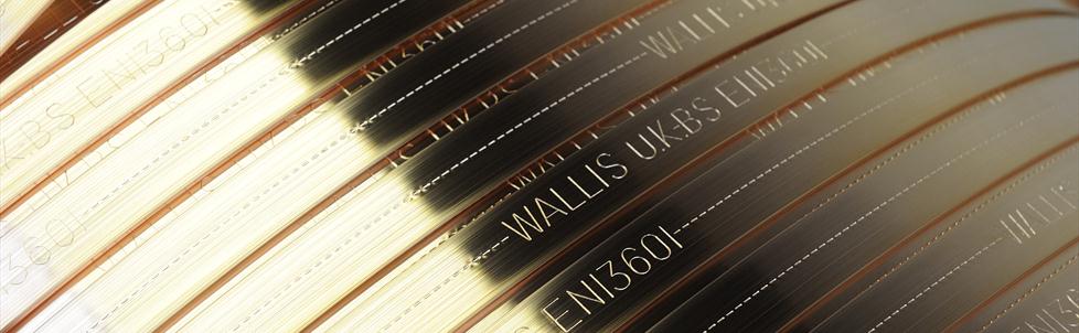
Earth Mats | Earth Plates | Earth Rods | Earth Bars | Earth Tapes | Exothermic Welding from T&D, The Earthing Equipment & Lightning Protection Eqpt. Distributors


