

Blog
GRP Cable Support Systems | Features & Benefits
November 23rd, 2022
GRP Cable Support Systems
Thorne & Derrick together with Mita® can offer an extensive range of GRP cable support solutions that are suitable for any kind of application. As a leading manufacturer of corrosion resistant industrial cable support products, Mita® hereby presents all you need to carry and support each and every kind of electric cable, data, instrumentation, computer or power circuit without any doubt.
Their GRP offer includes a complete industrial cable support systems and trough range specifically designed for harsh and corrosive environments. Whether you are specifying a range of equipment for a major project or buying a selection of components for a simple maintenance installation, their range is unequalled.
What is GRP?
GRP is a composite material formed if glass rovings/shavings together with resin fillers and additives. GRP is the abbreviation of Glass Reinforced Polymer, meaning it is a man-made resin based material which makes it a polymer, reinforced with glass. There are also different acronyms used by different manufacturers, such as FRP and GFRP, however, they all refer to the same type of composite.
The mechanical properties of GRP can vary widely depending on the matrix fibre combination, fillers, veils, reinforcement design, and manufacturing methods.
These properties allow an initial comparison of different types of composites as well as providing a benchmark against which to measure the success of the specific recycling process in achieving acceptable material properties.
How is GRP Manufactured?
GRP is manufactured through a process called pultrusion.
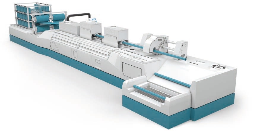
Above you see the glass rovings going into the resin bath, then mats are placed on to these to create the profile first and goes into the die which shapes and cures it in the form of a ladder or tray, and at the end of the line it is cut to the required length.
Pultruded Technology is used whenever the benefits of whole life cost are appreciated and although the process was originally developed in the USA around 50 years ago, low levels of technology have traditionally meant high costs and therefore applications suited mainly to the extreme longevity of the material.
Pultruded Composites consist of four or five main elements:
1) Glass rovings (strands) and mats -approx. 50% by weight
2) Resin – usually Polyester
3) Filler – usually Calcium Carbonate
4) UV Veil and UV additives
5) Fire Retardants as required
Pultruded composites remain largely impervious to corrosion regardless of application. The GRP pultrusion process uses a combination of unidirectional and cross strand glass mat which is resin impregnated and pulled through a hot die to produce a very solid, structurally sound profile.
Pultrusion process gives outstanding structural strength when compared to other composite processing techniques.
GRP Cable Support systems
Production Methods
There are 2 common production methods for GRP cable support systems, which are moulding and lamination (though pultrusion) and do not produce the same results.
Compression Moulding:
Light / Medium Duty
1.Enough structural strength for light and medium duty applications (Low/medium load carrying )
2.Glass content is around 20-25%
3.High filler content
4.Orthothalic resin or Isopthalic resin which might end up having a low fire retardancy
5.Good for indoor applications, its manufacturing results in nice bends and better shape
Lamination through Pultrusion:
Heavy duty
1.High structural strength for heavy duty applications (high load carrying)2.Glass content is around 40-55%
3.Low filler content
4.Isopthalic polyester resin which has a good corrosion/fire performance, and Acrylic resin resulting in better corrosion, fire performance and low smoke/fumes
5.Good for indoor and outdoor applications thanks to the UV surface veil applied during the lamination
The main 2 methods that we come across in GRP cable support manufacturing is pultrusion and moulded manufacturing.
Cable Trough Resin Types
MITA offers 4 main resin types to accommodate the requirements of various industrial applications which can be in chemically aggressive, demanding heated environments.
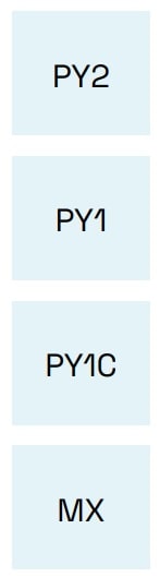 |
POLYESTER Type 2 | Referencing Convention: Ending with PY2 This type of polyester is for general applications, is resistant to corrosion suitable in industries using heavy chemical and caustic materials, and resistant to UV light by nature. |
| POLYESTER Type 1 | Referencing Convention: Ending with PY1 This type of polyester has better fire retardance which makes it suitable for railway, trackside and any other application requiring UL94 compliance and 5VA classification. |
|
| POLYESTER Type 1 Carbon Loaded | Referencing Convention: Ending with PY1C This type of polyester has anti-static properties as it contains carbon powder. It, therefore, requires grounding. It is for on-shore and off-shore oil and gas applications which are classified as explosive environment. |
|
| MODIFIED ACRYLIC | Referencing Convention: Ending with MX This type of polyester has anti-static properties as it contains carbon powder. It, therefore, requires grounding. It is for on-shore and off-shore oil and gas applications which are classified as explosive environment. |
Cable Trough Approvals
| Materials | Standards |
| PY2 | BS 476 Part 7 |
| BS EN 60695-2-12:2001 | |
| PY1 | UL 94 – V0 |
| UL 94 – 5VA | |
| BS EN 60695-2-12:2001 | |
| PY1C | BS476 Part 7 |
| UL94 – V0 | |
| UL94 – 5VA | |
| NES713 | |
| BS60079-0 | |
| BS EN 60695-2-12:2001 | |
| MX | BS 476 Part 7 |
| BS 476 Part 6 | |
| NES 713 | |
| BS 6853 – D8.3 | |
| BS 6853 –D8.4 Cat 1B | |
| BS 6853 – Annex B2 | |
| BS EN ISO 4589-2 | |
| BS EN iSO 4589-3 | |
| UL 94 V0 | |
| UL 94 5VA | |
| BS EN ISO 4589-2 | |
| BS EN ISO 4589-3 | |
| BS EN 60695-2-12:2001 |
| References | |
| Wibe full reference | Wibe quick reference |
| Polyester Class 2 | PY2 |
| Polyester Class 1 | PY1 |
| Polyester Class 1 Anti Static | PY1C |
| Acrylic Class 0+ | MX |
GRP Cable Support Solutions
Features & Benefits
| Features | Benefits |
| Light weight Density and weight are significantly lower than steel (70% lighter than steel) with reduced handling requirements. Lightweight in design. |
Health & safety Reduced risk of staff injuries due to its lightweight, easy to cut, no hot works requirement, no deburring and no sharp edges. |
| Compression strength Despite its lower weight, tension, flexure and compression strength of GRP is almost 20 times that of steel with much greater safety factors. It does not deform permanently under high loads. Slow heat transfer allows for even stronger mechanical resistance. |
Low installation & transport costs Typically between 30-40% less than steels with easier cutting, drilling and no deburring, painting or earthing. Transportation costs are more economical and the ease of installation ensures that GRP is the more cost effective solution. |
| Slow heat transfer & resistant to electromagnetic pulses It is effective at temperatures between -140oC to +120oC. Resistant to electromagnetic pulses and transfers heat more slowly than steel. Composite materials are excellent insulators having a thermal conductivity 1/60 of a steel product, and do not require earthing. |
Long life & low maintenance Composites are corrosion resistant and maintenance free. Our GRP products are designed and manufactured to withstand a majority of chemicals & extreme weather – without requiring further maintenance. No rusting, even when exposed to salt spray, H25, acid build up from exhaust gases or brake dust. |
| Zero halogen, UV & corrosion resistance GRP cable support solution is resistant to UV and corrosion, and is zero halogen. It is also available in low smoke classified material. |
Fire performance GRP is zero halogen. It has low heat and electrical conductivity, and is available in self extinguishing and low smoke material. |
| Offer & design Available in 3m and 6m lengths. Full range of pre-manufactured bends, jointing bays and transitions available for fast installation. Dedicated design facility to support bespoke solutions. |
Installations & modifications are simpler Mita GRP solutions offer a far easier installation, without the need for painting, earth bonding or special tools. Supplying 6m or 3m lengths reduces amount of couplers required. |
MITA, Schneider Electric + Wibe Group
In 1988, Mita Holdings Ltd was born. In a short while, the company became a leading manufacturer of corrosion resistant industrial cable support products in the UK. In 2005, the company was acquired by Schneider Electric under the name of Mita (UK) Ltd. Mita name continued as a range name under the Schneider Electric brand. Finally, in 2021 the cable support division is acquired by the Swedish group, Storskogen, and is reborn as a stand alone company, Wibe Group.
MitaR is back as a leading brand in GRP cable support solutions. MITA brand is now powered by Wibe Group.
MITA have been supporting customers through their technical journey on choosing the correct product, manufactured from GRP, in cable support applications for almost five decades. MITA are now fully separated operationally from Schneider Electric. They now have a stand alone presence in the UK market with their “Made in UK” products which are fully compliant to the related cable management standards.
MITA are marker-leaders in the manufacture of GRP non-metallic troughing, GRP cable ladders, CABSYS cable trays, ducts, cable support channels and Fibastrut as the brand continues to lead the industry towards a sustainable future for a wide range of low (LV), medium (MV) and high voltage (HV) cable installation applications.
RAIL CABLE ACCESSORIES, ELECTRIFICATION

& INSTALLATION EQUIPMENT
Thorne & Derrick supply an extensive range of 400V-33kV Rail Cable Accessories & Power Distribution Systems including feeder pillars to contractors undertaking Low Voltage Power Distribution, HV Electrification & Substations, DC Traction & Networks, OLE and Track Feeder Cable Renewals – a complete range of Network Rail PADS approved track terminations, cable joints, cable repair and connection products up to 25kV, including 3M Cold Shrink, Pfisterer CONNEX and Nexans Euromold products.
Full range of Cable Pulling Equipment & Products to ensure safe and efficient of rail cables in to cable ducts and containment infrastructure including cable troughs.

Cable Cleats | Cable Hangers | Cable Joints | Cable Glands | Cable Lugs | Cable Transits | Arc Flash Clothing
Earthing System Testing | Are We Really Testing R, Z or Something Else?
November 15th, 2022
Earthing System Testing
-
Special thanks to Stephen Palmer from Safearth for kind permission to republish this article
In theory, earthing system testing is very simple, but in practice somewhat more complicated. Recently our development engineers Matthew Lee and Steven Preedy asked the question…Are we really testing R, Z or something else?
The authors have investigated and tested a range of scenarios and instruments and sought to be definitive. This article presents their methods, results, and conclusions.
In theory, earthing system testing is very simple. One simply applies a voltage between the system under test and a remote earth electrode, measure the current, measure the voltage ‘across’ the system under test, and divide it by the current.
In practice earthing system testing is somewhat more complicated. Questions often arise regarding the practicalities of testing, including:
- How do you establish a suitable remote earth?
- What type of voltage do you apply?
- How much current flow do you need?
- Where & how specifically do you measure the voltage?
- How do you measure both reliably?
- How do you detect and reject (or correct for) electrical noise, both AC & DC?
These are all important questions, and whilst many have reasonable answers, one question remains in dispute: If you test with an applied voltage that has both DC & AC characteristics, do you measure a resistance or an impedance?
The IEEE committee revising Std 81, amongst others, have wrestled with this question, and currently, there is no consensus. To answer the question “Are we really testing R, Z or something else?” the authors have investigated and tested a range of scenarios and instruments and sought to be definitive. This article presents their methods, results, and conclusions.
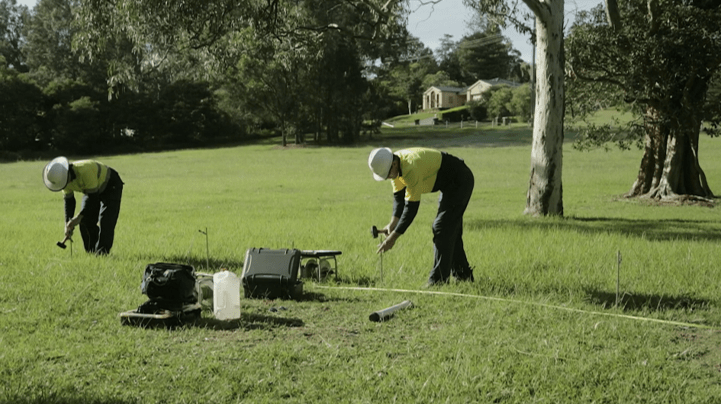
Safearth consultants in the field performing soil resistivity testing
Why are we asking this question and what are we testing?
For an earthing system to be effective, its performance needs to be adequate for the power system attached to it and all the factors that affect its performance need to be considered. The performance of the earthing system is entirely dependent of the ground in which it is placed.
The soil composition, existing infrastructure and mineral/moisture content all affect the apparent resistivity of the soil and thereby the performance of the earthing system. To assess the performance of an earthing system requires tests of parameters associated with or affecting that performance, including soil resistivity, EPR, resistance of earth grid, loop impedance, and continuity.
How Are We Testing?
To measure each of the aforementioned parameters current must be injected into the earthing system and/or the surrounding soil and the response measured. The injected current can be either a ‘Switched DC’ or an ‘AC current’ injection.
In both methods, the current is known, and voltage is measured. The question we are investigating here is “for a switched DC injection how should the measured voltage be interpreted?”
How do switched DC instruments work?
Switched DC instruments inject a known current in the form of a switched current square wave into the system. The voltage measurement is conducted at a specific part of the injected waveform, some in the middle and some at the end of the waveform.
Measurements are taken at these points to remove the effect of test lead coupling. With a known current and a measured voltage, ohms law can be applied – (R=V/I) to deduce the measured resistance.
What Happens When It Gets Complex?
Reactive elements in the system introduce complexity to an earthing system’s response. When measuring a complex system, the presence of reactive elements can affect the measured result. These reactive elements come from auxiliary paths such as overhead earth wires, buried conductors and cable screens.
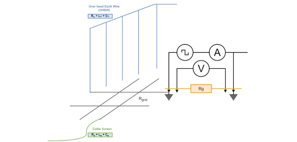
Figure 1 Resistance Measurement of Complex Earthing System
How we showed the measurement can include errors
Using two switched DC instruments, we set up an equivalent circuit that would allow us to change real and reactive components. From this we could simulate how the measurement waveforms become distorted as the ratio of L to R increases and what the resistance tester records as the apparent resistance.
The setup was measured with zero inductance initially to establish a control value. All other measurements with inductance were compared to the control value.
What happens when we have reactive elements?
Based on one theory the behaviour of reactive elements is just …

The reality is that high inductance reacts to the injected switched DC current such that the resulting voltage waveforms become distorted, as shown in Fig 3. The distortion in the measured voltage waveforms create error within the measured resistance.
The result is that the magnitude of the measurement is larger than the resistive component of the circuit and is not indicative of the system under test. If the reactive element is small in relation to the real resistance, there exists a plateau near the falling edge of the received signal. This plateau is the real magnitude and contains little to no error being uninfluenced by the reactive element. By using the plateau of the signal, the measurement can be effectively used to calculate the real resistive element.
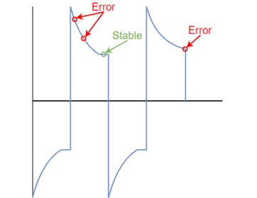
Figure 3 Measured voltage waveforms in high inductance circuits
How does impedance affect the results?
What we found was that the effects of inductance on measurement accuracy and reliability are dependent on the ratio of R to L, with the following features:
- Large R values negate low L values;
- Large L values dominate low R values;
- The L/R ratio does not imply the associated error;
- The error becomes significant when the millihenry range of inductance is reached; and
- The lower the frequency the more time for reactive elements to dissipate, allowing more time for a plateau to be reached.
Are we measuring an impedance with switched DC?
The short answer is no. Switched DC current injection measures the voltage at a certain point of the waveform and applies Ohm’s Law (R=V/I). It cannot measure a phase angle and thus cannot get a phase shift to deduce impedance.
The long answer is, it’s complicated. Due to the truncated measurement window technique used specifically by these testers, quantifying the amount of reactive information captured in that sample window is not trivial. In addition to this, the result is not a linear increase in error for a linear increase in inductance.
Does It Matter?
Typically, switched DC measuring instruments are reliable for individual electrodes, groups of electrodes and small to medium sized grids with no or minimal interconnecting paths. When testing on large grids or grids with multiple auxiliary paths, the effect of reactive elements can be observed by changing the injected frequency and noting that the recorded resistance changes with frequency.
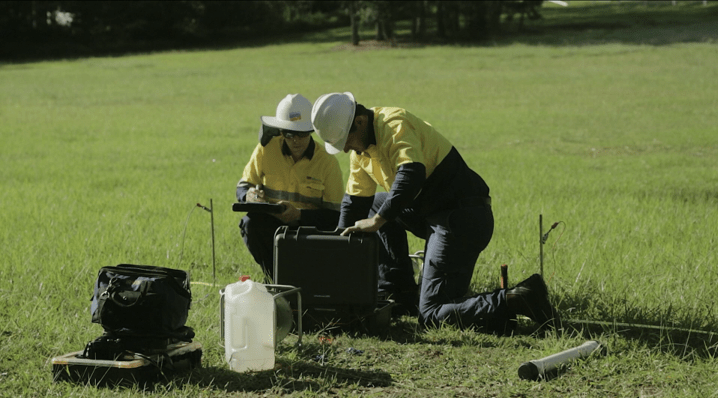
Safearth engineers in the field performing soil resistivity testing
We ask again…. Are we really testing R, Z or something else?
These instruments are suitable for testing a resistance until they cross an implicit R/L ratio threshold. Past this threshold it appears that the inductive (L) component affects the measurement sufficiently such that substantial error can be observed. This measurement is relative to the circuit under test, but the reactive element cannot be deduced.
Through this investigation, it was found that 3 & 4 terminal switched-DC testers are always attempting to measure a resistance. When significant reactive elements are introduced into the circuit under test, the instrument ends up reading something else as it is trying to calculate resistance despite the measured waveform being distorted by the presence of the reactive elements. This implies that it is not an impedance being measured, the value that is calculated is only relevant to that specific circuit.
A way to check if there are reactive elements in the circuit is to change the frequency of the square wave. If the value doesn’t change, then it is dominantly resistive, and the measured estimate is valid. However, if the measured value changes significantly, there is enough of a reactive element in the circuit under test to affect the result and it must be considered an invalid measurement.
This article comes from the perspective of Safearth development engineers Matthew Lee and Steven Preedy who research, design, develop and manufacture our suite of Safearth earthing system test instruments. Their consultants regularly use our earthing testing equipment in the field in Australia and overseas. Original article can be found here – https://www.safearth.com/are-we-really-testing-r-z-or-something-else/
About Safearth

Safearth is a specialist electrical engineering group providing world-recognised expertise in safe power earthing systems.
Safearth delivers comprehensive earthing solutions and management to safeguard people and infrastructure from electrical faults and lightning. Since being established more than 30 years ago, we’ve designed and tested thousands of earthing systems for high voltage installations, for power utilities, mines, oil & gas sites, and other industries.

THORNE & DERRICK are national distributors of LV, MV & HV Cable Installation, Jointing, Duct Sealing, Substation & Electrical Equipment – we service UK and global businesses involved in cable installations, cable jointing, substation earthing, overhead line and electrical construction at LV, 11kV, 33kV and EHV.
Since 1985, T&D have established an international reputation based on SERVICE | INTEGRITY | TRUST.
Contact us for 3M Electrical, ABB, Alroc, AN Wallis, CATU Electrical, Cembre, Centriforce, CMP, CSD, Elastimold, Ellis Patents, Emtelle, Euromold, Filoform , Furse, Lucy Electric & Zodion, Nexans, Pfisterer, Polypipe, Prysmian, Roxtec, Sicame, WT Henley.
3M Dynatel | 1420 Marker Locators for Underground Cables & Utilities
November 15th, 2022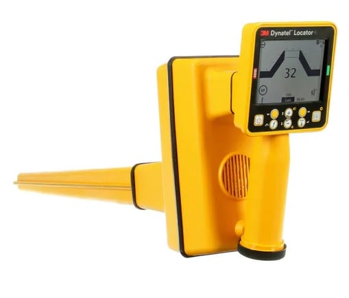
3M Dynatel Electronic Marker System Locator 1420X/XE
3M Dynatel
1420 Marker Locators for Underground Cables & Utilities
3M Dynatel Locators 1420X/XE Series determines exact location of underground 3M Electronic Marking System (EMS) Markers. There are two variations of the locators 1420-iD and 1420E-iD.
3M Dynatel Locators are microprocessor-based systems that incorporate advanced digital signal processing techniques to quickly and efficiently locate underground cables and utilities even years after construction or maintenance.
This locator reads, writes and locates 3M™ iD Markers.
It locates 2 different marker frequencies simultaneously. It features a lightweight design, large display with easy-to use interface, enhanced connectivity, internal GPS module, and includes Li-Ion battery with built-in charger.

Electronic Marker System Marker Locator | 3M Dynatel
Designed to be accurate, fast and integrated allowing you to accurately and easily:
- Locate, read and write to 3M iD markers
- Pinpoint the depth and location of all existing models of properly installed underground passive EMS markers
- Conduct direct depth reading of markers
- Locate two different marker frequencies simultaneously
Advanced Features
Detect Information About Underground Utilities
A feature exclusive to the 3M 1420-iD/1420E-iD locators is the ability to read, write and lock programmed information into the 3M™ Electronic Marker System iD Markers.
Information such as a pre-programmed unique identification number, facility data, owner information, application type placement date and other details from up to 100 markers can all be stored with date/time stamp and transmitted back to your PC for enhanced resource management.
Accurate Even In Congested Areas
The 3M 1420-iD/1420E-iD locators are unaffected by metal conduit or pipe, metallic conductors, fences, AC power or electronic markers for other utilities. Multiple markers located at close proximity can be read individually using this system.
A Simple, Easy-to-use System
Lightweight and compact, the locators are rugged, ergonomic and require very little operator training. A large bright backlit digital liquid crystal display screen and soft-key operation make them easy to understand and use for more precise locates.
A “memory” feature remembers operator set-up from the previous use. A standard RS232/USB communications port allows interface to an external computer for uploading/downloading of data, unit configuration and remote software upgrades. The system is estimated to operate for more than 25 hours on eight AA alkaline batteries.
Exclusive GPS System Adds Accuracy With Ease
The 3M™ Dynatel™ Electronic Marker System Marker Locators 3M 1420-iD/1420E-iD are now compatible with select GPS/GIS field mapping instruments for real-time mapping of marker placement.
The customized Dynatel interface commands the GPS/GIS device allowing even a generalist field technician to perform real-time mapping. It’s a simple system for mapping marker placement and saving information directly into CAD and GIS systems.
The electronic export of this information in GIS format creates an automated paperless system for records updating, making positive locates in the field easier than ever.
Additional Features Include
- Large backlit, high-resolution graphic display
- PC interface via standard RS232/USB
- User-configurable features and interface
- Detects all seven EMS marker frequencies
- Locator PC tools software
- iD marker read/write capability
- Dual marker frequency search-simultaneous
- iD Marker depth estimation
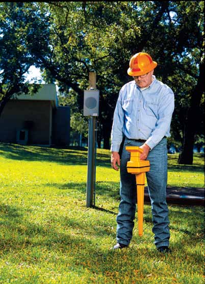
3M Dynatel Technical Specifications
| Physical Specifications | ||
| Size (H x W x D) CM (in.) | Weight (including batteries) | |
| Receiver | 26,7 x 11,8 x 76,2 (10.25 x 4.7 x 30) |
1,9 kg (4 lb.) |
| Shipping | N/A | 5,3 kg (11.5 lb.) |
| Environmental Specifications | ||
| Operating temperature | -20° C to 50° C (-4° F to 122° F) | |
| Storage temperature | -20° C to 70° C (-4° F to 158° F) | |
| Regulatory | CE (Export Models Only) | |
| Standard | IP54 | |
| Electrical Specifications | ||
| Marker compatibility | All 3M markers (telephone, gas, communication, power, water, wastewater and general purpose) | |
| Dual marker mode | Any two marker frequencies simultaneously | |
| Detection range | Exceeds maximum marker depth specifications | |
| Marker read range | 1420 Near Surface 3 ft. (.9 m) Ball 5 ft. (1,5 m) Full Range 8 ft. (2.4 m) |
1420E Near Surface 0.6 m (2 ft.) Ball 1,2 m (4 ft.) telephone, gas, CATV, wastewater 1,0 m (3.3 ft) water, power Full Range 2 m (6 ft.) |
| Marker write range | 30 cm (1 ft.) | |
| RFiD Marker depth measurement accuracy | +/- 10% +/- 5 cm (2 in.) up to marker depth specifications | |
| Memory storage with date/time stamp | Read marker records 100 Written marker records 100 User defined iD templates 32 |
|
| Marker depth memory storage | Five with date/time stamp | |
| Power | Battery type: eight AA size, alkaline Typical battery life: 25 hours |
|
| Display | Large graphic high-contrast LCD with backlight | |
| Speaker | 0.25W | |
| Headphone jack | Standard mini-jack | |
| Serial port | Standard RS232 serial with DB9 connector (USB adapter cable included) | |
3M Dynatel 1420-iD
Keypad & Display Definitions
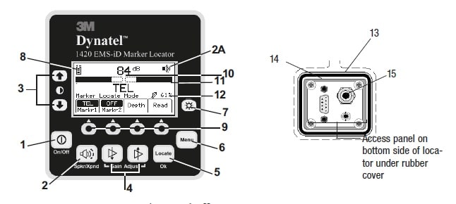
[1] On/Off (Power): Turns unit on and off.
[2] Speaker Volume Control: [2] Adjusts the volume of the locator (off, low, medium, and high).
[2A] Speaker Volume Icon: Indicates the relative volume level of the locator.
[3] Contrast: The arrows located above and below the contrast icon will adjust the contrast of the display.
[4] Gain Adjust: Adjusts the sensitivity of the locator either up or down to maintain a satisfactory signal level.
[5] Locate/OK: Sets the locator to trace mode for locating markers. Also acknowledges setup entries (OK).
[6] Menu: Displays setup screen for configuration of the unit, i.e.: clock, language, depth units, and marker data.
[7] Backlight: Toggles the backlight low, high, and off.
[8] Battery Icon: Indicates battery level.
[SK] Soft Keys: There are four soft keys (yellow keys) on the locator. The function of each key is shown above the key on the display screen. The functions will change, depending on the operation mode of the locator. For instruction purposes in this manual, the display command is followed by [SK] to identify it as a soft key.
[9] Soft Key Commands: Definitions for each of the four soft key functions.
[10] Signal Strength: Digital reading of the signal strength that the locator is detecting from the marker.
[11] Bar Graph: Graphical representation of the received signal.
[12] Gain Level: Displays relative gain level.
[13] External Jack: Not active on this model.
[l4] Serial Port: RS232 port to connect the locator to a PC via serial cable or USB-to-Serial Adapter cable.
[15] Earphone Jack: Will fit standard 1/8 inch (3.175 mm) mini-jack mono earphone plug (not included).
Ordering Information from 3M Electrical
| 3M Electrical Part Number | Description |
| 3M 1420 | EMS-iD marker locator with iD read/write |
| 3M 1420E | EMS-iD marker locator with iD read/write (CE Approved Export Model) |

Since 1985, Thorne & Derrick have been Approved Distributors for 3M Electrical Products (LV HV) including Cold Shrink and Scotchcast products – whilst the competitive supply of product from stock on short lead times is essential to the distributor it is equally vital that 3M product reputation is preserved through the correct installation of products in accordance with 3M recommendations.
BASEC Medium Voltage Approval Scheme & The Importance Of Surveillance Testing To Protect The Cable Industry
November 1st, 2022
Medium Voltage Cables Approval Scheme
BASEC are collaborating on knowledge and content sharing with Thorne & Derrick.
T&D have been Specialist Distributors of Medium Voltage Cable Accessories since 1985 and understand the criticality of specifying and supplying Type Tested products to international standards to ensure the safety, reliability and longevity of MV power systems.
The meteoric rise in demand for digitalisation coupled to the Green Energy revolution has further fuelled industry need for MV power – if electrical power is the lifeblood of a data centre or a wind farm then cables are the main arteries.
T&D together with BASEC have a shared passion and objective to enhance electrical safety through the education and encouragement of industry stakeholders to specify and buy accredited, tested and certified MV Cables & Cable Accessories, whatever the industry.
Medium Voltage (MV) cables are used in critical applications where major failures and injuries may occur. Regulatory bodies and governments’ specific safety requirements and compliance are vital in eliminating safety-critical system failure. Product quality is usually measured through the material tests of products.
Manufacturers must conduct tests following methods specified within international or industry standards to demonstrate compliance with their materials.
Understanding material properties enables manufacturers to use materials suitable for specific end-user applications. Maintaining the quality and reliability of the finished products is also essential.
BASEC certification includes mandatory annual material testing of cable compounds. This way, a BASEC certified manufacturer can demonstrate that the same compound formula has been used. If the manufacturer changes the materials, BASEC can pick this up in surveillance testing. For the continuity of quality, routine surveillance is needed regularly to check whether the materials used are identical or not.
As technology develops and continuous innovations in material knowledge take shape, the manufacturer may need to maintain alternative formulas and suppliers for their cable design. Additionally, global material shortage reinforces this requirement.
BASEC can list those suppliers and formulas under BASEC certificates to support manufacturers and provide peace of mind to end-users. With continuous surveillance testing and audits twice a year combined with an unannounced visit to the manufacturer at random and take samples for testing.
BASEC Medium Voltage Approval Scheme
BASEC MV Surveillance Scheme vs Non BASEC Scheme
With an increased demand for energy, medium voltage networks need to provide constant power for industries and end-users. To ensure reliable network operation, continuously maintaining quality MV and HV cable products is essential.
The market typically has been primarily a singular test report, in other words, an initial Type Test or Factory Acceptance Test (FAT) at the manufacturer. It is not uncommon to encounter 5 year and older Type Test reports demonstrating their compliance onsite.
Technological developments and economic reasons each year pressure manufacturers to seek alternative designs and suppliers. The old Type Test report only demonstrates the compliance of MV cable for that single batch which is not a good indicator for today’s energy network and end-user. Although the FAT test is performed in each batch on request by the client/purchasers, it is not done in a controlled environment.
The accuracy of the test results can be questionable. The cables must be validated by an independent third party and accredited body like BASEC.
For high quality and continuous operation, BASEC provides MV cable approval to comply with local and international standards and meet end-user specifications. This protects the end-user from failure and extra maintenance costs. BASEC approved cable tests are carried out regularly – mechanical, electrical, construction and material Testing take place annually and are used in projects to operate safely for extended periods.
By certifying cables with BASEC, cables are subject to rigorous recurring tests and audits.
Thanks to these annual surveillances and testing cables direct from the market, end-users and contractors ensure their systems’ reliability by specifying BASEC approved cables in their projects.
By doing the above surveillance, BASEC can certify a range of cables as specified in the standards, saving costs when getting the approval instead of testing each cable individually. Providing the cables pass the initial type tests and are under surveillance schemes such as BASEC approval.
The importance of accredited lab testing vs manufacturer own type tests and what this means to the market and users for safety
By accredited to ISO/IEC 17025 through an independent, impartial accreditation body, laboratories demonstrate their technical competency, laboratory quality, performance, reliability, and efficiency to ensure the accuracy of the test results. There is always the risk that unaccredited test laboratories can produce different test results.
This can be a result of equipment use, environmental factors, staff competency, and uncalibrated and unmaintained types of equipment. To avoid these different results and to ensure the test’s accuracy, ISO/IEC 17025 accreditation must be followed by labs as a regulating reference.
As mentioned above, in-house generated manufacturer test reports are more prone to uncertain human and equipment errors. BASEC’s ongoing surveillance scheme continuously checks the cables’ conformity to ensure the quality has not dropped from the first set of initial Type Testing. This gives the manufacturer product approval for a cable; before they can mark it with the BASEC Quality Mark. When placed on the market, this then gives purchasers confidence in the ongoing quality and conformity of the product.
BASEC has an independent cable laboratory accredited by UKAS against ISO/IEC 17065 for Product Certification, against ISO/IEC 17025 for Testing, and ISO/IEC 17021-1 for Quality Management Systems Certification and Environmental Management Systems Certification.
BASEC labs are recognized under the European Accreditation Multilateral Agreement (EA MLF), the International Laboratory Accreditation Cooperation (ILAC), and the International Accreditation Forum (IAF), as well as being UKAS Accredited.
Testing your cables at BASEC accredited labs provides you with validated test results globally. Cables tested and approved by BASEC accredited to ISO/IEC 17025 are placed on the market and can be specified in projects confidently.
To read the original article please click here – https://www.basec.org.uk/news/2022/9/7/basec-medium-voltage-surveillance-scheme-vs-non-basec-scheme-the-importance-of-cable-material-testing/
About Basec

BASEC is a global leader in cable testing and certification services for power, energy, data/signal cables and ancillary products, alongside quality management systems.
Operating independently for over 45 years, the BASEC mark is trusted for quality, clarity and impartiality.
BASEC’s teams of highly skilled engineers, technicians and auditors possess extensive in-depth commercial, industrial and technical experience. As a result, BASEC has a reputation for professional and rigorous assessment processes which ultimately lead to the issuing of our highly respected product certifications and test reports.
In addition, BASEC offers a number of supporting services for cable makers, traders and users, including management system certification, bespoke type testing, impartial investigation of conformity issues and testing and reporting in the event of disputes. Furthermore, Certificates of Assessed Design are available for innovative cable products.

Thorne & Derrick are national distributors of LV, MV & HV Cable Installation, Jointing, Substation & Electrical Equipment – this includes 3M Cold Shrink, Nexans Euromold and Pfisterer CONNEX Cable Accessories for Medium Voltage Power Systems.
We service businesses involved in cabling, jointing, substation, earthing, overhead line and electrical construction at LV, 11kV, 33kV, 66kV and EHV. Supplying a complete range of power cable accessories to support the installation and maintenance of low/medium and high voltage voltage power systems:
- Slip-on Cable Terminations
- Cold-shrink Cable Terminations
- Heat-shrink Cable Terminations
- Cable Joints – Heat & Cold-shrink
- Separable Connectors (Euromold)
- Surge Arresters & Switchgear/Transformer Bushings
Key Product Categories: Duct Seals | Cable Cleats | Cable Glands | Electrical Safety | Arc Flash Protection | Cable Jointing Tools | Cable Pulling | Earthing | Feeder Pillars | Cable Joints LV | Joints & Terminations MV HV

JTS by Nexans | A modern generation of MV Cable Joints have been developed by Nexans for the UK utility and contracting industry – the primary application of JTS Joints is for the jointing of 11kV 24kV and medium voltage power cables up to 33kV/42kV.
September 2022 VOLTS!
October 27th, 2022
THORNE & DERRICK LV HV Jointing, Earthing, Substation & Electrical Eqpt
Welcome to our initial industry bulletin – VOLTS.
So what is VOLTS?
VOLTS is our first monthly round-up of industry news, projects, videos, technical tips, training information, promotions, webinars and career opportunities from Thorne & Derrick. Take a moment to Follow Us on LinkedIn to receive future VOLTS.
In The News
Net Zero Teesside
Net Zero Teesside Power (NZT Power) will be the world’s first commercial scale gas-fired power station with carbon capture, and the hub of a decarbonised group of industries on Teesside who will share the CO2 transportation and storage infrastructure being developed by the Northern Endurance Partnership to serve the East Coast Cluster.
Net Zero Teesside Power’s proposed combined cycle gas turbine electricity generating station will have an electrical output of up to 860 megawatts (MW) of low carbon electricity, enough to power up to 1.3m homes per year.
From the power plant alone, the proposed carbon transportation and storage infrastructure will capture and store up to two million tonnes of CO2 a year.
These proposals help support the UK government’s commitment to fully decarbonize the power system in the UK by 2035 and will help to enable greater deployment of renewable energy such as wind and solar by providing flexible, dispatchable low carbon electricity generation which backs up intermittent renewables – crucial for periods when the wind isn’t blowing, and the sun isn’t shining.
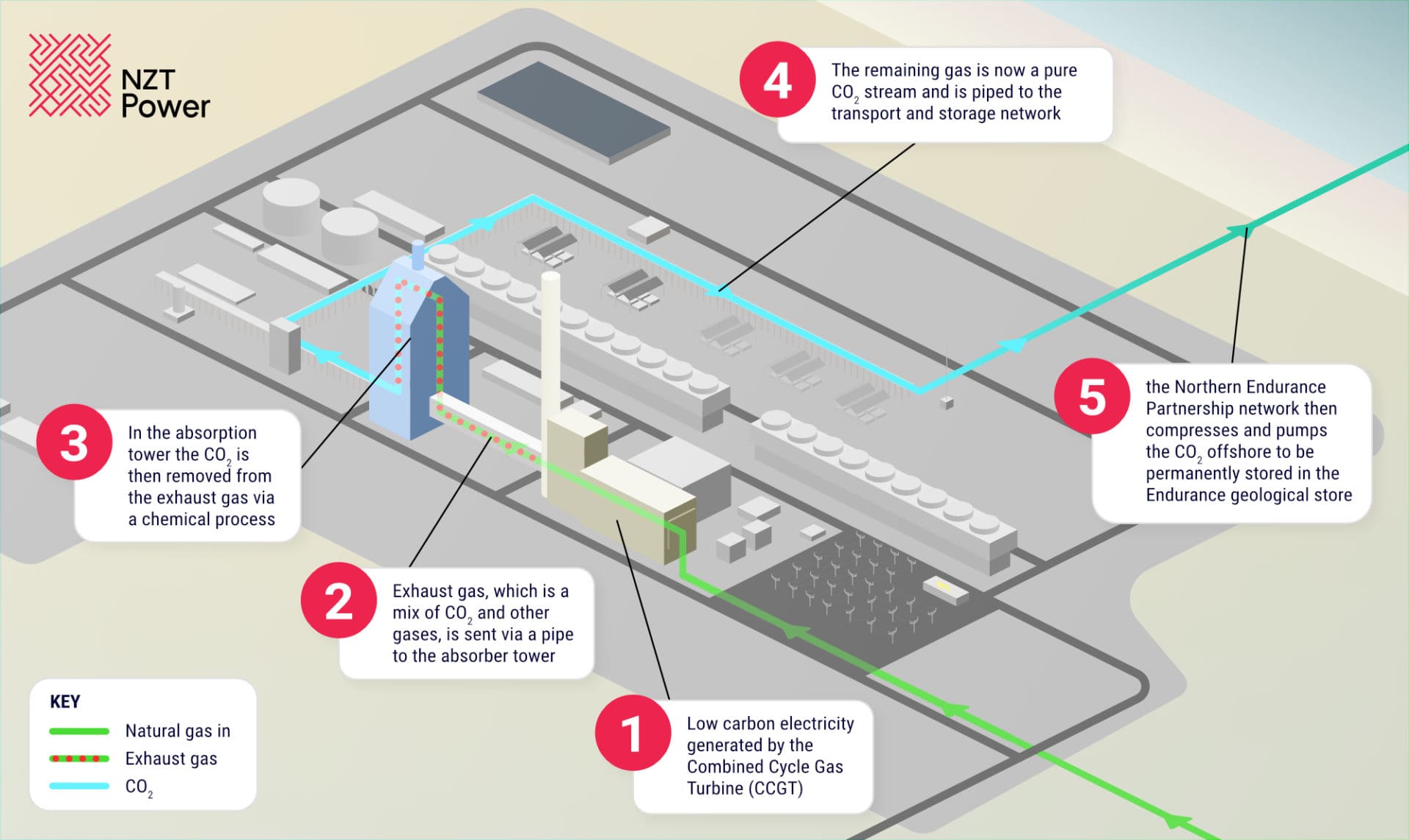
In January 2022, an exciting partnership was agreed with NOF, a regional business development specialist for the energy sector, to support supply chain engagement.
A Record Sales Year!
In this record sales year for Thorne & Derrick we have now signed Strategic Supplier Frameworks for MV/HV Cable Accessories & Tooling with 4 multinational power companies whom provide the global drive and expertise to continue the path to a sustainable Green energy future.
This week we have achieved Approved Supplier Status to Nordex Group and are now delivering a 33KV Cable Accessory & Electrical Safety package to their Oweninny Wind Farm.
As a leading supplier to the electrical sectors of diverse industries, we support customers by providing specification and Jointer Training Services plus competitive product supply from extensive stocks to UK, EU and International projects.

pROJECTS & NEWS
T&D Deliver Essential Equipment With Same Day Turn Around
Thorne & Derrick are profficient in the supply of solutions that are best suited to the intended application, including the fast replacement of incorrect equipment where necessary, to ensure that clients are able to complete required jobs on time.
This month we organised same day delivery for some SPS outdoor terminations and 2 hole 630sqmm Cembre lugs to replace equipment that was not appropriate for the client’s application. The client previously ordered indoor terminations and single hole cable lugs which were incorrect for the job at hand. The fast delivery of equipment to the client enabled the workers on site to continue with work as normal without delay.

Cable Joints & Terminations
Thorne & Derrick distribute the most extensive range of MV HV Medium & High Voltage Cable Joints, Terminations & Connectors from manufacturers including 3M, Prysmian, Nexans Euromold, Elastimold, Pfisterer CONNEX & SEANEX and Shrink Polymer Systems for use up to 66kV.
Powering Power Stations
We are delighted to have assisted a combined cycle gas turbine power station this month with the specification and supply of Pfisterer Connex Connectors which were needed urgently to ensure energisation of the site on their deadline day. With extensive UK stocks, Thorne & Derrick were able to deliver the required products to the customer quickly.
Pfisterer MV HV cable connectors and terminations are suitable for all voltage levels and applications where medium or high voltage power cables must be reliably connected, terminated and distributed within the electricity supply industry.

A Combined Cycle Gas Turbine
The CCGT Power Station comprises of a single natural gas fired turbine with an associated heat recovery boiler, a single steam turbine, an electrical generator and a steam condensing and cooling system. The latter uses water from the River Calder in a once through cooling system which discharges back to the river. The exhaust gases are discharged to atmosphere through 30 m tall stack. The station has a net thermal input of 106 MWth and provides an electrical output of 50 MWe in combined mode.
Unlocking The Possibility Of EV Ownership

Working with EZ-CHARGE, Lucy Zodion are delighted to have been involved in the Oxfordshire County Council Park and Charge initiative 🚗🔌
Park and Charge Oxfordshire is an innovation project, grant funded by the Office of Zero Emission Vehicles (OZEV).
The aim: to unlock the possibility of EV ownership for tens of thousands of residents by providing up to 250 new EV charge points, within 20 car parks, across Oxfordshire towns and villages.
Throughout the project, Lucy Zodion supplied a total of 20 EV pillars featuring O-PEN technology, a real game-changer for both operators and installers, as you don’t have to install earth rods – saving time and money! The Park and Charge is now officially open, to the delight of local residents, businesses and community groups who have been eagerly waiting for charging infrastructure in the town.

EV Charging Pillars
Thorne & Derrick design and supply feeder pillars to projects daily across the globe, including to EV projects to meet the increasing demand for accessible Electric Vehicle charging points.
Lucy Zodion manufacture a wide range of products suitable to provide Low Voltage Electrical Power Distribution for EV charge points – from distribution network operator (DNO) accredited cut-outs and isolators for on-street chargers, to feeder pillars for electrical vehicle charging. The standard range of pillars have been adpted to support EV charge point requirements that fall into the four categories of main current rating: 100 Amp, 200 Amp, 400 Amp and 630 Amp, providing a link between the DNO and EV charge points.
The configuration of all EV feeder pillars in this range can be upgraded once installed to meet future demand requirements. Contact Thorne & Derrick for further information.

EV Charging Feeder Pillars & Enclosures
RIDGID RP 351 Press Tool Wins Award!
The Dealer Design Awards by ACHR NEWS recognise products used by professional contractors with features that assist in installation, maintenance, and service of installed products to the HVACR industry. RIDGID is honoured to have been awarded a Gold Dealer Design Award for the RP 351 Press Tool 🥇
The RP 351 Inline Design Press Tool is designed for speed and continued operation in the most confined spaces. Optimally balanced for one-handed use and reduced jobsite fatigue. Driven by the new RIDGID Brushless Motor Technology, RP 351 reaches over 100,000 press cycles and requires no scheduled maintenance.
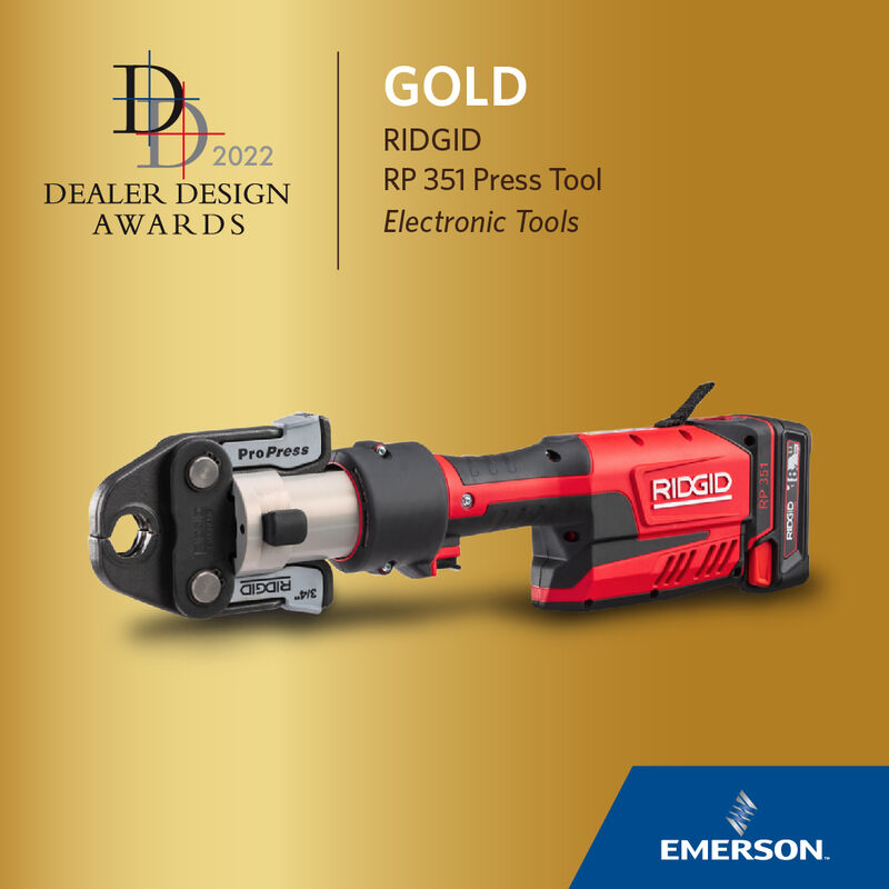

➡ See also the RIDGID RP 350 Press Tool, which is compatible with the NEW STRUTSLAYR

STRUTSLAYR, The Strongest & Most Powerful Strut Channel Cutter – the first mobile-dedicated strut tool on the market, creates clean, square strut cuts free from chips and burrs with a single pull of the trigger, and in five seconds or less.
Compatible with RIDGID 32kN press tools*, the STRUTSLAYR strut cutter offers reduced risk sparking when compared to grinders and chop saws and still manages to produce a clean, consistent cut just by pulling the trigger.
A day in The Life Of An Electrical Engineer
STRATA, specialists in Arc Flash Clothing & Protection Kits, have been working behind the scenes, connecting and collaborating with their client base to create brand new content series that highlights the raw activities that go on each day within the Energy Sector.
They are proud to officially launch their new STRATA® Protection Series with ‘The Day in the Life of an Electrical Engineer’ in collaboration with Anesco Ltd.
Meet Gheorghe. Gheorghe works at Anesco as a High Voltage Appointed Person and Technician on solar farms and battery energy storages. Watch as we follow Gheorghe across the solar wind farm and see how a faulty inverter is replaced and much more.
Thorne & Derrick understand how critical it is to have reliable, highest quality personal protection equipment (PPE), clothing and workwear available from stock at competitive prices – protecting utility workers against arc flash dangers posed during maintenance on underground electric cables, overhead line conductors or electrical equipment.
Technical Tip
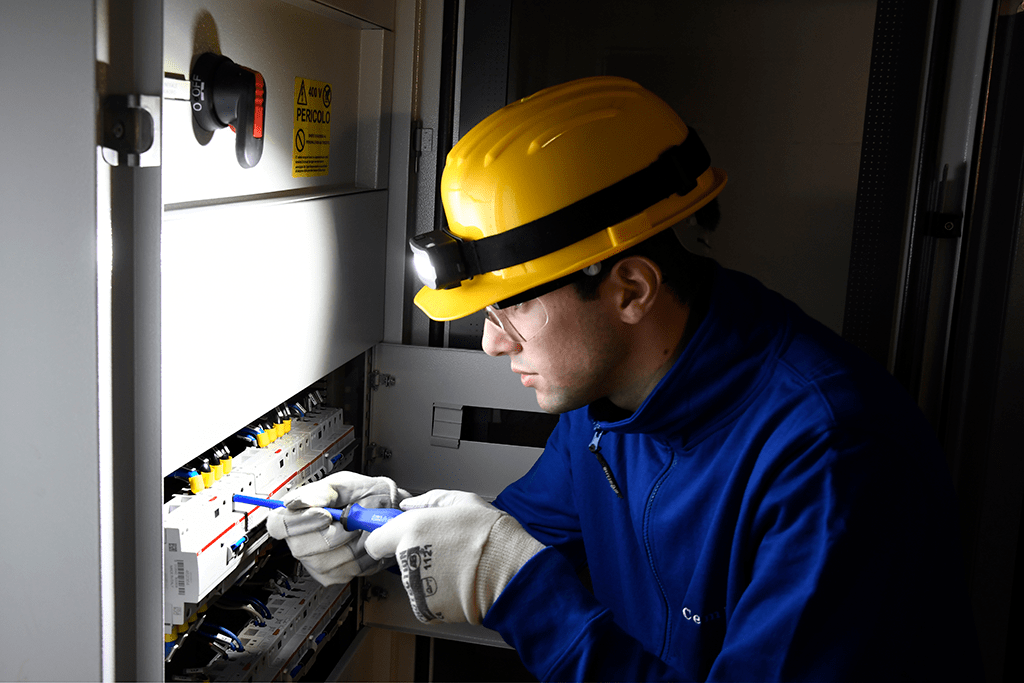
LIGHT UP ANY SITUATION WITH A PRACTICAL SOLUTION
The CEMBRE CBLIGHT (CBL) series offers a complete range of LED lights: highly practical and functional torches, lamps and portable spotlights.
Compact and easy to use, the CBLIGHT series lights are a practical solution in any situation where quick and efficient wireless lighting is required.
The range consists of COMPACT, PORTABLE, FLOOR AND TABLE TOP devices:
- EFFICIENT, COB (chip on board) LED technology
- BRIGHT, 150-3000 lumens
- LOW CONSUMPTION, from 2.5-10h battery life and high energy rating
- ERGONOMIC and lightweight, bi-component plastic handles
- PRACTICAL, double light point, with adjustable magnetic support and built in suspension hook
- ALWAYS READY with wireless charging
- FUNCTIONAL as a power bank
SECTOR SPOTLIGHT | BATTERY STORAGE
Thorne & Derrick, Specialist UK Distributors of LV HV Jointing, Earthing, Substation & Electrical Eqpt up to 66kV, provide expert technical specification, customer support and product supply from stock of an extensive range of Hazardous Area Electrical Equipment – this includes Power, Heating & Lighting products with ATEX Certification for installation in Substation Battery Rooms.
♦ Lighting – T&D can provide lighting designs to ensure lux levels are achieved in line with regulations, fittings are located correctly and meet certification requirements – we provide a comprehensive hazardous area lighting system design service.
♦ Heating – T&D can provide battery room heat loss calculations to ensure the correct heaters are specified and meet ATEX certification requirements to provide adequate comfort heating to the substation.
♦ Power – T&D can specify and supply from stocks Joints & Terminations for the connection and energisation of high voltage power cables to switchgear and transformers up to 66kV.
- Raytec | Light Fittings
- Abtech | Junction Boxes
- Craig & Derricott | Isolators
- EXHEAT | Heaters
- Marechal | Plug & Sockets
- Crowcon | Gas Detectors
- Technor | Enclosures & Control Equipment
- Roxtec | Cable Transits
- Hawke | Cable Glands
- ATEX PIR’s

Pictured | Stocked by Thorne & Derrick, the SPARTAN WL168 Zone 2 Intelligent Emergency Linear Luminaires improve light levels on this substation battery room site. On this project, the lighting brief was to replace x 4 existing 2x58W fluorescent Zone 2 fittings. The customer originally requested 5ft LED Linear alternatives, but due to SPARTAN’s high lumen output and unique modular design – which would make any ongoing maintenance quick and easy – SPARTAN WL168 provided the ideal solution. Discuss your requirements with us.
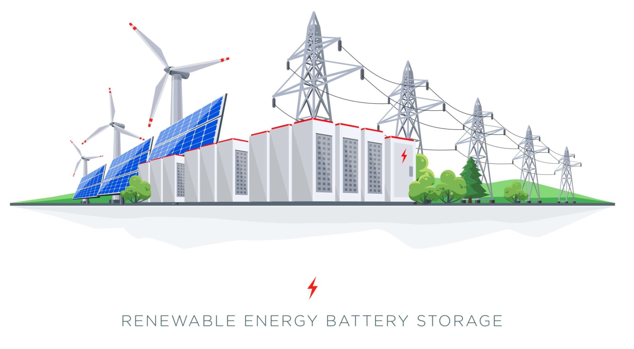
We can help | High Voltage Power, Lighting & Heating for Substation Battery Rooms
VOLTS! By,
Thorne & Derrick distribute the most extensive range of Low & High Voltage Cable Installation & Electrical Distribution Equipment to the Power Transmission & Distribution industry in the onshore and offshore wind, solar, rail, oil/gas, data centre, battery storage and utility sectors – this includes Joints, Terminations & Connectors to enable the installation of low, medium and high voltage power cables into underground trench or duct.
Key Product Categories: Connectors, Joints & Terminations MV HV | Cable Preparation & Jointing Tools | Duct Seals | Cable Transits | Cable Cleats | Cable Glands | Electrical Safety | Arc Flash Clothing & Protection | Cable Pulling | Earthing & Lightning Protection | Feeder Pillars
Main UK Stockists for: 3M Electrical, PFISTERER Connex, Nexans Power Cable Accessories (Euromold), Alroc, Ellis Patents, ABB, Roxtec, Cembre & CATU Electrical.


