

Cable Joints & Terminations HV
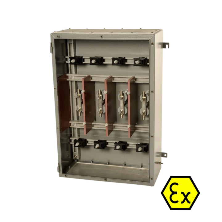
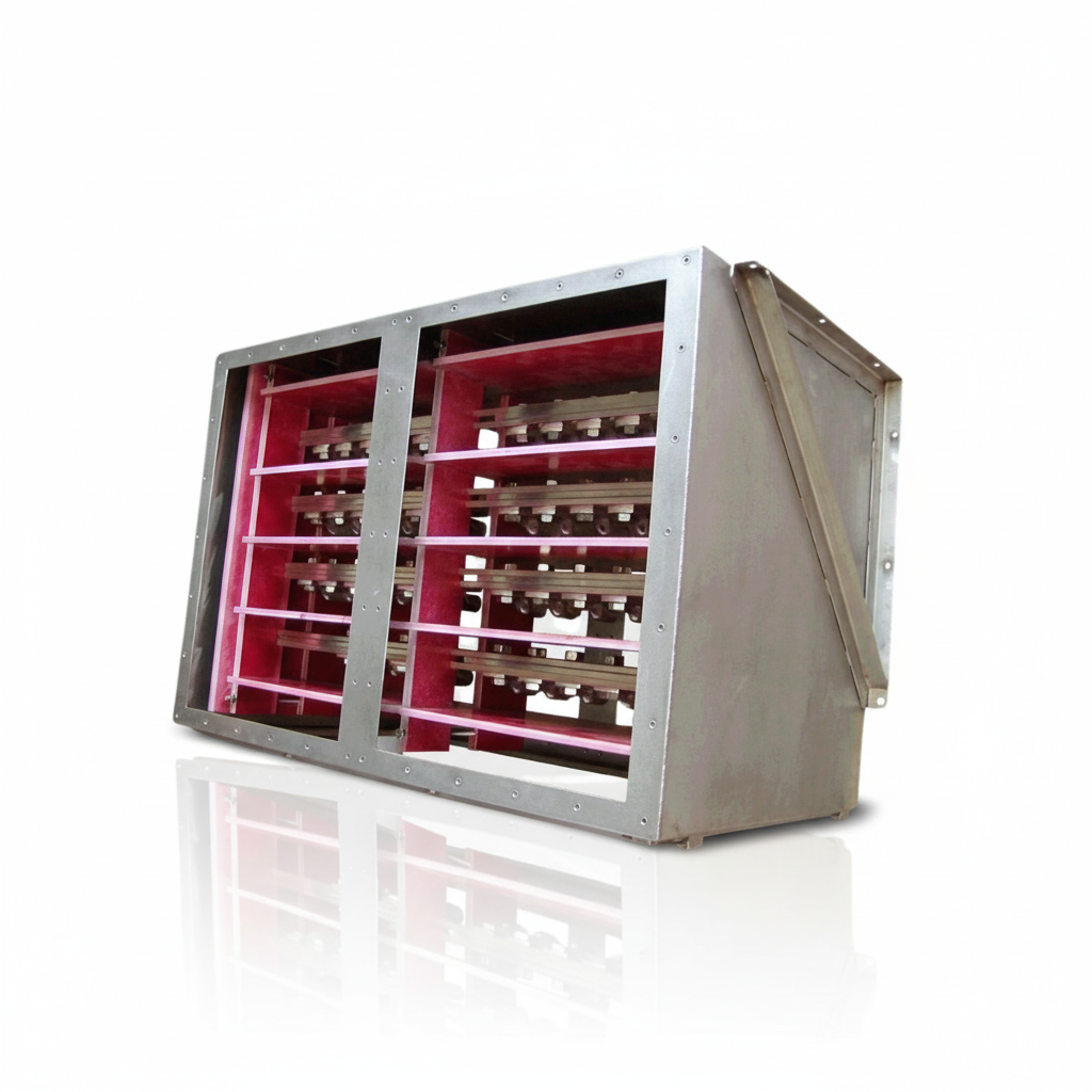
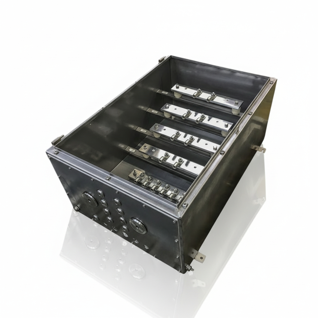
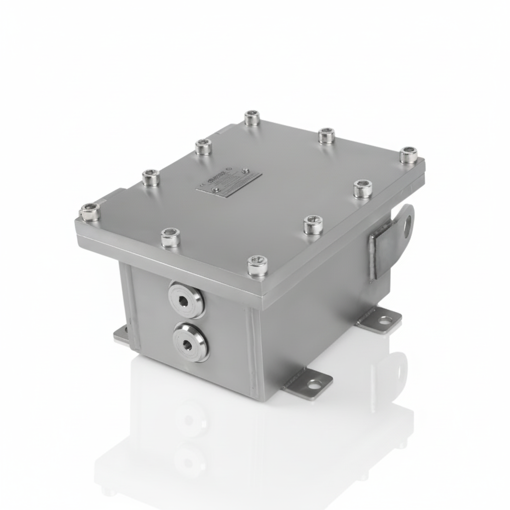
HV Junction Boxes & Electrical Enclosures for High Voltage Systems
March 18th, 2026
HIGH VOLTAGE JUNCTION BOXES & ENCLOSURES
When high-voltage power distribution and cable termination are required, safety, enclosure integrity and long-term reliability are critical.
HV Junction Boxes and Electrical Enclosures manufactured by Abtech are engineered for the safe distribution, cable termination and protection of high voltage power systems in industrial, utility and hazardous area environments.
In this range, HV junction boxes & electrical enclosures support 11kV, 33kV, 66kV and specialist high-current applications, providing dependable solutions for power transmission, distribution, subsea termination, busbar systems and fibre optic integration.
These enclosures are engineered for harsh operating conditions and are suited to applications requiring certified protection, robust stainless-steel construction, high ingress protection and safe high-voltage cable termination.
Need Help Selecting The Right HV Junction Box?
Choosing the correct high-voltage enclosure depends on operating voltage, current loading, hazardous area classification, cable size, termination arrangement and installation environment. Speak to our team for guidance on the most suitable HV junction box or electrical enclosure for your application.
Why HV Junction Boxes Are Important
- Provide safe termination and interconnection of high-voltage power cables
- Protect critical electrical connections in demanding environments
- Support reliable power distribution in industrial and utility networks
- Help maintain ingress protection and long-term enclosure integrity
- Enable compliant installation in hazardous and non-hazardous locations
Designed For High Voltage Safety, Protection & Reliability
HV junction boxes must do more than simply house cable terminations. In modern power systems they also help:
- Protect live HV terminations from moisture, dust and contaminants
- Support safe connection of 11kV, 33kV and 66kV systems
- Provide robust enclosures for onshore and offshore use
- Accommodate multiple conductors and flexible connection layouts
- Support hazardous area compliance where explosive atmospheres are present
These requirements are essential where high-voltage networks operate in challenging environments such as substations, process plants, offshore platforms, renewable energy sites and industrial facilities.


Applications For HV Junction Boxes & Electrical Enclosures
- Power generation facilities
- Industrial power distribution
- Utility and substation projects
- Offshore oil, gas and marine installations
- Renewable energy infrastructure
- Hazardous area process plants
- Subsea cable termination systems
- Control, monitoring and fibre-integrated installations
Choosing The Right HV Junction Box
Selecting the correct enclosure depends on:
- Operating voltage and system design
- Current loading and conductor size
- Hazardous area classification
- Ingress protection requirements
- Onshore, offshore or subsea installation environment
- Need for busbar systems, fibre integration or specialist compartment layouts
The correct HV junction box helps ensure safe cable termination, dependable network performance and long-term enclosure integrity in critical electrical infrastructure.

Compound Box Filling for MV End Box Refurbishment: Why the Dielectric Choice Matters
March 12th, 2026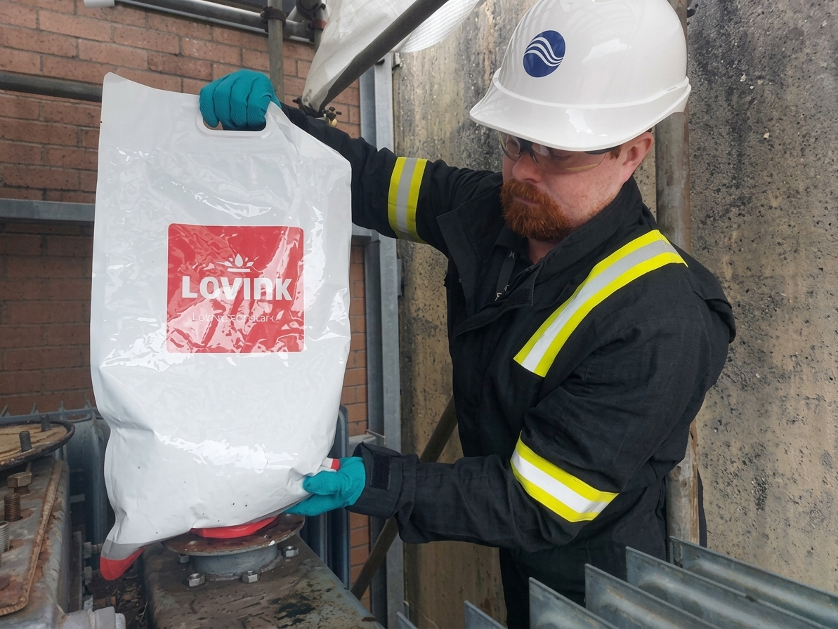
Compound Box Filling
Compound end boxes rarely get attention — until one fails.
Across ageing networks, replacement of compound-filled end boxes is becoming more frequent, particularly where original insulation systems have deteriorated and air insulation is not practical because separation distances are limited. In these situations, the replacement dielectric is not a minor detail; it is central to long-term reliability.
When specifying compound box filling for refurbishment works, the goal is not simply to refill the box. The dielectric has to maintain insulation performance over time, tolerate operational movement, and resist the conditions that caused deterioration in the first place.
At Lovink Enertech, LoviSil® provides a purpose-engineered solution for compound end box refurbishment. Unlike curing alternatives, LoviSil® remains permanently fluid, allowing it to move with conductor expansion and contraction under load. Solidifying compounds cannot accommodate this movement; over time they form voids, and voids lead directly to partial discharge and eventual breakdown.
Why Compound Box Filling Matters
In MV end box refurbishment, the dielectric choice directly affects service life, insulation integrity and future maintenance. A fluid dielectric offers an important practical advantage because it can move with conductor expansion and contraction during load cycling, helping to reduce the formation of voids that can lead to partial discharge.
LoviSil® requires no mixing, can be poured straight from the bag, and does not require greasing of the box prior to installation. It is also fully compatible with residual pitch or bitumen, meaning complete removal of legacy compound is not always necessary.
With a minimum dielectric strength of 21 kV/mm, LoviSil® delivers insulation performance equivalent to XLPE. It resists moisture ingress and forms a sealing barrier if moisture attempts to enter, helping prevent migration deeper into the system.
Key Advantages
- Permanently fluid dielectric – moves with conductor expansion and contraction under load
- Reduces void formation risk – helping to minimise partial discharge and premature breakdown
- No mixing required – can be poured straight from the bag for simpler installation
- No box greasing needed – helping reduce preparation time on site
- Compatible with residual pitch or bitumen – complete removal of legacy compound may not be necessary
- High dielectric strength – insulation performance equivalent to XLPE
- Simple re-entry – drainable for easier future maintenance and intervention

A Practical Maintenance Advantage
Re-entry is simple. Release the bolts at the base of the faceplate and the LoviSil® drains into a container. No cutting. No effort. Just drain and go.
For asset owners, this provides a cost-effective alternative to full end box replacement while restoring dielectric performance and extending service life.
Recent failures involving replacement compound-filled end boxes highlight a recurring issue: choosing the wrong dielectric solution only delays the problem.
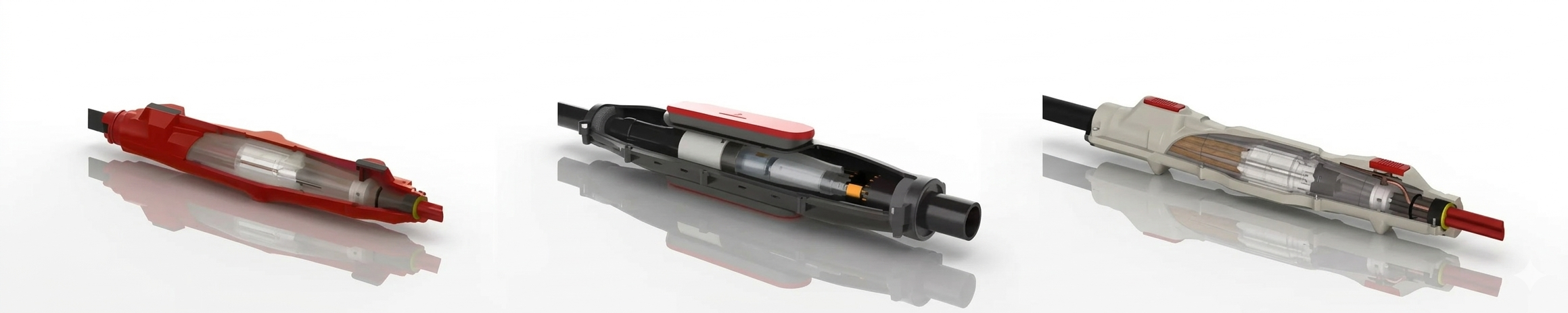
Overview of the Lovink Cable Joint Range
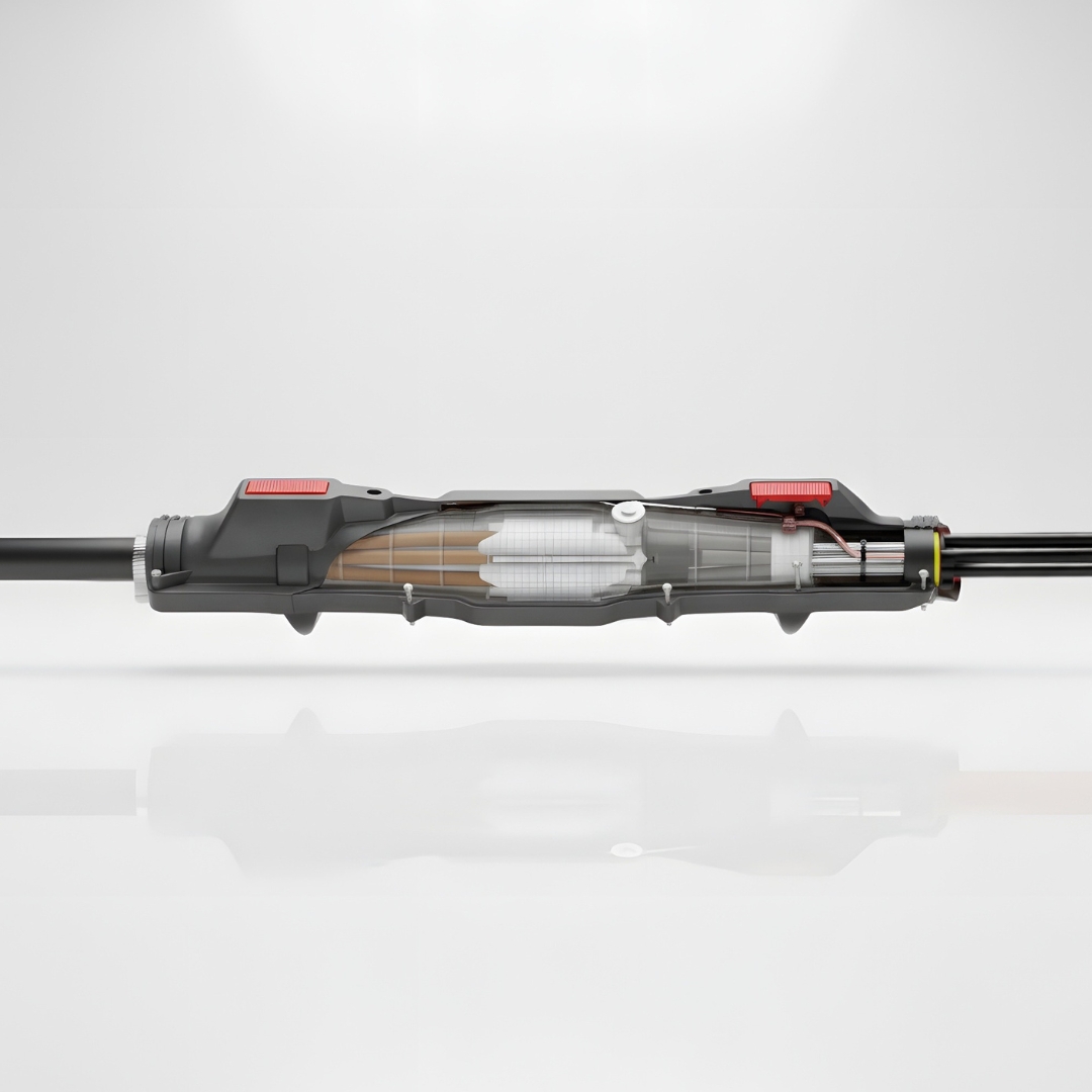
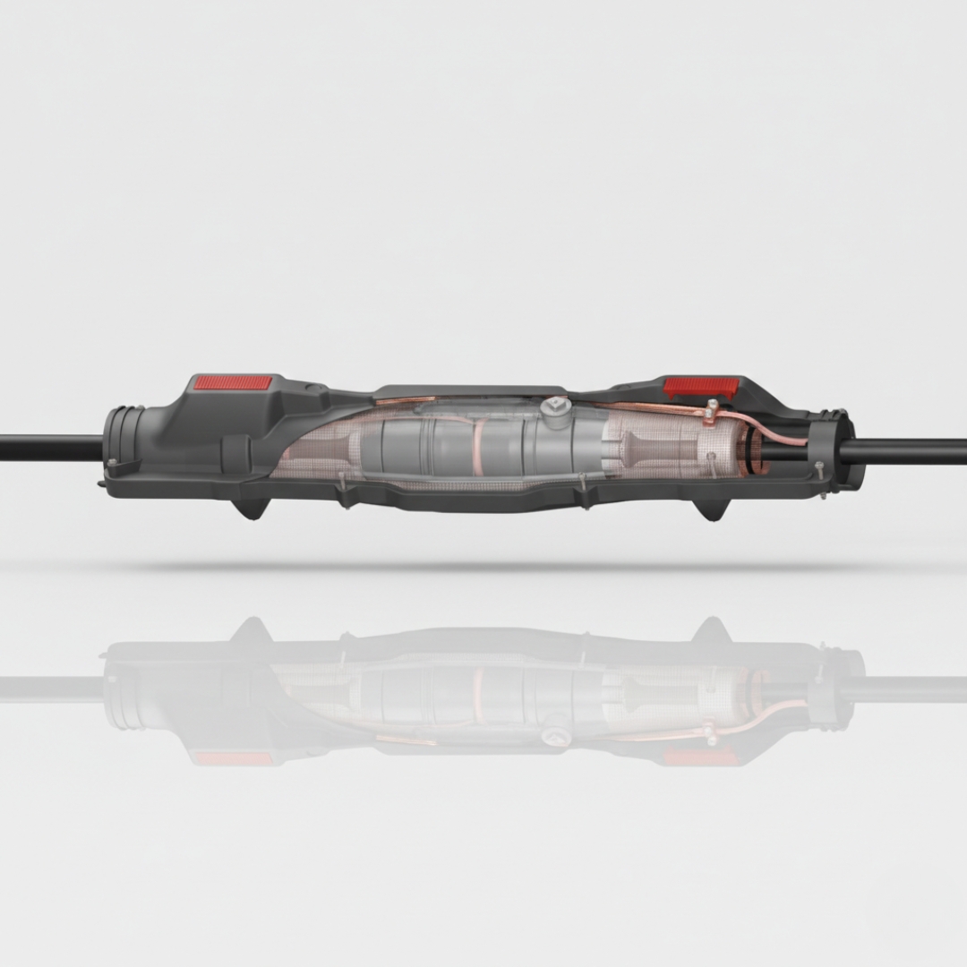
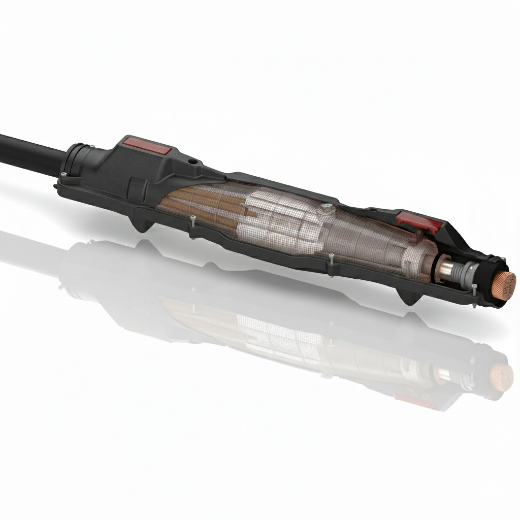
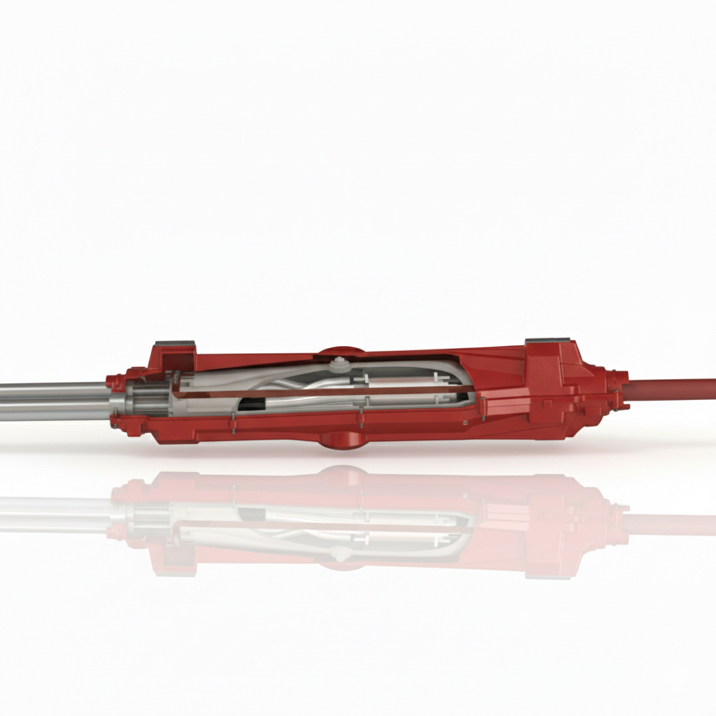
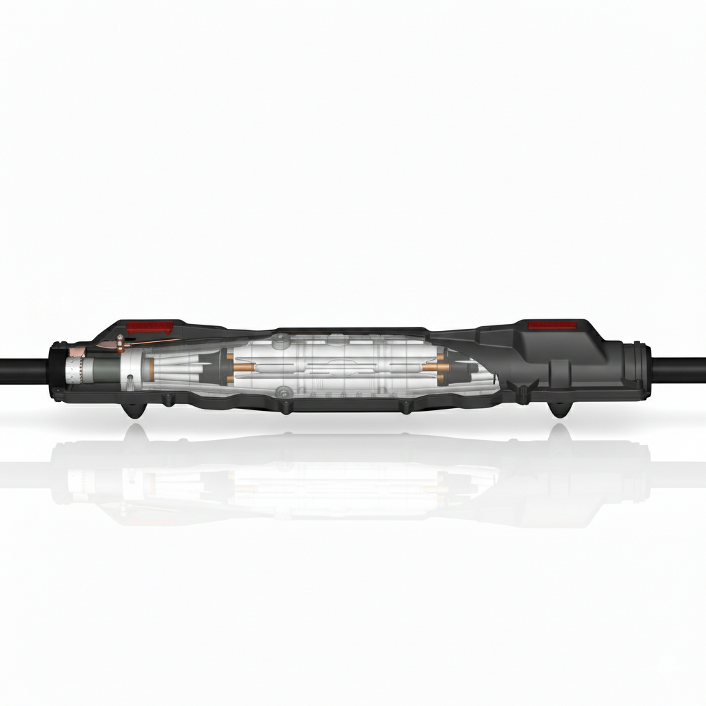
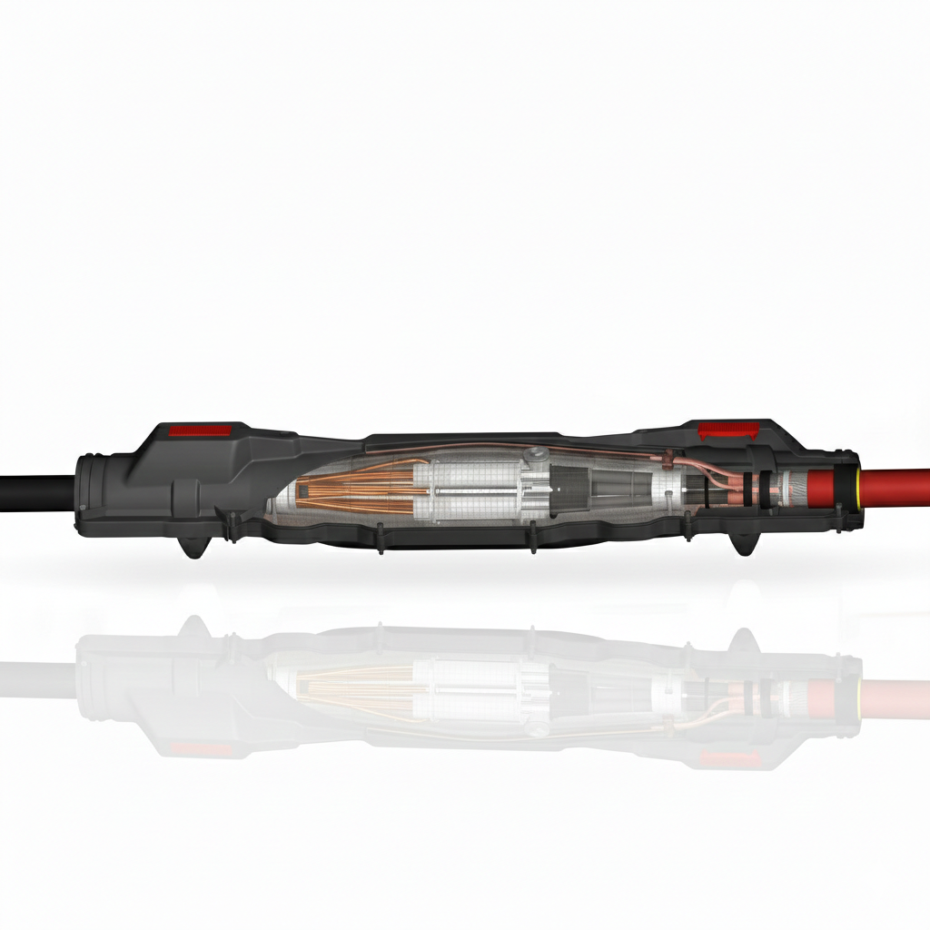
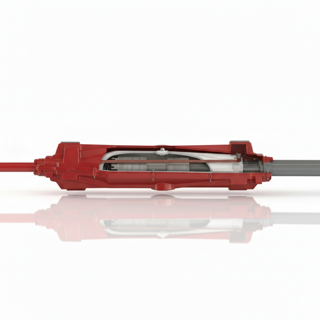
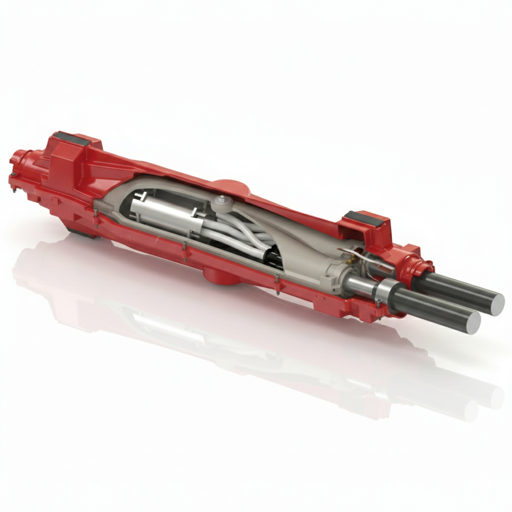
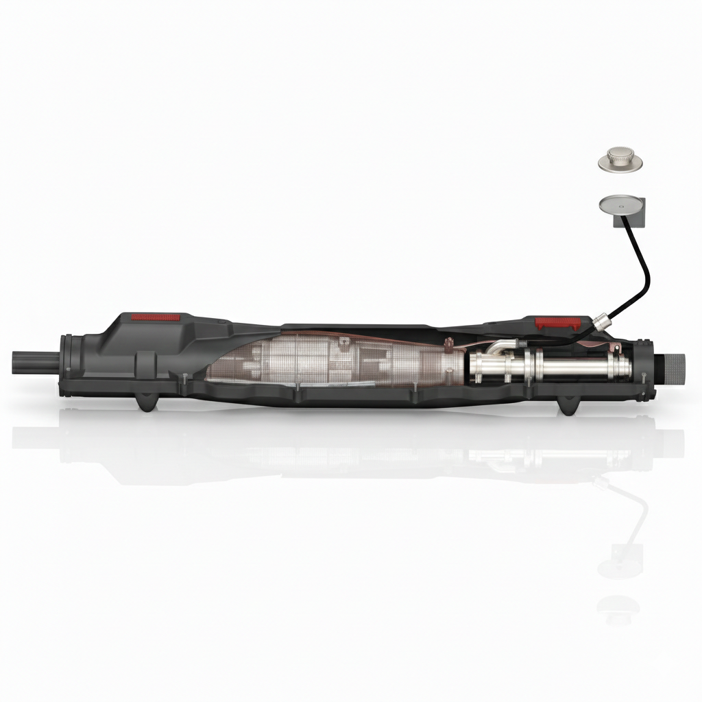
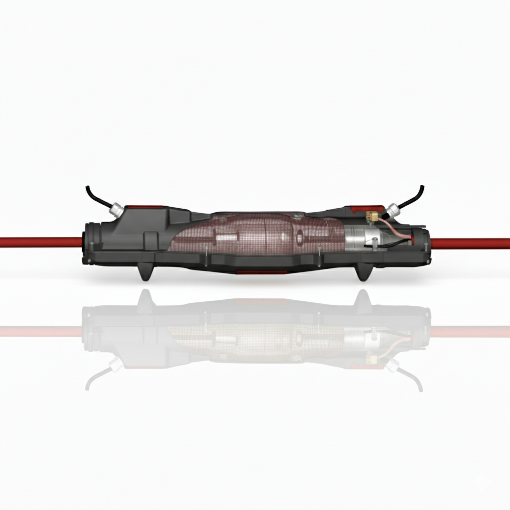
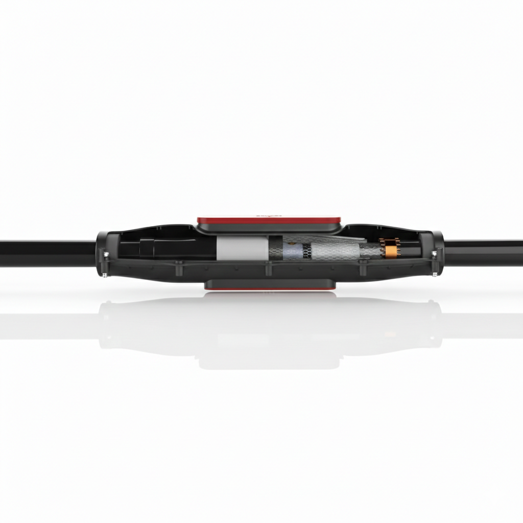
Alongside solutions for compound box filling and end box refurbishment, Lovink offers a broad range of medium voltage cable joints designed for ageing infrastructure, upgrades, repairs and new connections across 11kV and 33kV networks.
Below is an overview of the 11 Lovink joint categories, each developed to suit specific installation and network requirements.
Lovink MV Cable Joints
A complete range of medium voltage cable jointing solutions for repairs, transitions, upgrades and new underground cable connections.
|
Transition Cable Joints For connecting legacy paper-insulated cables to modern polymeric MV cables. |
Straight Cable Joints For straight-through MV cable connections requiring continuity and insulation reliability. |
|
Stop-End Joints A sealed solution for terminating underground MV cables safely and securely. |
Branch Joints Designed to create branch connections within MV distribution networks. |
|
Cable Repair Joints Ideal for repairing damaged cable sections without replacing the full route. |
Extended Resin Cable Joints Provides extra sealing and bonding space for more demanding installations. |
|
Feed-In Cable Joints For connecting new power sources into existing underground MV cable systems. |
Loop Cable Joints A compact solution for internal looping arrangements in restricted spaces. |
|
Oil Refill Cable Joints Designed for paper-insulated lead-covered cables where oil retention is essential. |
Crossbonding Cable Joints Used to help manage sheath losses and improve MV cable system efficiency. |
|
Compact Cable Joints A space-saving MV joint solution for ducts, trenches and compact installations. |
Full Lovink Range View the full Lovink cable joint range for MV refurbishment and connection projects. |
Conclusion
Compound-filled end boxes often only get attention when something goes wrong. But the choice of compound box filling has a direct impact on insulation performance, moisture resistance, re-entry and long-term reliability.
Where refurbishment is the preferred route, Lovink’s LoviSil® offers a practical and technically robust alternative to full end box replacement. Combined with Lovink’s wider MV joint portfolio, it supports utilities, contractors and network operators working to extend asset life and improve resilience across ageing cable systems.
Need Support with Compound Box Filling or MV Cable Joints?
Thorne & Derrick supply Lovink LoviSil® solutions and the wider MV cable joint range, with technical support for refurbishment, repairs and new cable connections.
Slaters Electricals | UK’s Largest Stock of New & Refurbished Power Distribution Equipment
October 29th, 2025
Since 1923.
-
uploaded by Chris Dodds | Thorne & Derrick Sales/Marketing Manager
Slaters Electrical are experts in the provision of LV MV HV Power, Distribution & Cast Resin Transformers, Switchgear, Installation,  Maintenance, Site Services & Spares.
The Slaters Electricals installation division primarily operates from a dedicated base in Sheffield, with additional skilled engineers based at their Head Office and main works in Newcastle upon Tyne.
From these two sites Slaters Electricals offers a range of HV MV and LV installation and cable work services covering the whole of the UK.
➡ Contact t: 44 (0)191 414 2916 e: [email protected]



Switchgear & Transformers
MV HV Medium & High Voltage Power
The following photographs are published with the kind permission of Slaters Electricals and demonstrate their leading technical skills, knowledge and expertise in providing turnkey Medium & High Voltage Power Distribution solutions.
- 2no New 2000kVA 11kV/433V Midel Filled Tier 1 Distribution Transformers + LV Boxes to accommodate Schneider Canalis Busbar Trunking System
- New 7 Section Schneider Ringmaster Switchboard consisting of 5no 630A CE6-T4/21 & 2no 200A CE2-T2/21 Circuit Breakers
- 30V Battery Tripping Unit
- HV Cable Works & Cable Containment
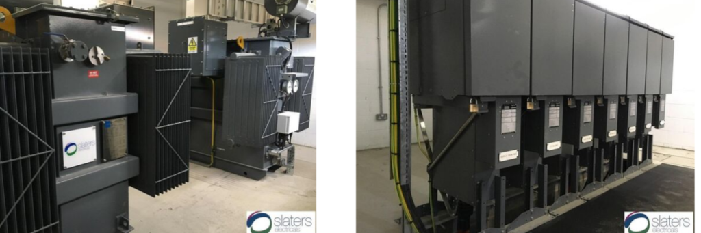
All MV HV Power Distribution Switchgear & Transformers are checked, refurbished and tested by skilled time-served engineers prior to delivery.
- 11kV/110V AC Voltage Transformer fixed and moving portions for GEC VMX Switchgear despatched to a UK DNO on a same-day turnaround following a catastrophic failure in a distribution network Substation. Slaters Electricals provide a rapid-response to emergency power restoration enabled by extensive stocks of legacy and current technology switchgear and transformer spare parts at their 100,000 square foot facility.
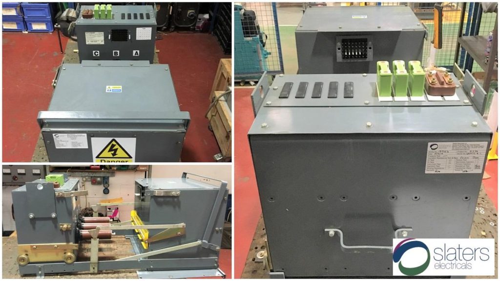
Emergency deliveries of Power Distribution & Switchgear are achieved nationwide supported by the largest UK spares stocks and same day “load and run” delivery fleet.
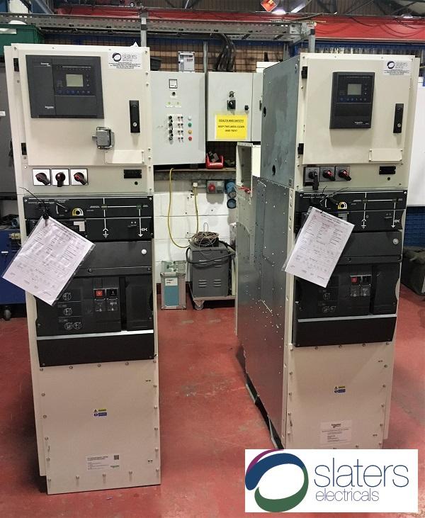
- 2no refurbished Schneider GenieEvo VC2 200A Circuit Breakers after completing tests at Slaters Electricals – the range of refurbished switchgear stock includes most current production types including Schneider GenieEvo & Ringmaster, Hawker Siddeley/Brush Eclipse, ABB UniGear & ABB SafePlus as well as the widest available range of legacy UK manufactured types including Alstom, Brush, GEC, Long & Crawford, Reyrolle, South Wales, Yorkshire etc. Whether you need a spare part, a single extension panel or a full replacement switchboard, you can contact their Sales Engineers.
- New 2000kVA 11kV/433V Tier 1 Distribution Transformer complete with close coupled Schneider CN2-T1 200A Circuit Breaker and refurbished 3200A ABB SACE ACB Feeder Cabinet, contained within a custom fabricated tranformer bund. Slaters Electricals site services division attends site to complete MV HV & LV cable works and containment plus installation-commissioning as part of a full supply and install MV Power Distribution solution including GRP enclosure and battery tripping unit.
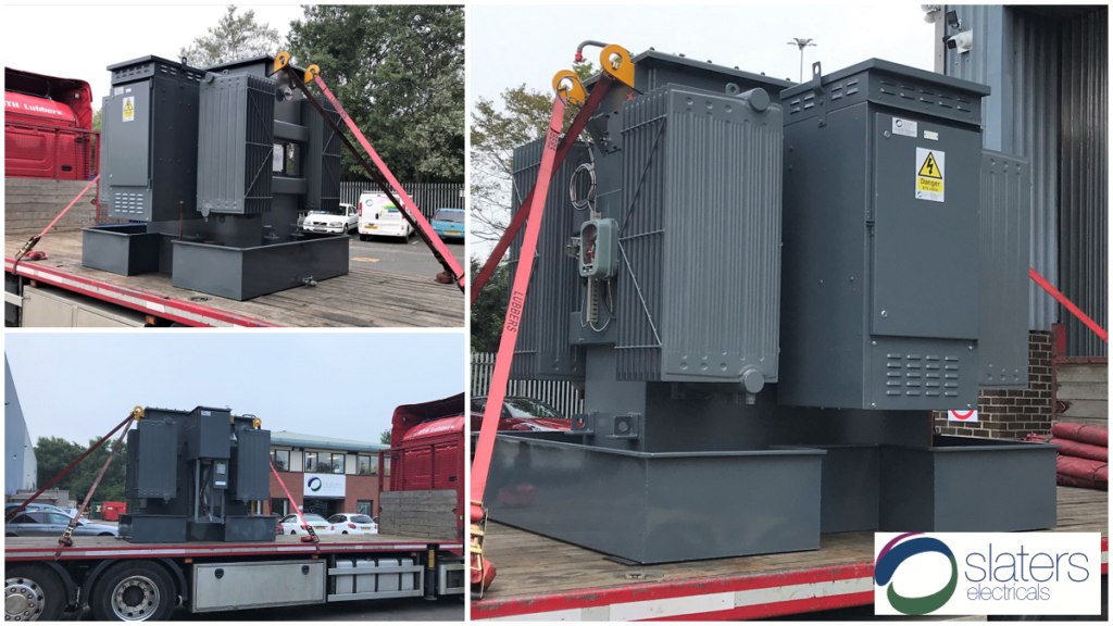
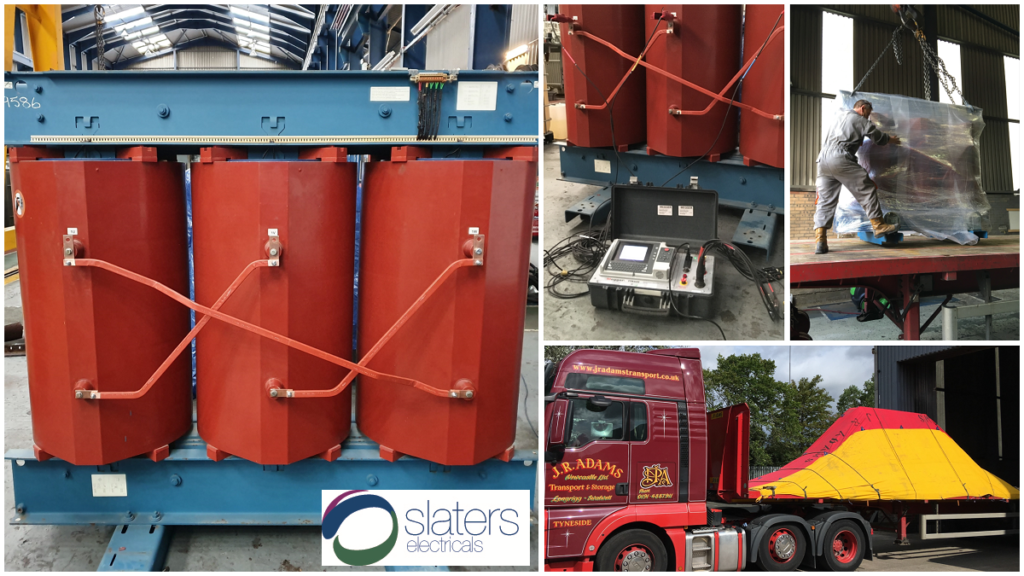
2.5MVA 11000/433V Dyn11 Cast Resin MV Medium Voltage Transformers
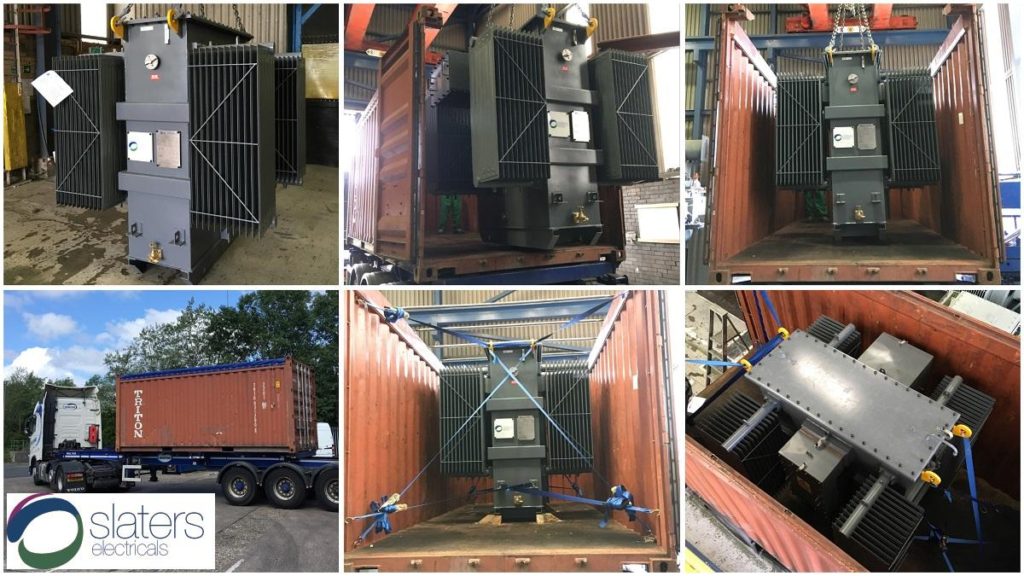
2500kVA 11kV/433V Tier 1 Distribution Transformer
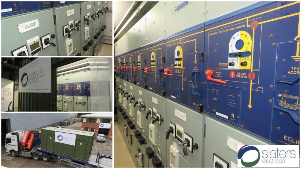
Fully Refurbished 11kV Eclipse 20ft Containerised Switchboard | Hire Options
THORNE & DERRICK
Thorne & Derrick are national distributors of LV, MV & HV Cable Installation, Jointing, Substation & Electrical Equipment – servicing businesses involved in cabling, jointing, substation, earthing, overhead line and electrical construction at LV, 11kV, 33kV, 66kV and EHV. Supplying a complete range of power cable accessories to support the installation and maintenance of low/medium and high voltage voltage power systems:
- Slip-on Cable Terminations
- Cold-shrink Cable Terminations
- Heat-shrink Cable Terminations
- Cable Joints – Heat & Cold-shrink
- Separable Connectors (Euromold)
- Surge Arresters & Switchgear/Transformer Bushings
Key Product Categories: Duct Seals | Cable Cleats | Cable Glands | Electrical Safety | Arc Flash Protection | Cable Jointing Tools | Cable Pulling | Earthing | Feeder Pillars | Cable Joints LV | Joints & Terminations MV HV
Pioneering Safety in Onshore & Offshore Wind: First Graduates of New GWO High Voltage Cable Pulling Standard
August 12th, 2025
The Wind Academy
The Wind Academy, the UK leading facility delivering GWO and Technical Trade Training Courses, has marked a major milestone in onshore and offshore wind technician training with the successful delivery of the first-ever GWO High Voltage Cable Pulling (HVCP) Training Standard.
Hosted at their brand-new Training Facility at the Port of Blyth, this pilot programme has produced some of the very first professionals in the world to gain certification under this innovative new standard — developed by the Global Wind Organisation (GWO) to boost safety, reduce cable damage, and improve operational uptime across the wind sector.
What is the HVCP Module?
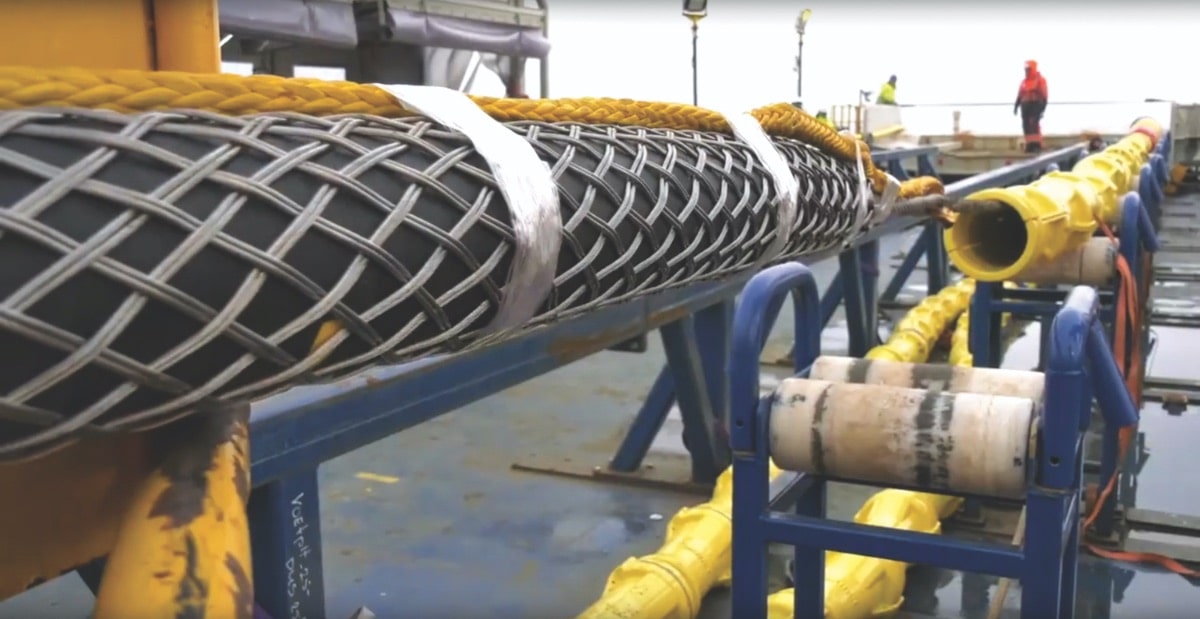
The HVCP module forms part of the new GWO High Voltage Training Standard and equips participants with the skills, safety awareness and confidence to carry out high voltage cable installation both onshore and offshore.
Aimed at commissioning and service technicians, this standard supports work in HV operations or cable pulling under a Safe System of Work (SSOW). The HV Standard has been highly requested by many of the leading members of the Global Wind Organisation with input from Cubico Sustainable Investments, ENERCON, ENGIE, GE Vernova, Nordex Group, Northland Power Inc., Ørsted, RWE, Siemens Gamesa, SSE Renewables and Vestas.
Key Learning Areas
The HVCP module covers the following core areas:
- Safe handling & cable pulling — techniques for working safely in wind-turbine environments
- Damage identification & inspection — how to spot and document cable faults during and after installation
- Mechanical stresses & tool use — understanding loads and selecting/using the right tools
- Basic electrical field theory — essential HV concepts to work safely around cables
- Team coordination & communication — roles, signalling and handovers on complex jobs
- Risk mitigation & PPE — ergonomics, PPE and safe work practices
- Final cable loop installation & restoration — finishing checks and site reinstatement

Why This Matters for the Industry
By standardising HV cable pulling procedures and ensuring rigorous training, the new GWO HVCP standard helps:
-
Prevent costly cable damage during installation
-
Protect worker safety in challenging offshore conditions
-
Maintain uptime and reliability of wind farm assets
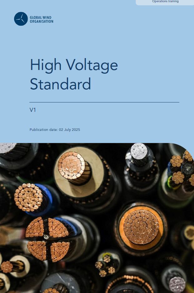
GWO High Voltage Standard
The GWO High Voltage Standard will enable participants to support work related to high voltage equipment and systems as per the specific module focus area and detailed topics within. The High Voltage Standard is divided into the following two modules:
High Voltage Operations
The training target audience includes workers required to operate and make safe high voltage equipment and systems, under a documented safe system of work, including commissioning technicians and service technicians, both onshore and offshore.
High Voltage Cable Pulling
The training target audience includes workers required to perform or supervise high voltage cable pulling operations, including offshore pre-assembly technicians, as well as installation technicians and service technicians completing replacement of high voltage cables, both onshore and offshore.
HV Jointer Training at the Wind Academy
The Wind Academy also provides brand-specific Cable Termination Courses for leading cable accessory manufacturers including Nexans (Euromold), Pfisterer (Connex), 3M Electrical, and NKT.


Thorne & Derrick
Leading Specialist Electrical Distributor to the Global Renewable Energy Industry
Thorne & Derrick supply High Voltage Cable Accessories, Jointing Tools & Power Distribution Equipment up to 66kV – we hold several Framework Supply Agreements with international energy providers, OEM’s and High Voltage Power Energy Companies.
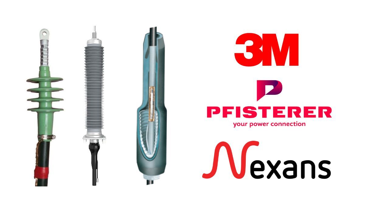
From the largest stocks in the UK & EU we supply global projects with HV Cable Accessories to energise projects – this includes Nexans Euromold, Pfisterer Connex & 3M Cold Shrink Separable Connectors, Joints & Terminations at 11kV/33kV/66kV.
This is complemented by the most extensive stocks of Cable Preparation, Cutting, Crimping & Spiking Tools for insulation, screen, sheath removal of MV & HV cables including Alroc, Ripley, Hivotec, Cembre, Klauke, Boddingtons and PENTA.

Supplying Cable Termination, Jointing, Pull-in & Electrical Equipment up to 66kV
Cold Shrink Glands for MV HV Cables
May 21st, 2025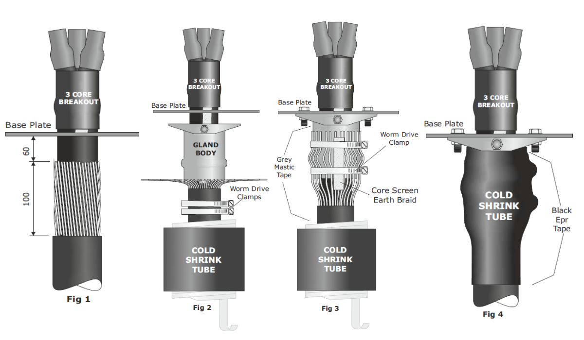
How to Install SPS 180 & SPS 193 Cold Shrink Cable Glands
To suit 3 Core SWA Armoured XLPE Cables, 3.6kV (3.3kV) to 36kV (33kV)
Reference Numbers: SPS 180(CS) and SPS 193(CS)
In this Post, we present a step-by-step installation guide for the SPS 180(CS) and SPS 193(CS) Cold Shrink ‘Bolt-On’ Type Cable Glands. These “top-hat” glands are designed to connect and gland 3-core armoured XLPE cables from 3.6kV to 36kV, providing a reliable and easy-to-install solution for Cold Shrink termination and are distributed by Thorne & Derrick.
Note:- Fig 1 shows one possible cable gland configuration, in some situations it may be necessary to position the 3 leg heat shrink boot body below the gland plate to gain space within the cable box. If cable is non armoured, additional strain may be put on the heat shrink tube to ensure cable is supported by cable cleats to provide additional strain relief.
Step-by-Step Installation Guide
1. Cable Preparation
-
Before opening up the armour wires, ensure the cold shrink tubes and the two worm drive clamps are in position.
2. Armour Wires
-
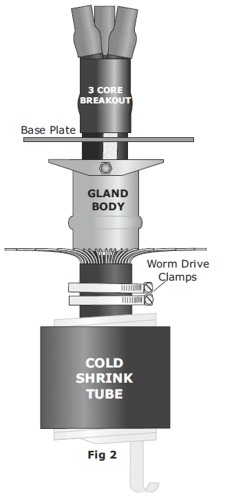
Open up the wire armours as shown in Fig 2.
3. Cable Gland Body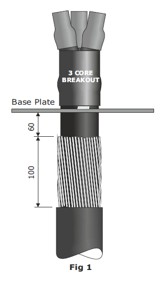
-
Slide the metal cable gland body over the cable.
Note: The cable gland body itself can, in most cases, be positioned after completing the cable termination.
For Steel Tape Armoured Cable:
Prepare to the same dimensions shown in Fig 1 and follow section 7 (see below).Configuration Tip:
Fig 1 shows one possible configuration. In some cases, you may need to position the 3-leg boot body below the gland plate to gain space within the cable box.Non-Armoured Cable Warning:
Additional strain may be placed on the shrink tube. Ensure the cable is supported by cable cleats to provide strain relief.
4. Final Connections
-
Complete the final connections of the cable termination before bolting the cable gland body in place.
5. Bend Armour Back
-
Bend the armours back over the cable gland body.
6. Clamping
-
Using the worm drive clamps, connect the cable armours and screen earth braids to the cable gland body as shown in Fig 3. Ensure the cable clamps are tight.
7. Cover Edges
-
Cover any sharp edges and the clamp buckles with PVC tape.
If Steel Tape Armoured:
Unwind the electrical tape below the bottom of the cable gland, re-wrap around the cable gland body, and secure with worm drive clamps.
8. Moisture Seal
-
To provide a moisture seal, stretch and apply a turn of grey mastic tape around:
-
The top of the metal cable gland body.
-
The outer cable jacket.
-
This ensures that the cold shrink tube will recover properly onto the tape.
9. Apply Cold Shrink
-
Position the cold shrink tube.
-
Begin pulling the plastic spiral carefully.
-
Do not pull the spiral straight.
-
Wrap it around the cable to avoid snagging.
-
10. Secure Ends
-
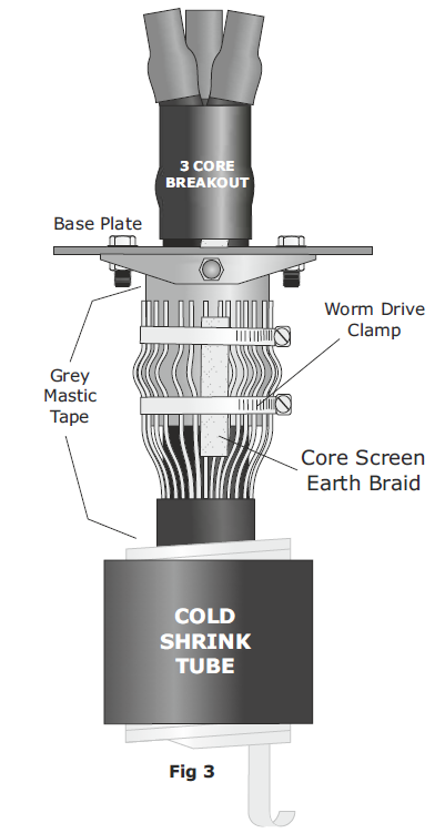
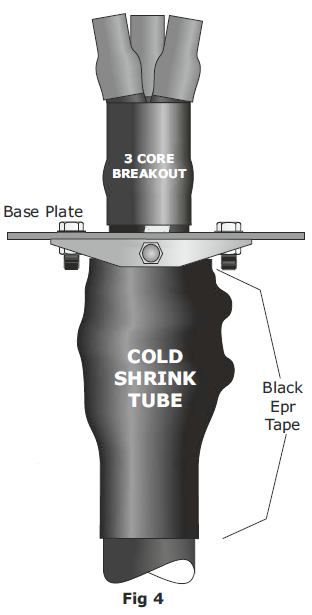
Once fitted, apply the provided black EPR tape at both the top and bottom of the tube.
Figures for Reference
-
Fig 1: Base plate and initial configuration
-
Fig 2: Wire armour open-up
-
Fig 3: Clamp setup with screen earth braid
-
Fig 4: Final assembly with cold shrink and sealing tapes
Cable Glands Distributed from Stock by Thorne & Derrick | the 501/453 range of Universal Cable Glands manufactured by Hawke are suitable for the mechanical retention, glanding and termination of LV MV HV Power Cables with steel wire armour, steel wire braid or steel tape armour.


Shrink Polymer Systems heatshrink cable joints and terminations suit all types of MV-HV electrical cables (single or multi-core) with or without armour or lead sheaths – zero halogen and fire resistant cable joints are also available.


