IEC61914 – Calculating Short Circuit Forces To Specify Compliant Cable Cleats
Uploaded By Chris Dodds – Thorne & Derrick Sales & Marketing Manager
IEC 61914
Why Specify Cable Cleats?
“A cable cleat is a device designed to provide securing of cables when installed at intervals along the length of the cables”
taken from IEC 61914 Cable Cleats For Electrical Installations
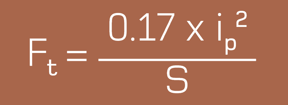
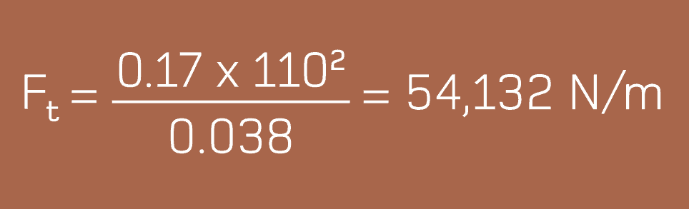
Where the system peak fault current and the cable diameter are known, the formula above, excerpted from the international standard IEC 61914, can be used to calculate the forces between two conductors in the event of a 3 phase fault in order to specify the correct type of cable cleats.
Sub-standard or under-specified cable fixings including cable cleats and cable ties can cause catastrophic damage to infrastructure, power and life – for this no scientific formula exists to calculate the costs of power outage, plus the “nuisance factor”, downtime and consequential losses of reputation. Financially, that cost is immeasurable.
♦ Cable Ties
♦ Cable Cleats
Cable cleats are designed and specified to withstand those forces exerted by the cable in the “axial” direction in most types of cable installation, including Flexible Cable Systems and Rigid Cable Systems.
i) Flexible Cable Systems – where the LV-HV cables are “snaked” either vertically or horizontally, the cables can expand and contract freely between the fixing points.
ii) Rigid Cable Systems – where the LV-HV cables are rigidly fixed and longitudinal thermo-mechanical force is withstood by the combination of the stiffness of the cable, the cable cleat, reaction force and the rigidity of the support structure.
IEC 61914:2009 specifies requirements and tests for cable cleats and intermediate restraints used for securing cable in electrical installations.
Cable cleats provide resistance to electromechanical forces where declared – this standard includes cable cleats that rely on mounting surfaces specified by the manufacturer for axial and/or lateral retention of cables.
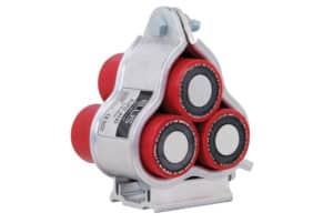
IEC61914 applies to the management and safe retention of all cable configurations and voltages (LV Low Voltage | MV Medium Voltage | HV High Voltage) including bundled, quadrafoil (quad cleats) or single cables installed in 3 phase formation using trefoil cable cleats.
Electrical design engineers and specifiers specify power cables from which the maximum anticipated short circuit load can be calculated.
This data enables the calculation of the force between the cable conductors in a short-circuit situation – cable cleats installed to cable containment (whether cable tray, ladder or basket) are in turn specified at the correct spacing to contain potential short-circuit forces generated by the low/high voltage power cable system.
The aspects of construction and performance covered by IEC 61914 include:
Material type – i.e. metallic, non-metallic or composite
Minimum and maximum declared service temperatures
Resistance to impact at the minimum declared operating temperature
The ability of the cleat to withstand axial slippage forces
Resistance to electro-mechanical forces – i.e. the ability of the cleat to withstand the forces between the cables in the event of a short-circuit
Resistance to UV and corrosion
Flame propagation
The strength of a cable cleat is often determined using a mechanical tensile test.
However, the results may be misleading because the force is applied in a slow and controlled manner, which does not replicate fault conditions.
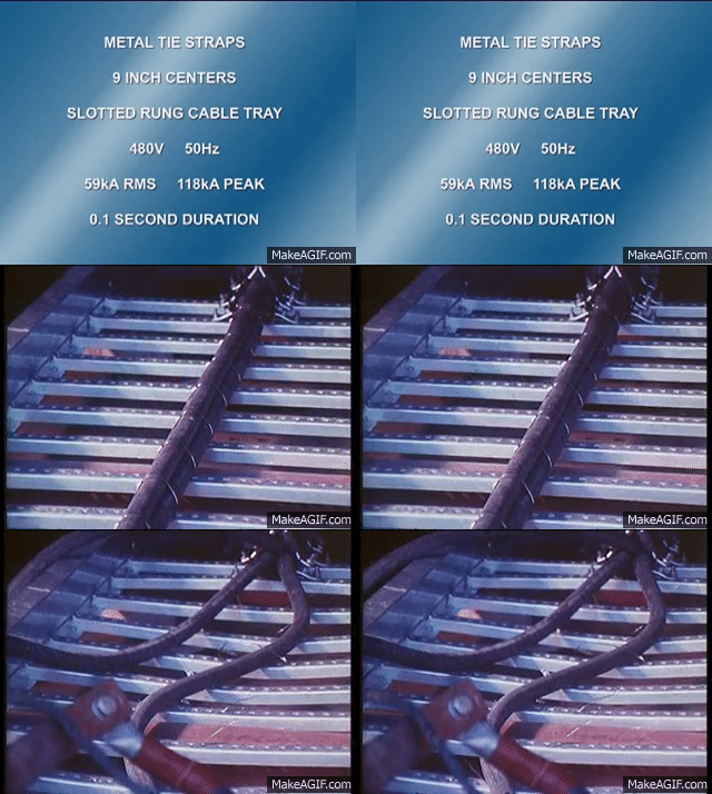
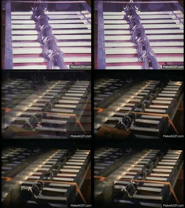
In a short-circuit fault the forces are applied almost instantaneously and oscillate in every direction. Experience shows that a cleat that survives a mechanical tensile test at a given force will not necessarily survive a short-circuit test, even if forces are the same.
IEC 61914:2009 also provides formulae to enable the theoretical forces between conductors in the event of a short circuit to be calculated.
• Ft = maximum force on the cable conductor in Newton/metre (N/m)
• Ip² = peak short-circuit current in the kiloamp (kA)
• S = distance between the centrelines of the conductors in metres (m)
Once the Ft in N/m has been determined then the force for each potential cable cleat can be calculated.
For Example
Metric cable ladder typically has rungs at 300mm intervals, so cable cleat spacing is usually a multiple of this distance. So, Ft x 0.3 gives the force a cleat will see if spaced at 300mm, Ft x 0.6 for 600mm etc.
Ft x cable cleat spacing can then be compared to the maximum recommended mechanical loop strength of the cleat and then the cleat type and spacing can be selected.
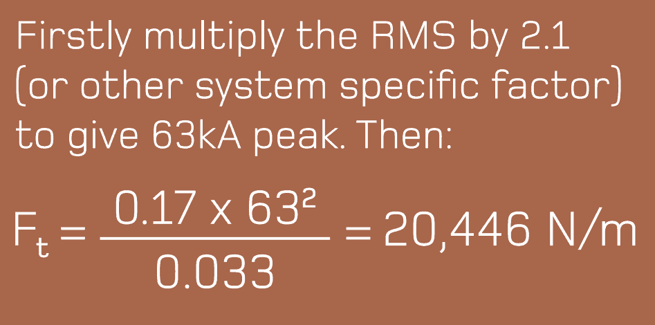
The formula uses peak current, however this is often unavailable with a Root Mean Square (RMS) value given instead – to calculate the peak current from the RMS, IEC 61914-1 Low Voltage switchgear and controlgear assemblies is commonly referred to, which uses the following multiples:
10 – 20kA = 2 21 – 50kA = 2.1 51kA = 2.2
Cable Cleat Calculations
Example 1
Peak fault: 110kA
Installation: Cable Ladder
Cables in trefoil with an outside diameter of 38mm.
Ft2 x Cleat Spacing
Required Loop Strength
0.3 for 300mm
16,240 N per cleat
0.6 for 600mm
32,480 N per cleat
0.9 for 900mm
48,718 N per cleat
1.2 for 1200mm
64,958 N per cleat
This force per distance can then be compared to different cleat loop strengths to ascertain the appropriate cleat and spacing requirements for specification. In this example, the Ellis
recommendation was for Vulcan+ cleats (LS: 36,000) spaced every 600mm, or Emperor cleats (LS: 63,000) every 900mm.
The overall length of the LV-HV cable run will determine the total number of cable cleats required – the spacing requirements for cleats is subject to cable formation, diameter and short circuit rating but quantity of cable cleats is a factor of the cable circuit length.
Example 2
RMS fault: 30kA
Installation: Cable Ladder.
Cables in trefoil with an outside diameter of 33mm
IEC 61914 has provided a standardised method for conducting a short-circuit test and a definition of the criteria for a pass. It does though allow for a significant degree of latitude and so caution must be employed when interpreting results. Note should also be taken of the full report as opposed to just its headline page.
Short-Circuit Testing
There is a major difference between the short-circuit withstand requirements of a cable and the short-circuit withstand of a cable cleat.
The former is concerned with cable degradation as a result of temperature rise (thermal stress heating), while the latter is concerned with cable retention as a result of electromechanical forces.
Typical installation specifications that have been derived from the thermal withstand of the cable would require a short-circuit withstand of 63kA for 1 second or 40kA for 3 seconds.
A short-circuit test for a cable cleat does not consider this heating effect, and instead concentrates entirely on the destructive electro-mechanical forces at peak, followed by a short term decaying RMS.
The international standard IEC 61914 requires a short-circuit test duration of just 0.1 second. This equates to five complete cycles, by which time the true strength of a cable cleat will be known.
IEC61914 notes “a cable cleat is provided with a means of attachment to a mounting surface but does not rely on an unspecified mounting surface for the retention of the cables. Examples of mounting surfaces that may be specified are ladder, tray, strut or rail, wire and beam. Where declared, cable cleats provide resistances to electromechanical forces.”
Ellis Patents Cable Cleats
All Ellis Patents cable cleats have been tested for both axial and lateral loads – this ensures the cleats will support the weight of all cable voltages including LV Low Voltage, MV Mediujm Voltage or HV High Voltage.
Ellis Patents the world’s leading cable cleat manufacturer has taken its UK accredited Continuing Professional Development (CPD) course – Cable cleats: a device for short circuit protection– online so that it can be used by engineering professionals, wherever they are in the world, as part of their on-going programme of career development and learning.
Mod 1. Introduction – includes a brief history of standards plus the importance of detailed specification to ensure the correct cable cleats and fixings are chosen for the environmental conditions and applications.
Mod 2. Electrical Theory – learn more about short circuit faults, why they occur and their impact on cable systems. Also, how to calculate the forces involved and therefore how to ensure the correct strength of cable cleats are specified.
Mod 3. Materials – different cable applications require different solutions. Learn how sunshine, pollution and marine environments can cause problems if the wrong cable cleat materials are specified. How to avoid bimetallic issues and how to prevent corrosion. The importance of fire safety and low emissions is also studied.
Mod 4. Testing Cleats– some exciting video clips of when things go wrong, and of good engineering practice. Appreciate the international standards that apply to cable cleat design and the rigorous procedures involved.
Mod.5 Cable Cleat Applications – an overview of some cable cleating applications and interesting special cable fixing projects.
Thorne & Derrick International are specialist distributors of LV, MV & HV Cable Installation, Jointing, Duct Sealing, Substation & Electrical Equipment – servicing UK and global businesses involved in cable installations, cable jointing, substation, overhead line and electrical construction at LV, 11kV, 33kV and EHV.
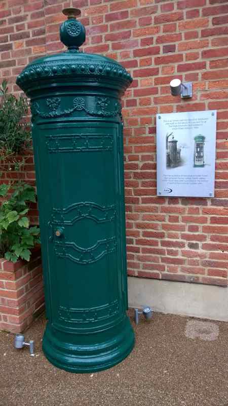
The internal features of the distribution feeder pillar shows large porcelain fuses that protected the low voltage feeder cables – these would have been connected to the bottom of each of the 4 vertical 3-phase units.
➡ For further information about how Lucy Zodion provide control and power distribution products for street lighting applications, please review the Lucy Titan (Cut-outs) and Lucy Trojan (Isolators) ranges of products.
Today, Lucy Zodion are established as the leading manufacturer of feeder pillarsin cast iron, galvanised steel and stainless steel – retractable and pre-wired feeder pillars can be customised to customer specific requirements.
Their Fortress feeder pillars are the market leading range of LV Electrical Distribution Equipment available from stock for next day delivery.
The Lucy range of street lighting cut outs are approved by all UK Distribution Network Operators.
Manufacturers of Cut-outs | Street Lighting | House Service | DNO Utility
THORNE & DERRICK are national distributors LV, MV & HV Cable Installation, Jointing, Substation & Electrical Equipment – we service UK and global businesses involved in cable installations, cable jointing, substation, overhead line and electrical construction at LV, 11kV, 33kV and EHV.
Since 1985, T&D have established an international reputation based on SERVICE | INTEGRITY | TRUST.
Contact us for 3M Electrical, ABB, Alroc, AN Wallis, CATU Electrical, Cembre, Centriforce, CMP, CSD, Elastimold, Ellis Patents, Emtelle, Euromold, Filoform, Furse, Lucy Electric & Zodion, Nexans, Pfisterer, Polypipe, Prysmian, Roxtec, Sicame, WT Henley.
Invitation
Thorne & Derrick invite you to join LinkedIn’s largest LV-HV Electrical Discussion Group : Low & High Voltage Power, Cabling, Jointing & Electricals. Discussion subjects include cable installations, cable jointing, substation, overhead line and electrical construction at LV, 11kV, 33kV and EHV. Network, engage and promote your profile, company or products with over 10,000 influencers.
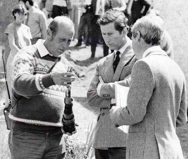
HRH Prince Charles & John Hayes from WPD (Western Power Distribution, UK Utility) discussing high voltage cable on the Isles of Scilly.
THORNE & DERRICK are national distributors LV, MV & HV Cable Installation, Jointing, Substation & Electrical Equipment – we service UK and global businesses involved in cable installations, cable jointing, substation, overhead line and electrical construction at LV, 11kV, 33kV and EHV.
Since 1985, T&D have established an international reputation based on SERVICE | INTEGRITY | TRUST.
Contact us for 3M Electrical, ABB, Alroc, AN Wallis, CATU Electrical, Cembre, Centriforce, CMP, CSD, Elastimold, Ellis Patents, Emtelle, Euromold, Filoform, Furse, Lucy Electric & Zodion, Nexans, Pfisterer, Polypipe, Prysmian, Roxtec, Sicame, WT Henley.
Invitation
Thorne & Derrick invite you to join LinkedIn’s largest LV-HV Electrical Discussion Group : Low & High Voltage Power, Cabling, Jointing & Electricals. Discussion subjects include cable installations, cable jointing, substation, overhead line and electrical construction at LV, 11kV, 33kV and EHV. Network, engage and promote your profile, company or products with over 10,000 influencers.
uploaded by Chris Dodds - Sales & Marekting Manager at Thorne & Derrick International
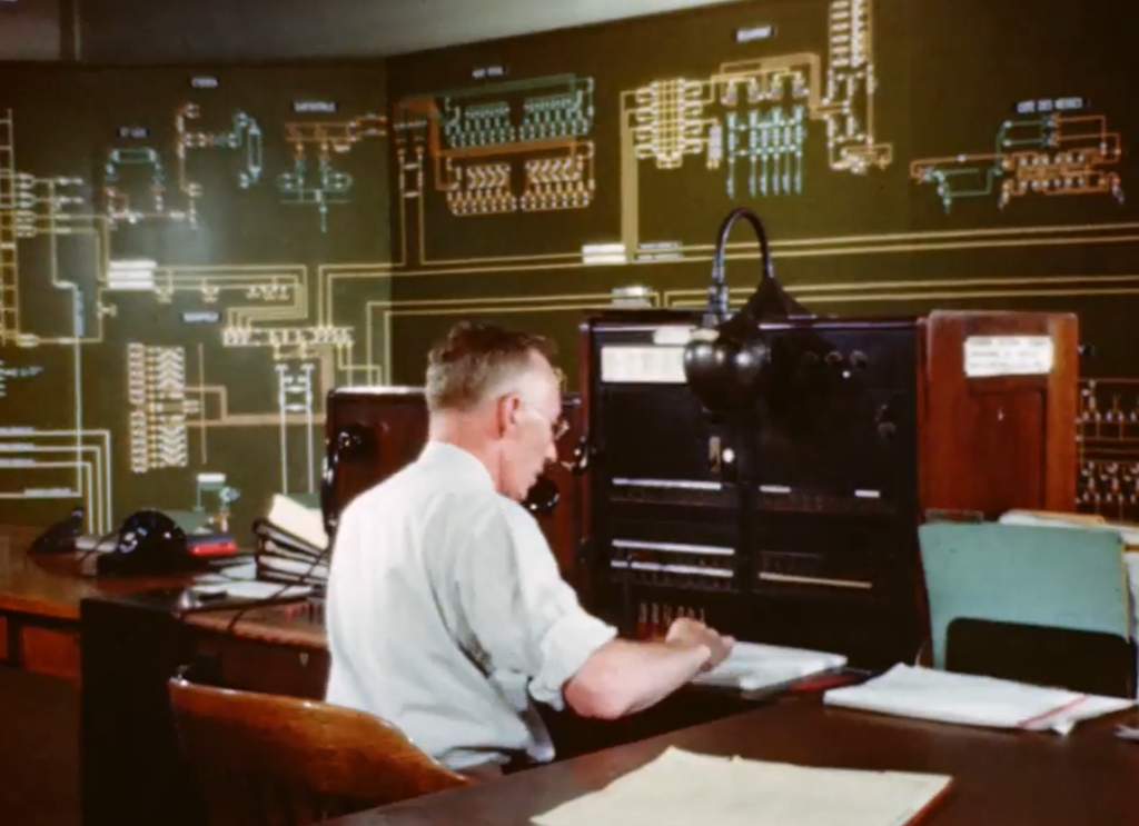
This film is dedicated to the engineers, designers, operators and artisans whose untiring efforts to provide, maintain and improve the distribution of electric power have helped to create our modern way of living.
A film about how hydro-electric power is harnessed, generated, transformed, and distributed by Hydro Quebec. Shots include: building transmission towers and installing cable; designing and building power sub-stations in the Montreal area, to service the city as it grows; an animated sequence showing how a transformer takes high voltage power and converts it into usable units for distribution to communities and businesses; a demonstration of how an emergency repair crew reacts to a power failure.
Thorne & Derrick
THORNE & DERRICK are national distributors LV, MV & HV Cable Installation, Jointing, Substation & Electrical Equipment – we service UK and global businesses involved in cable installations, cable jointing, substation, overhead line and electrical construction at LV, 11kV, 33kV and EHV.
Since 1985, T&D have established an international reputation based on SERVICE | INTEGRITY | TRUST.
Contact us for 3M Electrical, ABB, Alroc, AN Wallis, CATU Electrical, Cembre, Centriforce, CMP, CSD, Elastimold, Ellis Patents, Emtelle, Euromold, Filoform, Furse, Lucy Electric & Zodion, Nexans, Pfisterer, Polypipe, Prysmian, Roxtec, Sicame, WT Henley.
Invitation
Thorne & Derrick invite you to join LinkedIn’s largest LV-HV Electrical Discussion Group : Low & High Voltage Power, Cabling, Jointing & Electricals. Discussion subjects include cable installations, cable jointing, substation, overhead line and electrical construction at LV, 11kV, 33kV and EHV. Network, engage and promote your profile, company or products with over 10,000 influencers.
Uploaded By Chris Dodds – Thorne & Derrick Sales & Marketing Manager
Cable Pulling
In response to a question posed on Voltimum, the leading electrical industry portal, Nexans provided the following answer in reply about the maximum 11kV cable pulling distances between manholes when laying medium/high voltage power cables using cable socks.
T&D, the UK’s leading Cable Pulling & Laying Equipment Supplier, can provide expert technical recommendations and support for all cable pulling and laying projects into both open trench (directly buried) and cable duct.
Important procedural requirements apply to the installation of all MV-HV underground cable pulls irrespective of the method used.
Installation shall be carried out by experienced cable pulling teams with a thorough understanding of the risks specific to the installation methods being used. The installation design, cable pulling equipment and techniques shall be designed to:-
Minimise cable pulling forces on MV-HV cables
Cause no damage to MV-HV cable sheaths during handling/installation into duct or trench
Often cables are snagged or damaged by bedding or backfill materials during the the cable pull process on the cable trench bed – contact us to discuss cable sheath repair products.
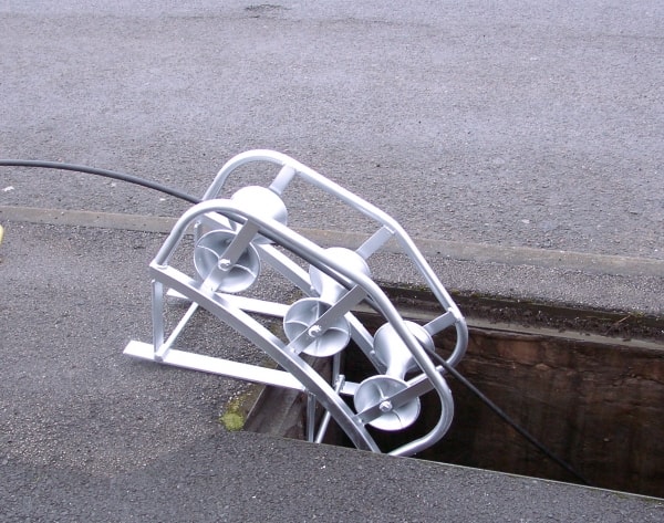
Pictured :Manhole Cable Rollers – care must be taken during high voltage cable pulling not to exceed the maximum pulling force and tension to avoid 11kV cable damage. The cable rollers are designed for placing at the edge of the manhole or pit entrance to ease the cable into position.
Cable Rollers – Order Code ML5
11kV
Question: I’m installing a high voltage 11kV cable in PVC sleeves and I want to introduce manholes on the straight length of the HV power cable route. What will be the maximum distance you would recommend for ease of high voltage cable pulling of the 11kV cable from one manhole to the other?
Answer: This can only be answered properly on a case-to-case basis as it depends a lot on the topography and direction of the proposed 11kV cable pulling route.
This is especially so in urban areas where many bends may be necessary to avoid underground utility cables and pipes such as like sewers, water and gas. If there are no bends, we have still must consider the friction coefficient of the particular cable duct with the 11kV cable.
Of course, cable lubricants can be used as long as they do not harm the sheath material or the duct material – lubrication of the 11kV will reduce the co-efficient of friction of the cable pull between the 11kV cable sheath and inner cable duct wall.
If we speak about 11kV triplex cables, you will get them only in smaller lengths because of the diameter – I suppose 350m on a perfectly straight line shouldn’t be a problem.
But please take into consideration the maximum pulling force, which is: 30N/mm2 of conductor cross-section for aluminium conductors and 50N/mm2 of conductor cross-section for copper conductors.
Going above these forces can damage the 11kV cables and maximum cable pulling vary according to the specification of the medium/high voltage cable.
Maximum permissible pulling tensions for each 11kV/33kV cable type are given below.
These cable pulling tensions must not be exceeded under any circumstances. Efforts should always be made by the cable pulling teams to achieve lower figures by careful setting out of the work and positioning of the MV-HV cable drum.
Maximum Cable Pulling Tensions LV 11kV 33kV Cables (kN)
Conductor Size (sqmm)
95sqmm
150sqmm
185sqmm
240sqmm
300sqmm Al
300sqmm Cu
500sqmm
630sqmm
3-Phase Waveform
2.89
–
7.78
8.67
9.79
–
–
–
11kV PICAS
3.91
–
6.36
–
9.79
–
–
–
11kV 1 Core XLPE
2.85
–
5.55
–
9.0
15.0
–
31.5
11kV 3 Core XLPE
3.91
–
6.36
–
9.79
–
–
–
33kV 1 Core XLPE
–
5.5
–
–
–
–
14.6
18.0
♦ Info: Scottish Power Energy Networks, CAB-15-003: Handling & Installing Cables Up To 33kV
Risk Of Arc Flash & Safe Digging
Civil engineering contractors, jointers and pulling teams must be aware of the arc flash dangers associated with utility excavations when working around buried services including electricity cables. Attention is drawn to the requirements and recommendations contained in Health and Safety Executive guidance notes HSG47 “Avoiding Danger from Underground Services” and HSG185 “Health and Safety in Excavations”. UK DNO’s publish guideline documents about “Safe Digging” and these can be consulted online.
Calvi Electric Company uses Southwire A-Frame truck to facilitate a 1300′ high voltage cable pull through a manhole system. During the video you will observe the high voltage cable being taken up in sections. At the other end of the cable pull a Greenlee Ultra Tugger set up is located, the average for this cable pull was 6 ft per second.
The reason for the sporadic uptake was variable stretch and tension being placed on the cable pulling rope. The total length of the HV cable pull was 1270′. The utility learned that with the ease at which the Southwire A-Frame trucks payoff that it was not necessary to have this large of a crew to handle the consolidation of cable into the trunk of the cable pull. Once set up this cable pull could have been performed with 4 crew members. Additional crew members were necessary and productive in initial manhole set-up, reel set-up and attending to manholes where the wire was being pulled straight through.
Sealing Cable ducts
Where electricity, pilot and telephone cables are installed into electricity cable ducts the utility engineering standard would normally recommend all cable ducts entering substations and buildings to be duct sealed to prevent the ingress of water and gas – this also applies to 33kV, 66kV and 132kV high voltage substation cables where cable transits are required.
Thorne & Derrick distribute an extensive range of Duct Sealing & Cable Transit Systems to protect utility assets and provide flood protection to substations from water entry via unsealed cable ducts and building penetrations.
Thorne & Derrick International distribute the most extensive range of Cable Pulling & Cable Laying Equipmentto enable the installation of low, medium and high voltage power cables into underground trench or duct – products also supplied for fibre optic blowing, subsea trenching, offshore umbilical installations and pulling armoured cables onto cable tray.
Celebrating Charlie & Ella’s Level 4 Sales Executive Apprenticeships At Thorne & Derrick International, we are proud to champion talent development and recognise the dedication required to achieve professional growth. We are therefore delighted to congratulate Charlie Baines and...
Thorne & Derrick will be Exhibiting at Solar & Storage Live UK 2026 at the NEC Birmingham from 22nd–24th September, showcasing our support for HV Cable Accessories, Joints, Terminations, Separable Connectors, Cable Tooling and Grid Connection Products used across...