Cable Cleats, Cable Glands & Cable Lugs For Prysmian FP600S Cables
Published 26 Apr 2019

FP6000S
- uploaded by Chris Dodds – Thorne & Derrick Sales & Marketing Manager
The following article enables the correct specification of cable cleats, glands and lugs for the safe and reliable installation of Prysmian FP600S fire resistant cables without comprising the fire performance of the electrical circuit and integrity of the cable to survive and continue operation in fire conditions.
FP600S Cables
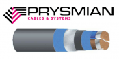
Prysmian FP600S is the ultimate fire resistant, armoured Low Voltage LV cable for power and control of emergency, life safety and fighting systems used in buildings.
Prysmian FP600S is the ultimate fire resistant cable for power and control of emergency, life safety and fighting systems used in buildings.
FP600S has been designed and developed for the most stringent British Standard fire test for cables, BS8491 F120 and meets or exceeds the fire resistance requirements of Category 1,2 and 3 which makes it suitable for power and control circuits as defined in BS8519:2010.
Prysmian fire resistant cable is featured on the LU – Approved Products Register approved by London Underground meeting the criteria for LU 1-085 and is suitable for use in Section 12 (underground and surface) applications.
BS 8519:2010
This British Standard and Code of Practice covers the selection and installation of fire-resistant power and control cable systems for life safety and fire-fighting applications.
BS 8519:2010 replaces BS 7346-6:2005, which is now withdrawn.
High-rise and complex buildings have developed in terms of increased size, height and complexity of active fire protection. This has allowed fire engineered solutions to be developed. These solutions require a high level of performance from the components of the building services, including the electrical supplies.
BS 8519 gives guidance and recommendations on the selection and installation of power and control cable systems. It covers systems that are required to maintain their cable circuit integrity for life safety and fire-fighting applications. It also gives recommendations for electrical system design for such applications, and recommended limits for survival times.
BS 8519 identifies those electrical loads defined as life safety and fire-fighting loads. It lists the factors to be considered by the engineer when selecting and specifying the performance requirements of the electrical distribution system needed to maintain integrity under defined fire conditions for a specified period, referred to as the fire survival time.
BS 8519 makes reference to the recommendations identified in BS 9999, with regard to the design and installation of the LV Low Voltage electrical distribution systems for life safety and fire-fighting equipment.
The British Standard also makes reference to 3 categories of circuits required to maintain their circuit integrity under defined fire conditions for varying fire survival times of 30 min, 60 min and 120 min. Appropriate cable tests are identified for each category derived from applicable British Standards that assess cable performance under conditions of fire as might be expected in an actual fire incident.
This standard aims to ensure that the level of circuit integrity is not compromised by other components of the whole electrical distribution system, including cable glands, terminations, joints and cable support and location systems including stainless steel cable ties.
BS 8519:2010 covers
- The source of supply
- The distribution voltage [high voltage (HV) or low voltage (LV)]
- The appropriate location of the main intake enclosures, HV switchrooms, LV switchrooms, transformer rooms, generator rooms, risers, fire life safety plant rooms and fire-fighting/evacuation lift motor rooms/shafts.

Prysmian FP600S also meets or exceeds low fire hazard requirements of LSOH cable.
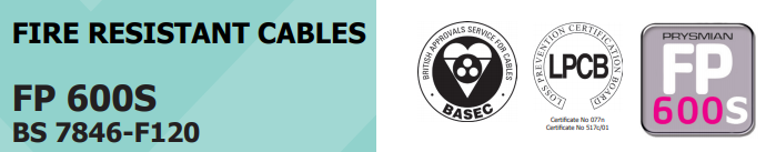
Prysmian FP600S – The Ultimate Fire Resistant Armoured Power Cable
- 600/1000V Cable
- BS7846 F120
- BS8491 120 Minutes
- BS8519 Category 1,2 & 3 Power & Control Circuits
- BASEC Approved Cable
- LPCB Approved Cable
- London Underground Approved LU 1-085A (Previously ‘Section 12’)
Prysmian manufacture a range Fire Resistant cable accessories including cable cleats and cable glands to support the installation of FP600S cables.

Prysmian FP Cables – FP600S Fire Resistant Cables for Emergency & Essential Building Services
Why Degrade Cable Integrity By Installing Underspecified Cable Accessories?
Sub-standard cable accessories are often inadvertently installed forming weak links in many fire resistant cable installations. Plastic cable cleats and “budget” type cable glands only serve to introduce potential “flash-points” into cable circuits whose primary purpose is the safety and protection of people, assets and infrastracture in the event of a fire. For this reason Prysmian only recommend the installation of approved fire resistant glands, cleats and accessories.
The following tables should aid the contractor and specifier to selecting the correct FP cleats, glands and lugs.
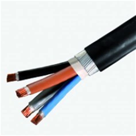
PRYSMIAN FP600S FIRE RESISTANT CABLE – SINGLE CORE CABLES
The following selection table features the recommended cable accessories including claw cleats and cable glands LSF to support and terminate Prysmian FP600S cables – for the termination of the stranded copper conductors into control panels, enclosures, junction boxes and electrical equipment Cembre lugs can be used.
| Nominal Cross Sectional Area (sqmm) | Approximate Overall Diameter (mm) | Approximate Diameter Under Armour (mm) | Nominal Diameter of Armour Wires (mm) | Approximate Cable Weight (kg/km) | Maximum Conductor Resistance at 20ºC (Ω/km) | Short Circuit Rating (1 second) of Conductor kA | Current Rating Three Phase AC Clipped Direct (Amps) | Current Rating Three Phase AC Free Air or Perforated Tray (Amps) | Volt Drop Three Phase AC (mV/A/m) | Recommended Accessories | |
| Claw Cleat Ref Number | Brass Gland Ref Number | ||||||||||
| Three Core Cables | |||||||||||
| 4 | 21 | 15 | 1.25 | 800 | 4.61 | 0.57 | 42 | 44 | 10 | 370CG04 | LSF25CW |
| 6 | 21 | 15 | 1.25 | 820 | 3.08 | 0.86 | 53 | 56 | 6.8 | 370CG04 | LSF25CW |
| 10 | 23 | 17 | 1.25 | 1050 | 1.83 | 1.4 | 73 | 78 | 4.0 | 370CG05 | LSF25CW |
| 16 | 24 | 19 | 1.25 | 1400 | 1.15 | 2.2 | 94 | 99 | 2.5 | 370CG05 | LSF25CW |
| 25 | 29 | 22 | 1.6 | 2000 | 0.727 | 3.6 | 124 | 131 | 1.65 | 370CG06 | LSF32CW |
| 35 | 31 | 24 | 1.6 | 2300 | 0.524 | 5.0 | 154 | 162 | 1.15 | 370CG06 | LSF32CW |
| 50 | 32 | 25 | 1.6 | 2800 | 0.387 | 7.1 | 187 | 197 | 0.87 | 370CG07 | LSF32CW |
| 70 | 36 | 29 | 1.6 | 3600 | 0.268 | 10.0 | 238 | 251 | 0.60 | 370CG07 | LSF40CW |
| 95 | 40 | 32 | 2.0 | 4500 | 0.193 | 13.6 | 289 | 304 | 0.45 | 370CG08 | LSF50SCW |
| 120 | 43 | 35 | 2.0 | 5400 | 0.153 | 17.2 | 335 | 353 | 0.37 | 370CG08 | LSF50SCW |
| 150 | 48 | 39 | 2.5 | 6900 | 0.124 | 21.4 | 386 | 406 | 0.30 | 370CG09 | LSF50CW |
| 185 | 52 | 43 | 2.5 | 8200 | 0.0991 | 26.5 | 441 | 463 | 0.26 | 370CG09 | LSF63CW |
| 240 | 57 | 47 | 2.5 | 10100 | 0.0754 | 34.3 | 520 | 546 | 0.21 | 370CG09 | LSF63CW |
| 300 | 62 | 52 | 2.5 | 12200 | 0.0601 | 42.9 | 599 | 628 | 0.185 | 370CG12 | LSF63CW |
| 400 | 69 | 58 | 2.5 | 15000 | 0.0470 | 57.2 | 673 | 728 | 0.165 | 370CG13 | LSF75CW |
| Four Core Cables | |||||||||||
| 4 | 21 | 15 | 1.25 | 800 | 4.61 | 0.57 | 42 | 44 | 10 | 370CG04 | LSF25CW |
| 6 | 23 | 17 | 1.25 | 950 | 3.08 | 0.86 | 53 | 56 | 6.8 | 370CG05 | LSF25CW |
| 10 | 24 | 19 | 1.25 | 1200 | 1.83 | 1.4 | 73 | 78 | 4.0 | 370CG05 | LSF25CW |
| 16 | 27 | 20 | 1.25 | 1600 | 1.15 | 2.2 | 94 | 99 | 2.5 | 370CG06 | N/A |
| 25 | 32 | 24 | 1.6 | 2400 | 0.727 | 3.6 | 124 | 131 | 1.65 | 370CG07 | LSF32CW |
| 35 | 35 | 27 | 1.6 | 2800 | 0.524 | 5.0 | 154 | 162 | 1.15 | 370CG07 | LSF40CW |
| 50 | 36 | 29 | 1.6 | 3200 | 0.387 | 7.1 | 187 | 197 | 0.87 | 370CG07 | LSF40CW |
| 70 | 41 | 32 | 1.6 | 4500 | 0.268 | 10.0 | 238 | 251 | 0.60 | 370CG08 | LSF50SCW |
| 95 | 44 | 36 | 2.0 | 5700 | 0.193 | 13.6 | 289 | 304 | 0.45 | 370CG08 | LSF50SCW |
| 120 | 49 | 40 | 2.0 | 7300 | 0.153 | 17.2 | 335 | 353 | 0.37 | 370CG09 | LSF50CW |
| 150 | 55 | 44 | 2.5 | 8600 | 0.124 | 21.4 | 386 | 406 | 0.30 | 370CG10 | LSF63CW |
| 185 | 59 | 48 | 2.5 | 10500 | 0.0991 | 26.5 | 441 | 463 | 0.26 | 370CG11 | LSF63CW |
| 240 | 64 | 54 | 2.5 | 12900 | 0.0754 | 34.3 | 520 | 546 | 0.21 | 370CG12 | LSF63CW |
| 300 | 70 | 59 | 2.5 | 15500 | 0.0601 | 42.9 | 599 | 628 | 0.185 | 370CG14 | LSF75CW |
| 400 | 79 | 66 | 3.15 | 20100 | 0.0470 | 57.2 | 673 | 728 | 0.165 | 370CG15 | LSF85CW |
| Five Core Cables | |||||||||||
| 4 | 22 | 17 | 1.25 | 900 | 4.61 | 0.6 | 42 | 44 | 10 | 370CG05 | LSF25CW |
| 6 | 24 | 18 | 1.25 | 1070 | 3.08 | 0.9 | 53 | 56 | 6.8 | 370CG05 | LSF25CW |
| 10 | 27 | 21 | 1.25 | 1390 | 1.83 | 1.4 | 73 | 78 | 4.0 | 370CG06 | N/A |
| 16 | 30 | 23 | 1.6 | 1900 | 1.15 | 2.2 | 94 | 99 | 2.5 | 370CG06 | LSF32CW |
| 25 | 34 | 26 | 1.6 | 2500 | 0.727 | 3.6 | 124 | 131 | 1.65 | 370CG07 | LSF40CW |
| 35 | 37 | 29 | 1.6 | 3100 | 0.524 | 5.0 | 154 | 162 | 1.15 | 370CG07 | LSF40CW |
| Nominal Cross Sectional Area (sqmm) | Approximate Overall Diameter (mm) | Approximate Diameter Under Armour (mm) | Nominal Diameter of Armour Wires (mm) | Approximate Cable Weight (kg/km) | Maximum Conductor Resistance at 20ºC (Ω/km) | Current Rating DC or Single Phase AC Clipped Direct (Amps) | Current Rating DC or Single Phase AC Free Air (Amps) | Volt Drop DC (mV/A/m) | Volt Drop Single Phase AC (mV/A/m) | Recommended Accessories | |
| Claw Cleat Ref Number | Brass Gland Ref Number | ||||||||||
| Two Core Cables | |||||||||||
| 4 | 21 | 15 | 1.25 | 800 | 4.61 | 49 | 52 | 12 | 12 | 370CG04 | LSF25CW |
| 6 | 21 | 15 | 1.25 | 800 | 3.08 | 62 | 66 | 7.9 | 7.9 | 370CG04 | LSF25CW |
| 10 | 22 | 16 | 1.25 | 800 | 1.83 | 85 | 90 | 4.7 | 4.7 | 370CG05 | LSF25CW |
| 16 | 23 | 17 | 1.25 | 1000 | 1.15 | 110 | 115 | 2.9 | 2.9 | 370CG05 | LSF25CW |
| 25 | 26 | 20 | 1.25 | 1300 | 0.727 | 146 | 152 | 1.85 | 1.9 | 370CG06 | N/A |
| 35 | 30 | 23 | 1.6 | 1800 | 0.524 | 180 | 188 | 1.35 | 1.35 | 370CG06 | LSF32CW |
| 50 | 31 | 24 | 1.6 | 2200 | 0.387 | 219 | 228 | 0.98 | 1.00 | 370CG06 | LSF32CW |
| 70 | 33 | 26 | 1.6 | 2600 | 0.268 | 279 | 291 | 0.67 | 0.69 | 370CG07 | LSF32CW |
| 95 | 35 | 27 | 2.0 | 3400 | 0.193 | 338 | 354 | 0.49 | 0.52 | 370CG07 | LSF40CW |
| 120 | 39 | 30 | 2.0 | 4100 | 0.153 | 392 | 410 | 0.39 | 0.42 | 370CG08 | LSF50SCW |
| 150 | 42 | 33 | 2.0 | 4700 | 0.124 | 451 | 472 | 0.31 | 0.35 | 370CG08 | LSF50SCW |
| 185 | 46 | 36 | 2.5 | 6100 | 0.0991 | 515 | 539 | 0.25 | 0.29 | 370CG09 | LSF50CW |
| 240 | 51 | 41 | 2.5 | 7500 | 0.0754 | 607 | 636 | 0.195 | 0.24 | 370CG09 | LSF50CW |
| 300 | 56 | 45 | 2.5 | 9000 | 0.0601 | 698 | 732 | 0.155 | 0.21 | 370CG10 | LSF63CW |
| 400 | 61 | 50 | 2.5 | 11000 | 0.0470 | 787 | 847 | 0.120 | 0.19 | 370CG11 | LSF63CW |
LV Cable Joints (Low Voltage Cables)
Thorne & Derrick stock and distribute LV Joints in Cold Shrink, Heat Shrink or Resin Cast technologies – multicore and multi-pair cable joints are available for immediate backfill and energisation of Low Voltage power, control and instrumentation cables 600V/1000V 3.3kV.
Complete range of LV Cable Accessories ➡
Cable Breakouts | Cable Caps | Cable Lugs | Cable Cleats | Cable Trough | Cable Duct | Feeder Pillars | for 11kV/33kV/66kV networks see MV HV Joints & Terminations

Pfisterer | Nexans Euromold | Prysmian | Cable Joints & Terminations MV HV
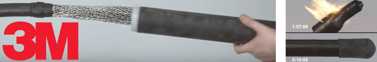
Cold Shrink by 3M | Joints | Abandonment | Terminations | Low Voltage LV Cables
Further Reading
-
 Prysmian FP600S Fire Resistant Power Cable – BS8491 F120 Armoured Cables
Size: 156.65 KB
Prysmian FP600S Fire Resistant Power Cable – BS8491 F120 Armoured Cables
Size: 156.65 KB
-
Prysmian FP600S Fire Resistant Power Cable – BS8491 F120 Armoured Cables – Component Selector
Size: 213.97 KB