

Blog
Ellis Patents Pegasus Cable Hangers For Rail Cable Support
March 15th, 2019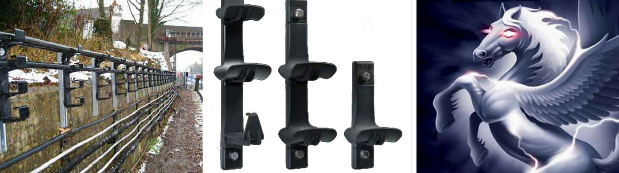
-
uploaded by - Chris Dodds Thorne & Derrick Sales & Marketing Manager
Cable Hangers
Ellis Patents are committed to driving technology forward and improving product performance to prolong the lifespan of their cable cleats and cable hangers while improving overall rail industry safety.
As a result, Ellis Patents have now launched Pegasus – a modular cable hanging system that is stronger, lighter and more flexible than traditional galvanised steel type hangers.
Ellis Patents J Type rail cable hangers are installed throughout the global rail industry – this includes both J type cable hangers made from either galvanised steel or nylon to support rail cable runs.
Trackside cable installations and supporting infrastructure must demonstrate the ability to provide reliable service in harsh operating conditions.
Fumes and brake dust are a typical rail challenge – particles of brake pads and discs from trains can lead to “pitting” corrosion of metallic surfaces.
Once exposed to moisture, dew or rain the corrosion process is accelerated.
Pressure waves, moisture and dirt combine to confront underground rail infrastructure with considerable material and design specification challenges for cable supports and hanging systems on LV (Low Voltage), MV (Medium Voltage) and HV (High Voltage) power systems.
Corrosion resistant nylon cable hangers are specified on the rail network for excellent environmental performance – this includes power, signal and telecoms (S&T) trackside and tunnel cable support where the cable hangers are exposed to UV, weathering and diesel fuels on non-electrified rail networks.
Ellis Patents Pegasus cable hangers withstand temperature, humidity and aggressive exhaust gases experienced on underground rail systems.
The curved saddle shape design of Pegasus cable hangers prevents cable damage caused by sharp edge contact.
Available in a range of sizes the cable hangers accommodate cables with outside diameters from 50mm-100mm and up to 6 cable runs per hanger.
With the recent launch of Pegasus non-metallic cable hangers by Ellis Patents, electrical safety can be improved and product life cycle extended.
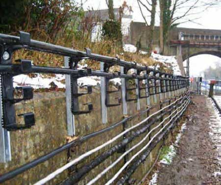
Pictured : Cable Hanger – “J” Hangers 4 Way Type Supporting Trackside Power Cables. Plastic type cable hangers formally manufactured by Melcroft have increasingly been replaced by a galvanised type J hanger. The pictured Melcroft cable hangers below are now obsolete from manufacturing and have been replaced by either Ellis Patents galvanised steel or non-metallic nylon cable hanger types.
Why Nylon For Rail Cables ?
Ellis Patents Pegasus cable hangers are manufactured from high strength nylon especially formulated to meet the requirements of London Underground 1-085 specification.
Independent testing is carried out to prove conformance to the 1-085 standard including toxicity, limited oxygen and smoke emission.
The extruded aluminium spine is marine grade and with a shaped profile designed to provide maximum strength for supporting rail cables. The cable hangers are non-metallic eliminating corrosion and the consequent mechanical degradation to the hanger caused by exposure to pollutants whether trackside or at increased concentration levels in tunnels.
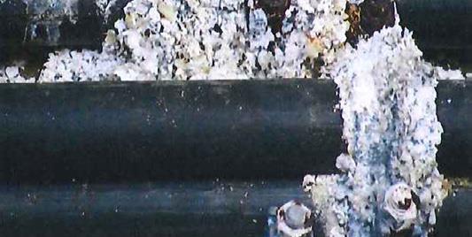
Pictured : Tunnel Wall Cabling – the following photo highlights the extent of tunnel dust accumulation in an underground rail tunnel. Atmospheric corrosion to steel can cause increased maintenance work and necessitate more frequent routine inspection by corrosion engineers. Further corrosion causes include the leaking of chemicals in the rocks or earth surrounding the tunnel and seepage of water from roads or rivers into tunnel walls.
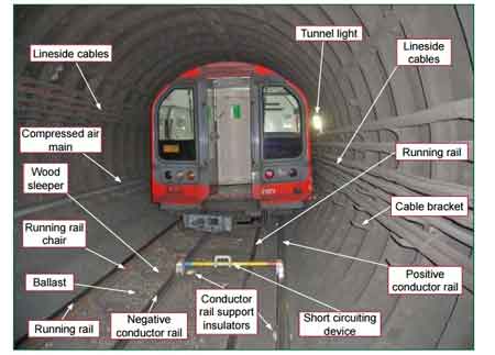
Image : RAIB
Fire Safety Performance Of Underground Rail Materials – 1-085
Following the disastrous and tragic Kings Cross Station fire in 1987, London Underground began to specify the use of materials which do not give off smoke or toxic fumes in the construction and maintenance of the underground rail network – this is now controlled by LU London Underground Standard 1-085.
Ellis Patents Pegasus cable hangers are manufactured from a high strength, low smoke and fume, zero halogen polymer – they are LU 1-085 registered.

Ellis Patents J Type Galvanised Steel Cable Hangers – traditional galvanised steel hangers, commonly referred to as J hangers were designed to withstand the operating conditions on above and underground rail networks while supporting LV MV HV rail cables.
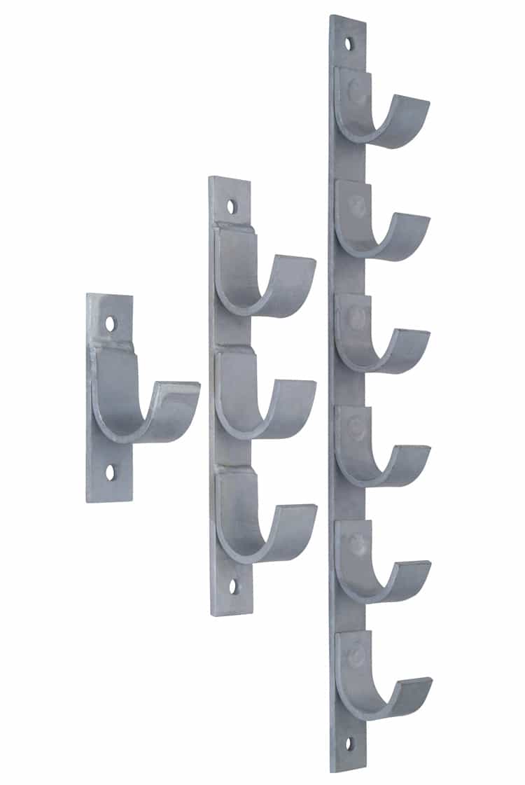
Launched at Railtex 2015, the Ellis Patents Pegasus range of nylon cable hangers are LU London  Underground approved for above ground and sub-surface cable support applications.
“After 2 years in development, I’m confident that our re-invention of the cable hanger system means that we have a new product on our hands that will quickly become one of our most successful,” Richard Shaw (MD Ellis Patents).
T&D asked Paul Nolan (Ellis Patents UK Sales Director) why Pegasus Cable Hangers are set to become the standard specification for cable support in the UK and global rail industry.
Paul provided 5 powerful reasons :
- Lightweight – 50% lighter than steel, single person installation
- Modular – versatile for new cable project installations
- Corrosion Resistant – non-metallic but high strength
- Maintenance Free – enhanced service life compared to steel
- Stronger Than Steel – 40kg safe working load per cable hanger
Modular Cable Hangers – Trackside & Tunnel
The intelligent and flexible design of Pegasus cable hangers enables Electrical Design Engineers working on Rail S&T and Power distribution designs to produce the optimum cable layout without restriction by the availability of suitable cable supports.
Ellis Patents can produce CAD files on request to allow for the production of accurate drawings. Ellis Patents Pegasus cable hangers can be used to support 11kV and 22kV feeder cables and 25kV traction substation cables in HV cable tunnels or trackside.
Ellis Patents cable hanger systems are designed to overcome the challenges faced installing today’s modern rail cables in increasingly complex projects.

Cable Hangers – Non Metallic Cable Hanging Systems (LV MV HV Cable) – Dimensions
Ellis Patents Pegasus LUL Approved Cable Hangers

Furthermore, as the drive to electrify the UK rail network advances consideration is increasingly being given to non-metallic trackside equipment. Electrocution hazards are eliminated by non-conductive cable hangers. Metallic infrastructure and equipment is prone to corrosion, denting and generating potential electrocution shocks due to conductivity.

LV, MV & HV Jointing, Earthing, Substation & Electrical Eqpt
Thorne & Derrick International are specialist distributors of LV, MV & HV Cable Installation, Jointing, Duct Sealing, Substation & Electrical Equipment – servicing UK and global businesses involved in cable installations, cable jointing, substation, overhead line and electrical construction at LV, 11kV, 33kV and EHV.
THORNE & DERRICK Product Categories: Duct Seals | Cable Cleats | Cable Glands | Electrical Safety | Arc Flash Protection | Cable Jointing Tools | Cable Pulling | Earthing | Feeder Pillars | Cable Joints LV | Joints & Terminations MV HV

The Importance of Cable Cleats on Multi-Core Cables – Video
March 15th, 2019
-
uploaded by Chris Dodds - Sales & Marketing Manager (Thorne & Derrick International)
Ellis Patents Cable Cleats
Front Line Defence Against Short Circuits
The below video produced by Ellis Patents shows the catastrophic outcome when multi-core cables attached to cable ladder using cable ties only are subjected to short circuit cable fault. Depending on fault levels cable cleats should be used to secure LV MV HV cables and to provide short circuit protection against disastrous cable faults, this includes the cable cleating of multi-core power cables.
Cable cleats are vital – cable ties alone cannot contain certain short circuit faults.
Depending upon the fault level rating of low and high voltage power cable installations cable cleats are essential short circuit protection devices.

Ellis Patents are global leaders in the innovation and manufacture of nylon, aluminium and stainless steel cable cleats – EP cleats and cable hangers satisfy the operational requirements of the construction, oil, gas, rail, utilities, wind energy and power generation industries.
Holding Power is Ellis Patents guarantee that EP Cable Cleats will contain dangerous short circuit forces – protecting your people, power and plant.
Vital Short Circuit Protection
with Cable Cleats
Ellis Patents are a leading voice in the campaign to have cable cleats reclassified as short-circuit protection devices. A move that would mean cable cleats would be placed on a parallel with fuses and circuit breakers.
“This reclassification makes absolute sense. In the event of a cable fault, the forces between cables reach their peak in the first quarter cycle, which is the point that cable cleats earn their crust. In contrast, circuit breakers typically interrupt the fault after 3 or even 5 cycles by which time, if the cable cleats are underspecified, the cables will no longer be secure, but will be putting vital electrical installations and lives at unnecessary risk,” says Paul Nolan (former) UK Sales Manager, Ellis Patents.
LV, MV & HV Jointing, Earthing, Substation & Electrical Eqpt
Thorne & Derrick International are specialist distributors of LV, MV & HV Cable Installation, Jointing, Duct Sealing, Substation & Electrical Equipment – servicing UK and global businesses involved in cable installations, cable jointing, substation, overhead line and electrical construction at LV, 11kV, 33kV and EHV.
THORNE & DERRICK Product Categories: Duct Seals | Cable Cleats | Cable Glands | Electrical Safety | Arc Flash Protection | Cable Jointing Tools | Cable Pulling | Earthing | Feeder Pillars | Cable Joints LV | Joints & Terminations MV HV
Understanding the Importance of Cable Cleats in Offshore Industries
March 15th, 2019
LV MV HV Marine Offshore & Electrical Equipment DNV
-
uploaded by Chris Dodds - Sales & Marketing Manager (Thorne & Derrick International)
Offshore Cable Cleats
By its very nature, offshore, and other oil exploration work is fraught with danger, which is why so many millions of pounds are spent ensuring the very highest standards of health and safety are met.
Therefore, it would seem extremely remiss if a significant aspect of this type of installation was frequently neglected – yet according to one of the world’s leading cable cleat manufacturers there is.
According to Ellis Patents, the key issue surrounding cable cleats and their use in this type of marine or offshore environment is that their importance is frequently underestimated.
Therefore, instead of being treated as a vital element of any cable management installation they are frequently lumped in with the electrical bulk sundries.
What this means in practice is that even if suitable cable support products are specified, they are still seen as fair game for cost-cutting when it comes to companies seeking to keep within tight budgets. And this practice, if allowed to continue unchecked, could lead to the wholly unnecessary loss of a life.
There is absolutely no doubt that by eradicating this practice this danger can be drastically reduced, but the big picture also needs to be addressed to ensure consistence practice across the board.
The only way of achieving this is by educating contractors, specifiers – in fact, the offshore industry as a whole – as to the true importance of cable cleats. And to do this, we need to go back to basics.
In a nutshell, for any electrical installation to be deemed safe, cables need to be restrained in a manner that can withstand the forces they generate, including those generated during a short circuit.
Short Circuit Cable Protection
Using Cable Cleats
The Video produced by Ellis Patents provides compelling evidence of the need to ensure all cables are adequately supported and retained to cable containment to protect against the devastating effects of short circuit faults: 118kA Short Circuit Fault Current | 0.1 Seconds Duration | 480V Low Voltage Cables.
And this is exactly what cable cleats are designed to do. Without them, the dangers are obvious. Costly damage to cables and/or cable management systems, plus the risk to life posed by incorrectly or poorly restrained live cables.
One of the major contributing factors behind the current, and somewhat confused situation, is that although cable cleats are recognised by industry regulators, having their own European standard (EN50368) and an International one (IEC61914 Ed. 1) expected soon, these are simply advisory guidelines rather than obligatory regulations.
With no golden guideline to follow, the market is very much manufacturer driven.
Different companies manufacture to different standards and so the market is something of a mish-mash of products of varying quality.
Add to this the facts that the majority of cleats are manufactured as add-ons by companies that specialise in other areas, and that some of today’s cleats are not even short-circuit tested prior to being put into production, and it is easy to see why their importance isn’t fully understood, let alone appreciated.
In the long-term the whole situation needs to be resolved through a process of education and agreement involving manufacturers, regulators, specifiers, contractors and installers.
But, what of the short-term?
What should be being done in order to ensure corners are not cut and safety sacrificed when it comes to cable cleats? To answer this, installations need to be split into two categories – new and old.
In the case of new installations, the process needs to begin during the design stages.
Ideally, this would commence with the forces between cables being calculated so as to ascertain the type and strength of the cleat required.
A number of other factors then need to be taken into account, including physical performance, mounting surface and the environment in which the installation will be situated. Only when this has all been tested and measured can the designer be confident of specifying the correct offshore cable cleat for the installation.
Old Cable Cleat Installations
Old installations meanwhile pose a completely different set of problems. Many will have been installed before the introduction of any related standards, while those that came later may still not be suitable.
Therefore, it’s advisable to review all cabling in such installations to ensure it is safely restrained in relation to today’s requirements.
Understanding the need for cleats and the processes involved in their correct specification is though only half the story.
Cleats themselves come in a variety of sizes and types and it’s important to understand this variation in order to ensure they are correctly chosen.
And perhaps the simplest way of doing this is by ensuring the product comes with suitable third party certification that it can withstand the forces it claims to – this would come in the form of a short circuit testing certificate.

Wooden Cable Cleats – originally cables were supported with cleats made from wood prior to the development of metallic cable cleating products
Cable Protection
Additionally, levels of cable protection can be enhanced by selecting products with Cat 2 passes rather than Cat 1. What this means, is that the cable would be guaranteed to still be intact and operable after a short circuit, as opposed to just the cable cleat.
If you look at this prescribed course of action from a budgeting point of view, it is fair to say that certain initial costs would be increased.
But if you consider the kind of sums involved, in terms of time, materials and manpower, in replacing an entire cable management system due to a short circuit occurring and causing irreparable damage it’s easy to see the point of the additional expense.
And, finally, when you also take in account the effects of improving health and safety levels, there surely can be no argument against ensuring correct cleating practice.
The below video clip demonstrates the short-circuit withstand capability of Ellis Patents Emperor Trefoil Cleats.
A short-circuit of 59kA RMS (118kA peak) is subject to the three-phase cable arrangement for a period of 0.1 seconds, showing the power cables being forced apart by the physical forces present under such fault conditions and demonstrating the need for correctly specified cable cleats in offshore industries.
LV, MV & HV Jointing, Earthing, Substation & Electrical Eqpt
Thorne & Derrick International are specialist distributors of LV, MV & HV Cable Installation, Jointing, Duct Sealing, Substation & Electrical Equipment – servicing UK and global businesses involved in cable installations, cable jointing, substation, overhead line and electrical construction at LV, 11kV, 33kV and EHV.
THORNE & DERRICK Product Categories: Duct Seals | Cable Cleats | Cable Glands | Electrical Safety | Arc Flash Protection | Cable Jointing Tools | Cable Pulling | Earthing | Feeder Pillars | Cable Joints LV | Joints & Terminations MV HV
Cable Cleats – Q&A Session With Ellis Patents
March 15th, 2019
-
uploaded by Chris Dodds - Thorne & Derrick Sales/Marketing Manager
Ellis Patents Cable Cleats
Thorne & Derrick Internatonal, based in the UK, are an Ellis Patents distributor for their market-leading and innovative range of cable cleats manufactured in the UK.
Ellis Patents are global leaders in the innovation and manufacture of nylon cable cleats, aluminium cable cleats and stainless steel cable cleats – Ellis satisfy the operational requirements of the construction, oil, gas, rail, utilities, wind energy and power generation industries.
Holding Power is Ellis Patents guarantee that EP Cable Cleats will contain dangerous short circuit forces – protecting your people, power and plant.
Without Fail – specify Ellis cable cleats for short-circuit protection of LV MV HV cables.
Q1 – Is there a recognised cable cleat standard to guide the electrical industry in the selection and specification of cable cleats?
A1 – International Cable Cleat Standard IEC61914:2009 covers the testing and performance of short circuit cable cleats for low and high voltage cable support.

IEC61914 – Calculating Short Circuit Forces To Specify Compliant Cable Cleats
Q2 – What are the key factors in determining the correct cable cleat selection?
A2 – Environment, mounting structure, cable specification, cable configuration, peak short circuit fault level and outside cable diameter – this will enable effective specification of the cable cleat plus recommended cleat spacing.
Q3 – Can the correct cable cleat be specified based only upon the cross sectional area of the cable conductors?
A3 – No, the cable cleat retains around the outside diameter of the cable – see A2.

Q4 – I am confused but impressed by the level of customer choice with respect to triplex cable cleats. Why are there so many Ellis cleat options?
A4 – It is important that when selecting cable cleats for high voltage triplex cables that the cable cleats can handle the anticipated fault currents especially at working voltages of 11kV/33kV – also, different DNO’s specify different cleats.
➡ Triplex Cleats – Selection Guide for Cleating 11kV BS7870 Part 4.10 Cables

11kV Triplex High Voltage Cable Cleat Surround (MV-HV Cables)
Q5 – In order to retain high voltage power cables we require cable cleats with high fault rating but are concerned about potential outer cable sheath damage to “soft-sheathed” type power cables with EPR insulation. Typical oil rig application.
A5 – Specify and install Ellis Patents cable cleats with cushion liners – Ellis Emperor, Ellis Vulcan and Ellis Atlas cable cleats are all available with liners.

Ellis Patents Vulcan, Atlas & Emperor Cable Cleats
Q6 – Why do Ellis Patents manufacture cable cleats with liners?
A6 – Ellis cable cleats with built-in liners provide effective cushioning to cables during short circuit conditions.
Q7 – Can Ellis Patents support their technical specification with Video short circuit testing?
A7 – Yes, watch these Ellis Patents Videos on YouTube
Q8 – Why are cable cleats manufactured in stainless steel and aluminium?
A8 – Stainless steel and aluminium cable cleats are both non-magnetic and unaffected by magnetic fields surrounding low and high voltage power cables. Cables fixed with cable cleats made from magnetic materials would cause localised heating of cleated cables by the effects of induction.
Q9 – What is galvanic corrosion and how may it impact on cable cleat installations?
A9 – Read our cable cleats and galvanic corrosion Blog
Q10 – Can Ellis Patents provide technical advice on cable cleat considerations for multi-core cable installations?
A10 – Of course, here goes. As manufacturers of cable cleats, Ellis Patents are frequently asked for advice on the correct method of securing multi-core power cables.
We are not aware of any published data, which indicates any particular fixing method but custom and practice suggests that most users presume that any forces on the conductors, which arise in the event of a short circuit, will be restrained within the cable jacket and therefore cable cleats are not required.
The mechanisms within a multi-core cable, which help restrain the conductors in the event of a short circuit include:
1. The outer extruded jacket
2. The helical winding of the cores
3. Steel wire or other type of armour if present
In order to be able to provide meaningful advice Ellis Patents undertook a series of short circuit tests using 3 core, copper conductor, multi-core cables from various cable manufacturers.
Both armoured and unarmoured cables were tested across a variety of conductor sizes but because of the number of manufacturers and the variety of cable types and methods of construction available, it was not feasible to carry out exhaustive tests.
The results of the tests were varied but clearly showed that it is unsafe to presume that the forces between the conductors will always be restrained within the jacket of the cable, whether or not the cable is armoured or tightly helically wound.
Ellis Patents conclusion is that, unless the relevant cable manufacturer can give assurances regarding the performance of their specific cable at the anticipated fault level, fault rated cable cleats provide the safest option for securing multi-core cables.
Ellis Patents Ltd carry out a regular schedule of short-circuit tests.
If you are planning a project and would like certainty regarding the cable fixings for your installation (whether single or multi-core cables are included in the design) T&D and Ellis Patents would be interested to conduct a bespoke test, on your behalf, within our regular programme of work.
LV, MV & HV Jointing, Earthing, Substation & Electrical Eqpt
Thorne & Derrick International are specialist distributors of LV, MV & HV Cable Installation, Jointing, Duct Sealing, Substation & Electrical Equipment – servicing UK and global businesses involved in cable installations, cable jointing, substation, overhead line and electrical construction at LV, 11kV, 33kV and EHV.
THORNE & DERRICK Product Categories: Duct Seals | Cable Cleats | Cable Glands | Electrical Safety | Arc Flash Protection | Cable Jointing Tools | Cable Pulling | Earthing | Feeder Pillars | Cable Joints LV | Joints & Terminations MV HV
Ellis Patents Centaur Cable Saddles Support London Power Tunnel 400kV Cables
March 15th, 2019
-
uploaded by - Chris Dodds Thorne & Derrick Sales/Marketing Manager
Ellis Patents Centaur Cable Saddles
Ellis Patents, the world’s leading cable manufacturer of cable cleats, has secured a £1.5million order for its Centaur cable saddles and accessories to secure high voltage cables in National Grid’s London Power Tunnels project.
Cable cleats, saddles and J type hangers can be custom manufactured to accommodate extra high voltage (EHV) power cables and steelwork support fixing.

National Grid London Power Tunnel
The project will help ensure Londoners continue to enjoy safe and reliable electricity supplies. When complete there will be over 30km of tunnels carrying high voltage cables between substations in Wimbledon, Hackney, Willesden and St John’s Wood.
Ellis’ Centaur cable saddles, which were developed specifically for use with high voltage cables, were specified by Sϋdkabel, the German manufacturers of the cables being installed in the National Grid tunnels. The order was secured on the back of recent work for National Grid and the fact Ellis Patents was able to prove the suitability and safety of its Centaur product for the project’s specification.

High Voltage Cable Cleats (HV EHV 132kV 275kV 400kV Cables) – Ellis Patents Centaur
Richard Shaw, Managing Director of Ellis, said: “This order has given us dual cause for celebration. Firstly, it’s the largest the company has ever won and secondly it demonstrates why we place so much emphasis on research and development.”
Back in 2008 Ellis launched Centaur; a heavy-duty extruded aluminium saddle cleat that had been designed and developed in-house in response to a serious safety issue surrounding the restraint of high voltage cables up to 400kV with a diameter range of 100 to 160mm.

Ellis Patents Centaur Saddle – Hinged Aluminium Overstrap
“At the time neither the British nor European Standards took into account cleats on cables of this size,” explained Richard. “This meant those specifying for such jobs were very much in the hands of the cable cleat manufacturers, who in most cases simply provided warranties for their cable support products.”
“The problem with this was that none of the products available had been short circuit tested, and so the warranties were based purely on calculations and mechanical tests. As such there was no proof the saddle cleats being used would withstand the most testing elements of the job they’d been bought for.”

Ellis Patent Centaur Cable Saddles – Tunnel Cables
Prior to launch, Ellis put the new product through the most rigorous of testing procedures.
Using cable manufactured by ABB in Sweden, the company shipped the Centaur cable saddles and ABB cable to the Netherlands where they were tested to 163 kA peak and 63 kA RMS for one second, in both 3 phase and phase to phase fault scenarios.
“We invested well over £100,000 in designing, developing, testing and bringing Centaur to market,” added Richard. “At the time this was the largest amount we’d ever invested in one new product, but we did so with confidence that it had the potential to solve a major safety issue and fill a gap in a growing market sector – something that has since been proved wholly correct.”
Ellis Patents Centaur Cable Saddle Specifications
 The following selection table provides information to enable the specification or purchase of the correct cable cleat – contact Thorne & Derrick for further technical information, installation advice, samples or to place an order.
| Part Number | Cable Range Dia. | Length Of Cable Saddle |
| Ellis Patents CS100-112/400 | 100mm – 112mm | 400mm |
| Ellis Patents CS108-122/400 | 108mm – 122mm | 400mm |
| Ellis Patents CS120-132/400 | 120mm – 132mm | 400mm |
| Ellis Patents CS128-142/400 | 128mm – 142mm | 400mm |
| Ellis Patents CS140-152/400 | 140mm – 152mm | 400mm |
| Ellis Patents CS148-162/400 | 148mm – 162mm | 400mm |
| Ellis Patents CS100-112/600 | 100mm – 112mm | 600mm |
| Ellis Patents CS108-122/600 | 108mm – 122mm | 600mm |
| Ellis Patents CS120-132/600 | 120mm – 132mm | 600mm |
| Ellis Patents CS128-142/600 | 128mm – 142mm | 600mm |
| Ellis Patents CS140-152/600 | 140mm – 152mm | 600mm |
| Ellis Patents CS148-162/600 | 148mm – 162mm | 600mm |
| Ellis Patents CS100-112/800 | 100mm – 112mm | 800mm |
| Ellis Patents CS108-122/800 | 108mm – 122mm | 800mm |
| Ellis Patents CS120-132/800 | 120mm – 132mm | 800mm |
| Ellis Patents CS128-142/800 | 128mm – 142mm | 800mm |
| Ellis Patents CS140-152/800 | 140mm – 152mm | 800mm |
| Ellis Patents CS148-162/800 | 148mm – 162mm | 800mm |
Ellis Patents Centaur cable saddles consists of an extruded and pressed aluminium saddle and a hinged aluminium overstrap, which incorporates a Low Smoke Zero Halogen Polymeric liner. The curvature of the cable saddle accommodates the thermal expansion of the cable and the ends of the saddle are flared so that the cable never comes into contact with a sharp edge under any circumstances.
INSTALLING CABLE CLEATS
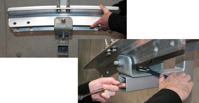
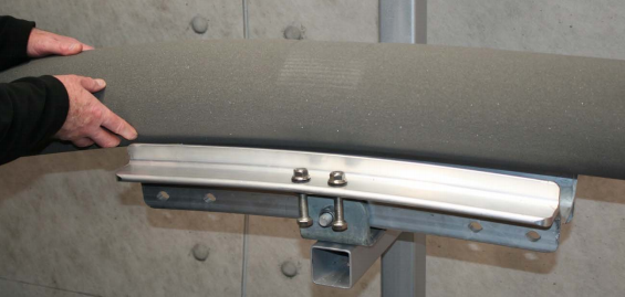
Installation instructions for single way or trefoil cables using Centaur saddles manufactured by Ellis Patents:
 |
 |
 |
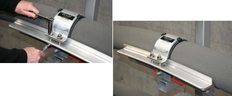 |
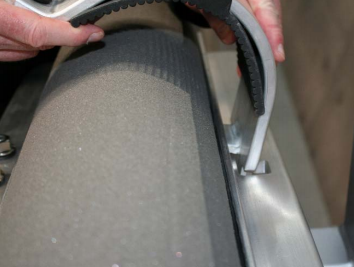
| 1. Position the Centaur onto the mounting structure.Tighten the central M16 bolt to the structure using a 24mm socket or spanner set | 2. With care install the cable into the saddle | 3. Attach the strap to the saddle, ensuring that the liner is in place. |
4. Close the strap onto the M12 fixings. Using a 19mm socket or spanner for the head of the set screws and an 18mm socket or spanner for the flange nuts, tighten the strap to an appropriate torque for the cable |
LV, MV & HV Jointing, Earthing, Substation & Electrical Eqpt
Thorne & Derrick International are specialist distributors of LV, MV & HV Cable Installation, Jointing, Duct Sealing, Substation & Electrical Equipment – servicing UK and global businesses involved in cable installations, cable jointing, substation, overhead line and electrical construction at LV, 11kV, 33kV and EHV.
THORNE & DERRICK Product Categories: Duct Seals | Cable Cleats | Cable Glands | Electrical Safety | Arc Flash Protection | Cable Jointing Tools | Cable Pulling | Earthing | Feeder Pillars | Cable Joints LV | Joints & Terminations MV HV


