

Blog
How To Apply 3M Cold Shrink Cable End Caps
June 11th, 2018
A series of How-To videos for repairing, jointing and terminating cables using 3M Cold Shrink & Scotchcast products.
Cold Shrink Cable End Caps
This video by 3M Electrical shows how to apply 3M Cold Shrink end caps safely.
3M Cold Shrink cable caps environmentally seal and mechanically protect exposed low, medium and high voltage cable ends using no tools, mastics or tapes.
The 3M video shows how cables ends can be quickly and simply sealed – simply position the end cap over the cable end and unwind the core to install the Cold Shrink cap onto the exposed cables.

Cold Shrink – invented by 3M over 40 years ago and now the preferred technology for heat-free jointing, terminating, sealing and abandonment of LV HV cables
We hope you find this video informative and educational, contact T&D for technical support, quotations and stock availability for 3M Cold Shrink Cable End Caps.
3M Cold Shrink Cable Caps Selection Chart
| 3M Cold Shrink Cable Caps Part Number | Cable Diameter Use Range (mm) |
| EC1 | 11.6 – 20.9 |
| EC2 | 15.9 – 30.1 |
| EC3 | 26.0 – 49.2 |
| EC4 | 45.5 – 84.3 |
| Test Methods | Typical Value |
| Colour | Black |
| 300% Modulus (ASTM D-412-75) | 480 psi |
| Ultimate Tensile (ASTM D-412-75) Original | 1400 psi |
| Ultimate Elongation (ASTM D-412-75) Original | 750% |
| Die C Tear (ASTM D-624C-73) Original | 150 pli |
| Fungus Resistance (ASTM G-21) 28 Days Exposure | No Growth |
| Moisture Absorption 7 Days at 90ºC in H2O | 1.8% Weight Gain |
➡ Visit 3M Electrical for further information about joints, terminations, tapes and insulation to seal, repair, splice and connect LV MV HV cables.
♦ Did you know? Cables can be insulated, protected and repaired using cold shrink tubing available in both EPDM rubber or fire resistant silicone.

Cold Shrink | Joint | Terminate | Seal | Repair | Splice | LV MV HV Cables | 3M
- 3M Electrical Products Stocked By Thorne & Derrick International
BS EN 62305 – Protection Against Lightning Strikes & Risk Management Notes
June 11th, 2018
BS EN 62305

AN Wallis manufacture earth tapes from high conductivity copper to ensure LPS designs and installations conform to latest Britsh and International standards
-
Uploaded by Chris Dodds - Thorne & Derrick Sales & Marketing Manager
BS EN 62305
The Part 2 of BS EN 62305 provides a comprehensive mathematical model to evaluate and manage the risk posed by lightning strikes and measures to alleviate the risk associated with earthing system designs.
The risk assessment is extremely time consuming to calculate by hand so Wallis, working in conjunction with their distributor Thorne & Derrick International, can offer to do the assessment using bespoke computer software.
The basics of the calculation can be briefly explained as follows taking into account:
The Sources of Lightning
- S1: flashes to a structure
- S2: flashes near a structure
- S3: flashes to a line
- S4 flashes near a line
The Likely Damage
- D1: injury to living beings by electric shock
- D2: physical damage
- D3: failure of electrical and electronic systems
The Likely Losses
- L1: loss of human life (including permanent injury)
- L2: loss of service to the public
- L3: loss of cultural heritage
- L4: loss of economic value (structure, content, and loss of activity).
The following Table 2 from BS EN 62305 explains the link between Sources, Damages & Losses.
Table 2 – BS EN 62305
Sources of damage, types of damage and types of loss according to the point of strike:
| Lightning Flash | Structure | |
| Source of Damage | Type of Damage | 1 Type of Loss |
| S1 | D1D2D3 | L1, L4aL1, L2, L3, L4 L1b, L2, L4 |
| S2 | D3 | L1b, L2, L4 |
| S3 | D1D2D3 | L1, L4a,L1, L2, L3,L4 Lib, L2, L4 |
| S4 | D3 | L1b, L2, L4 |
Note:
a) Only for properties where animals may be lost.
b) Only for structures with risk of explosion and for hospitals or other structures where failures of internal systems immediately endangers human
Risk: The risks to be evaluated in a structure may be as follows
- R1: risk of loss of a human life (including permanent injury)
- R2: risk of loss of service to the public
- R3: risk of loss of cultural heritage
- R4: risk of loss of economic value.
Risk Management
- Basic Procedure
The following procedure shall be applied:
- Identification of the structure to be protected and its characteristics
- Identification of all the types of loss in the structure and the relevant corresponding risk R (R1 to R4); evaluation of risk R for each type of loss R1 to R4
- Evaluation of need of protection, by comparison of risk R1, R2 and R3 with the tolerable risk RT
- Evaluation of cost effectiveness of protection by comparison of the costs of total loss with and without protection measures. In this case, the assessment of components of risk R4 shall be performed in order to evaluate such costs.
- Structure to be considered for risk assessment includes
- The structure itself
- Installations in the structure
- Contents of the structure
- Persons in the structure or in the zones up to 3 m from the outside of the structure
- Environment affected by damage to the structure.
Protection does not include connected lines outside of the structure.
- Tolerable Risk RT
The calculated risks R1, R2 & R3 shall be compared with tolerable risk. The permissible values for the tolerable risk are mentioned in the Table 4 BS EN 62305.
Table 4 – Typical values of tolerable risk RT
| Types of Loss | RT (y-1) | |
| L1 | Loss of human life or permanent injuries | 10-5 |
| L2 | Loss of service to the public | 10-4 |
| L3 | Loss of cultural heritage | 10-4 |
If R < RT, lightning protection is not necessary. If R > RT, protection measures shall be adopted in order to reduce R RT for all risks to which the structure is subjected.
The manual calculations are time consuming. It is recommended to use available Lightning Protection Risk Management Software to perform these calculations – contact T&D.

Thorne & Derrick International
Contact us to discuss all your Substation Earthing, Cable Jointing & Terminating requirements for the installation of LV MV HV cables, copper earthing tapes and infrastructure including switchgear, transformers and electrical equipment up to 33kV.
Product Categories: Duct Seals | Cable Cleats | Cable Glands | Electrical Safety | Arc Flash Protection | Cable Jointing Tools | Cable Pulling | Earthing | Feeder Pillars | Cable Joints LV | Joints & Terminations MV HV

Largest UK Stocks Of Copper Earthing Tapes

Earth Rods | Earth Bars | Earth Mats | Earth Clamps – manufactured from high conductivity copper by AN Wallis and supplied by Thorne & Derrick
Earthing Systems Using Air Rods & Copper Tape Conductors For Roof Termination Network (BS EN 62305)
June 11th, 2018

Earth Tapes – Bare & Covered Copper Tapes
-
Uploaded by Chris Dodds - Thorne & Derrick Sales & Marketing Manager
Copper Earthing Tapes
Thorne & Derrick International, a leading stockist and distributor of copper earthing tapes manufactured by AN Wallis and ABB Furse provide an overview of the role and relationship of earth tapes and air rods with respect to the design of Lightning Protection Systems for Roof Termination Networks in accordance with British Standard BS EN 62305.
Roof Termination Network
The roof termination network can be concealed below the tiles or cladding provided the air rods/strike pads protrude above the tiles or cladding (see below Figure 15).
Air rods to be selected based on the protection angle method. Strike pads should be provided in accordance with mesh spacing.
The air termination system will usually consist of air rods, flat tape conductors such as copper earthing tapes in a mesh or in some designs a catenary wire (in case of isolated LPS), there are three methods for the earthing system designer to determine the air termination system in the LPS, each is acceptable to BS EN 62305.
The earthing design comes from one of three options already detailed: the rolling sphere, protective angle or mesh alternatives, each method has different criteria for the roof network.
Wherever possible the air termination network should be located:
- At the corners of the building
- At the most exposed points of the building
- As close to the edge of the building as possible (on the parapet wall is usually as close as you can get)

The roof network should follow the most direct route with minimal bends. Where roof tiles are non-conducting the air-termination conductor may be placed either under, or over the roof tiles (over is always preferable), Where the conductor is sited below the tiles vertical finials or flat strike plates should be used These should be spaced at not more than 10 metres for air rods and 5 metres for strike plates (corresponding to class of LPS).

Roof Termination Network concealed below the tiles or cladding provided the air rods or strikes pads protrude above the tiles or cladding
In circumstances where two horizontal LPS air-termination conductors are placed parallel above the horizontal reference plane, the distance that the rolling sphere penetrates below the level of the conductors within the space between the horizontal conductors is:
Where
p = penetration distance r = rolling sphere radius
d = distance between the two parallel air terminal
rods or conductors
The penetration distance (p) should be less than the height of the air terminal/conductor above the roof surface/ reference plane, (ht), minus the height of objects to be protected.
[BS EN 62305-3, E4] p = r — (gr2 – (d/2)2

Protection For Open Roof Car Parks

Open Roof Car Park Protection
For car park structures where the roof is an open parking area (as shown in Figure 17) for cars, normally surrounded by a parapet wall, it is not advisable to have any kind of roof conductors as they are constantly being driven over and walked upon.
In these circumstances the standard allows the use of air rods on the parapet wall with a mesh on the roof hidden between the edges of adjoining slabs or bedded in the concrete with strike pads installed visible above the tarmac or concrete.
Persons and vehicles on this parking area are above the Lightning protection system and not protected from lightning.
If the top level of the car park has to be protected then air rods, catenary wire and natural masts such as lamp posts can be designed in to provide an enhanced protected area.
The step and touch potential risk on the top level of the car park can be overcome provided the roof is constructed of reinforced concrete with interconnected reinforcement steel with continuity provided by welding or clamping.
Conductive fixtures on the roof
Conductive roof fixtures such as AC units outside the zone of protection can be ignored if their height is under 300mm or if it’s under 1 mtr/2 or it’s less than 2mtr long.
Non conductive roof fixtures outside the zone can be ignored if less than 500mm in height.
A conducting fixture such as pipes or an air conditioning unit needing protection should be protected by an air termination system Figure 18. If this is not possible insulated parts, with lengths corresponding to at least twice the specified separation distance, can be installed on the conductive installations. [BS EN 62305-3, E5.2.4.2.4]

Conducting fixtures such as pipes or air conditioning units should be protected by an air termination system
When a non-conductive chimney falls outside the protective zone of the air-termination system, it should be protected by means of air-termination rods or air-termination conductors. The air termination rod on a chimney should be of such height that the complete chimney lies within the protective space of the rod.
[BS EN 62305-3, E 5.2.4.2.4]
Metal roof fixtures should be bonded to the air termination system when the necessary clearance for conformity to the separation distance cannot be maintained.
[BS EN 62305,3, E5.2.4.2.4]
Conductive electrical appliances and fittings on the roof are some of the most difficult problems facing the designer of the LPS if the requirements of BS EN 62305-3 are to fully met and the system be fully compliant. See Figure 19.
To fully comply with BS EN 62305
- Metallic roof fixtures such as air conditioning units must fall within a zone of protection offered in accordance with the angle of protection (or with the rolling sphere method)
- The units must also maintain a separation distance between the fixture and the protective air-termination equipment to prevent dangerous sparking (not required if. metallic fixtures are mechanically and electrically continuous with the structure)
In practice this is very difficult to achieve with the sometimes crowded nature of the average apartment block.
Protecting Fixtures Which Cannot Withstand Direct Strike To Its Casing
This is where the casing is not of sufficient cross-section area to comply with the thickness requirements of the standard, in these cases an air termination system should be installed to cover these units.
A separation distance should be maintained between the fixture and the air-termination to prevent sparking between the air-termination and fixture in the event of a lightning strike.
If it’s not possible to meet the requirements of BS EN 62305 the air-terminal should still be fitted and the fixture should be bonded to the conductor connecting to the air-termination.
Services from the fixture going into the building should be bonded to an equipotential bar and protected by installing a Type 1 Surge Protection Device.
Protecting Fixtures Which Can Withstand A Direct Strike To Its Casing
There is an option here to consider using the casing of the fixture itself as part of the air-termination network, the argument against is that electromagnetic effects of a direct lightning strike are likely to be greater than if the fixture was protected within the air termination network.
If the casing is used as part of the air termination network:
- Fixture should be bonded to the air-termination network when entering the building and connected to a equipotential bonding bar
- Any armouring or screening should be connected to a equipotential bonding bar and their live cores connected to the same bar using SPDs
It could be argued this is introducing the lightning strike into the building but the alternative to this approach would be to ensure that all mechanical services are insulated where they enter the building and split cables fitted with SPD’s which in the majority of cases is not practical.
Electrical Installation outside the zone of protection
If it’s just not possible to have antenna masts, satellite dishes and other electrical equipment within the zone of protection they should as a minimum be bonded into the LPS in at least two positions.
It’s unlikely all cables and other provisions will enter the building in the same place so as a all conductive sheaths and conductive mechanical protection should be bonded to the lightning protection air-termination by means of a common earth bar.
Lightning Protection for Structures Covered by Soil
Structures with a layer of soil on the roof where people are not regularly present should be fitted with a meshed air-termination system sited on top of the soil. Practically, a permanent fixed mesh could be installed. Alternatively, air termination rods sited in accordance with the rolling sphere or protective angle method and connected by a buried mesh may be used see BS EN 62305-3, E.5.2.4.2.8.
If people are likely to be present a mesh 5mtr x 5mtr should be installed beneath the soil to protect against step potentials but practically there would need to be visual warnings to the public advising against being in the area in the event of a lightning storm.
In the case of underground bunkers containing explosives an interconnected isolated LPS should be fitted as well as the mesh.
Natural Components As Part Of The Air Termination Network
Below are all permissible as part of the air termination network in the LPS according to BS EN 62305.
Metal Sheets
- Provided there is reliable and durable electrical continuity between the various parts and it’s not clad with insulation
- The thickness of the metal sheet meets the minimum dimensions shown in Table 1
- R’s permissible to use this metalwork but unlikely any designer would accept puncturing of the membrane in the event of a direct strike so as a minimum air rods should be fitted to the perimeter
- Metalwork on the roof, railings, lights, water tanks, coverings provided the metalwork meets the minimum dimensions shown in Table 1
- Even pipes and tanks carrying combustible materials can be considered provided the provided they are constructed of material with thickness not less than the standard allows (for detailed information [BS EN 623053, Annex E]
If the metallic parapet is to be used as part of the air-termination network it has to be both electrically and mechanically continuous, the minimum thickness should comply with the dimensions in Table 1 and Figure 23.
Table 1
| Material for LPS Level I To IV | Prevents puncture, hot spots or ignition (minimum thickness mm (ta) requirement | Only for metal sheets where preventing puncture, hot spots or ignition is not important. Minimum thickness mm (ta) requirement |
| Lead | – | 2.00 |
| Stainless Steel | 4 | 0.50 |
| Titanium | 4 | 0.50 |
| Copper | 5 | 0.50 |
| Aluminium | 7 | 0.65 |
| Zinc | – | 0.70 |
If a metallic roof parapet is not being used in the air-termination network then it should be bonded every 20 metres along the complete length and to each down-conductor (or at down conductor spacing).
Conductive metal objects above the roof surface and passing through the roof structure should be bonded onto the air termination network., examples of this could be a water tank with pipe work passing through the roof into the structure.

Example of Wallis Earth Bonds
Thorne & Derrick International
Contact us to discuss all your Substation Earthing, Cable Jointing & Terminating requirements for the installation of LV MV HV cables, copper earthing tapes and infrastructure including switchgear, transformers and electrical equipment up to 33kV.
Product Categories: Duct Seals | Cable Cleats | Cable Glands | Electrical Safety | Arc Flash Protection | Cable Jointing Tools | Cable Pulling | Earthing | Feeder Pillars | Cable Joints LV | Joints & Terminations MV HV
Largest UK Stocks Of Copper Earthing Tapes
Earth Rods | Earth Bars | Earth Mats | Earth Clamps – manufactured from high conductivity copper by AN Wallis and supplied by Thorne & Derrick
Copper Earthing Tapes For Down Conductors – Some General Considerations
June 10th, 2018
Copper Earthing Tapes – Bare & Covered Copper Tapes
-
Uploaded by Chris Dodds - Thorne & Derrick Sales & Marketing Manager
Copper Earthing Tapes
Thorne & Derrick International, a leading stockist and distributor of copper earthing tapes manufactured by AN Wallis and ABB Furse provide an overview of the role and relationship of earth tapes with respect to the design of Lightning Protection Systems in accordance with British Standard BS EN 62305.
Down conductors
Some general considerations for the use of copper earthing tapes as down conductors are as follows unless the Earthing & Lightning Protection System (LPS) is isolated:
- There should be at least two down conductors around the building
- The down conductors should be as equally spaced as possible
- Copper earth tape as down conductors should be installed at exposed corners of building
- Down conductors can be fixed to any wall or surface which is non-combustible, if the surface is combustible refer to BS EN 62305 for guidance
- Down conductors must not be sited in gutters or down pipes
- The down conductor ideally will follow the shortest and most direct path to earth
- The down conductor should as far as possible be straight and vertical
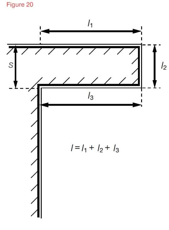
- Wherever possible avoid any re-entrant loops where this is not possible the separation distance shown in Figure 22 Is required as a minimum, if this cannot be achieved another design for the down conductor system should be considered
- A test joint should be fitted on each down conductor to enable disconnection from the earth network and provide access for earth resistance measurement and maintenance
The bottom 3 metres of the down conductor should be protected within a metal guard or PVC covering at least 3mm thick to deter vandalism and copper earthing tapes theft Figure 21. The test clamp should be fixed above the capping wherever possible Figure 21.
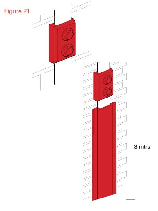
Down Conductor should be protected by metal guard of PVC covering at least 3mm thick to deter vandalism
If the air termination is a metal rod on a non conductive mast, at least one down conductor is needed for each mast.
No additional down conductors are required for masts made of metal or interconnected reinforcing steel.
If the air termination consists of one or more catenary wires at least one down conductor is needed at each supporting structure.
Positioning the down conductors
There should be multiple down conductors following the shortest possible path to earth via the conductive copper EARTH tapes.
Typical values of the distance between down conductors, subject to architectural and practical constraints are given in the table below.
Table 5.4 – Typical down conductor spacing’s and distance between ring conductors
| Class of LPS | Typical Ring Distances (M) |
| I | 10 |
| II | 10 |
| III | 15 |
| IV | 20 |
It may not be practically possible to space the down conductors exactly as required, so the spacing’s can be adjusted by ±20% but the average spacing of all down conductors must conform to the typical distances for the class of LPS.
If it is not possible to place down conductors at a side or part side of the building the down conductors that should be on that side should be placed as additional down conductors compensating for the other sides. The distance between the installed down conductors should not be less than one-third of the required down-conductor distances dependent upon the class of LPS.
Equipotential bonding to conducting parts of the structure should be performed according to BS EN 62305-3, 6.2.
The distance between the down-conductor and the internal services must satisfy the distance requirements covered in the table above.
If the separation distance required to avoid dangerous sparking between the down conductor and the internal services cannot be satisfied, the number of down conductors should be increased until the required separation distance is met.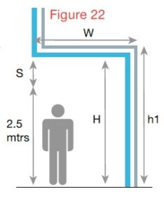
Protection on a Cantilevered Structure
There is a risk when the down conductor goes into a cantilever that a strike could flash over to this risk the separation distance, h in metres, should satisfy the the person standing underneath 2.5 as shown in figure 22. To reduce mtrs following conditions.
H > 2.5 + S
S – Is the separation distance in metres calculated.
2.5 – represents the height of a typical person with their hand in the air.
Using natural components as down conductors
The natural components can be used as down conductors provided the components comply with the requirements of BS EN 62305.
The natural components can be used provided there is electrical continuity, where the joints are tightly bolted they can be considered as electrically continuous Figure 23.
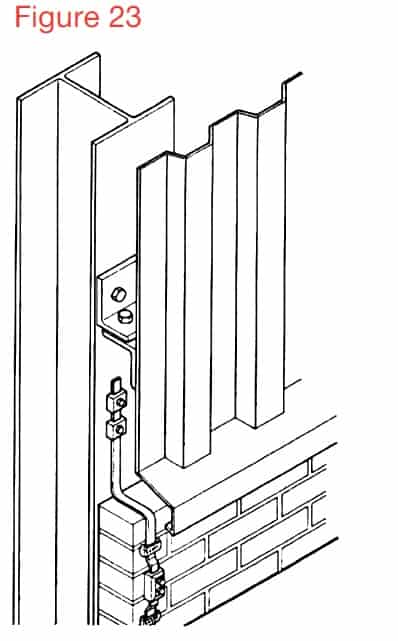
Natural components as down conductors
The facade elements, profile rails and metallic sub-constructions of facades can be used provided their dimensions conform to the requirements for down conductors and metal sheets or metal pipes, not less than 0.5mm thick.
If the metal façade of the building is to be used as the down conductor then BS 62305 offers specific guidance.
Each overlapping vertical joint at each down-conductor position should be bridged by flexible metal strapping. See Figure 24.
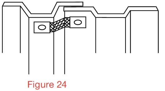
Overlapping vertical joint bridged by flexible metal strapping
Connections between the sheet metal panels should have a minimum contact surface area of 50 sqmm and be capable of be capable of withstanding the mechanical forces of a lightning discharge.
If access to the rear of the façade is not possible and the only type of fixing available for connections between facade sheets and the air termination or down-conductor tapes is pop rivets then these should be at least four 5mm diameter rivets and used on a length of conductor, such as copper earth tape, a minimum of 20mm long. (C.S.A or conductor (connection component) min 50 sqmm).
Down conductors not using the
natural components of the building
Where down conductors are installed on the building not using the natural components then consideration needs to be given to the separation distance between the internal columns and internal partition walls with conductive parts.
If these conductive columns and partitions do not satisfy the separation distance conditions they must be connected to the air termination system at roof level and to the earthing network at ground level.
What Is BS EN 62305-3:2011?
Part 3 of EN 62305 sets out all the requirements needed to protect buildings and structures against physical damage by implementing a lighting protection system (LPS). It also looks at how to protect humans and animals (living beings) against injury if they are close to an LPS. By defining these safety measures, this standard helps you to minimise damage, invest in the right electrical protection equipment and maximise hazard prevention in buildings.

Thorne & Derrick International
Contact us to discuss all your Substation Earthing, Cable Jointing & Terminating requirements for the installation of LV MV HV cables, copper earthing tapes and infrastructure including switchgear, transformers and electrical equipment up to 33kV.
Product Categories: Duct Seals | Cable Cleats | Cable Glands | Electrical Safety | Arc Flash Protection | Cable Jointing Tools | Cable Pulling | Earthing | Feeder Pillars | Cable Joints LV | Joints & Terminations MV HV
Largest UK Stocks Of Copper Earthing Tapes
Earth Rods | Earth Bars | Earth Mats | Earth Clamps – manufactured from high conductivity copper by AN Wallis and supplied by Thorne & Derrick
Cembre B1350-CE v. B135-C Crimping Tools Performance Comparison
June 10th, 2018
-
Uploaded by Chris Dodds - Thorne & Derrick Sales & Marketing Manager
Cembre B1350-CE v. B135-C
Since 1985, Thorne & Derrick International have been Main UK Stockists and Suppliers of the range of Cembre tools manufactured to crimp and cut all types of cables.
The following information table presents a comparison of performance between the now obsolete Cembre B135-C and its technologically advanced replacement model the Cembre B1350-CE battery crimping tool.
Cembre B1350-CE crimping tool delivers a 132kN compression force and accepts semi-circular slotted crimp die sets for installing LV MV HV lugs and connectors up to 400sqmm, including 11kV and 33kV cable lugs.
Full supporting range of die sets manufactured by Cembre are available for use with both hydraulic and battery type operated crimping tools up to 400sqmm.
The Cembre B1350-CE tool features a new generation Li-Oin 18V 4Ah battery providing higher capacity, faster charging time and improved energy efficiency of the overall crimping process – should you require any further information please do not hesitate to contact us.
For competitive prices, stock availability and technical advice about the Cembre B1350-CE tool please do not hesitate to contact us.
| Crimping Tool Test Criteria | B1350-CE Crimp Tool Cycle Time | B135-C Crimp Tool Cycle Time | B1350-CE Crimps Per Battery Charge | B135-C Crimps Per Battery Charge |
| Cable Lug A2-M
Die Sets ME2-C Cable Flexible Copper 10sqmm |
4.49
31% faster than B135-C |
6.47 | 237
74% more than B135-C |
136 |
| Cable Lug A5-M
Die Sets ME5-C Cable Flexible Copper 25sqmm |
4.68
34% faster than B135-C |
7.07 | 228
89% more than B135-C |
121 |
| Cable Lug A24-M
Die Sets ME24-C Cable Flexible Copper 120sqmm |
7.12
24% faster than B135-C |
9.37 | 141
61% more than B135-C |
87 |
| Cable Lug A48-M
Die Sets ME48-C Cable Flexible Copper 240sqmm |
8.23
26% faster than B135-C |
11.19 | 116
81% more than B135-C |
64 |
| Cable Lug C70-C70
Die Sets MC70-50 Cable Flexible Copper 70sqmm |
7.88
27% faster than B135-C |
10.79 | 128
68% more than B135-C |
76 |
| Cable Lug C120-C120
Die Sets MC185-C Cable Copper 120sqmm |
10.61
23% faster than B135-C |
13.77 | 88
70% more than B135-C |
52 |

LV Lugs & Connectors – complete range of copper crimp connectors suitable for use with joints and terminations for low voltage cables | Cable Lugs | Cable Splice Connectors | Aluminium Lugs | Aluminium Splices | Bi-Metallic Cable Lugs

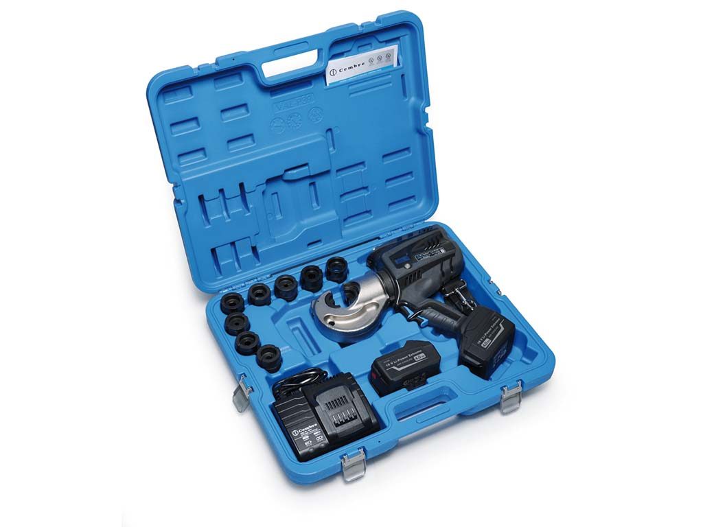
Cembre B1350-CE is supplied with a robust protective plastic carry case suitable for storing the crimping tool and 7 die sets.

HV Lugs & Connectors – complete range of copper crimp connectors suitable for use with joints and terminations for medium/high voltage cables | Cable Lugs | Transformer Lugs | 2 Hole Lugs | Pin Stalk Connectors | Through Connectors | 11kV 33kV
THORNE & DERRICK
Key Product Categories: Duct Seals | Cable Cleats | Cable Glands | Electrical Safety | Arc Flash Protection | Cable Jointing Tools | Cable Pulling | Earthing | Feeder Pillars | Cable Joints LV | Joints & Terminations MV HV
