

Medium Voltage Cable Accessories – Best Practice Guide
Earth Bonding | Joints & Terminations & Overheating Prevention
January 10th, 2020
Earth Bonding
Earth bonding across joints and at terminations does not always receive the level of care and attention that it requires. An ineffective earth bond can be just as damaging to MV cable accessory performance as inadequate phase conductor connections. It is also possible that medium voltage electrical power network safety may be compromised if an earth connection is lost or has high resistance.
A failure mechanism frequently seen in joints and terminations is overheating at positions where the cable metallic screen and/or armour is connected across a joint or to an earth connection at a cable termination. Overheating results when a high resistance earth bond carries fault current or induced ‘circulating current’. The overheating can damage underlying cable insulation and cause insulation failure of the MV power cables.
The most frequent cause of earth bond problems is the presence of continuous induced earth circulating currents in single-core circuits. These circulating currents are induced in the metallic earth components of the cable if there is a connection to earth at each end of the cable (referred to as ‘solid bonding’).
The problem is likely to be worse in circuits with large conductor cables with aluminium wire armour (AWA). Because of the high conductivity of AWA, the circulating current can be many hundreds of Amps when the cable conductor is heavily loaded.
Unfortunately, MV cable accessory suppliers are not always made aware of the possibility of circulating currents when asked to specify products such as MV joints, terminations or connectors. The installer should be in a good position to know the system earthing arrangements and to check before installation whether the earth bonds provided with the accessory are adequate. If there is doubt, installation should not proceed.
Further Reading
- Cables | MV Paper Insulated v MV Polymeric Insulated Cables
- The Installation Site | MV Cable Joints & Cable Terminations
- First Steps | MV Joints, Jointers & Initial Considerations
- Cable Preparation | Jointing & Terminating Aspects of MV Cable Preparation
- Conductor Connectors | Crimp v Mechanical Connectors with Joints & Terminations
- MV Cable Accessory Technologies | Heat Shrink, Cold Shrink & Push-on
- MV Cables & Causes of MV Cable Failures
- MV Cables | Electric Field & Stress Control

LV, MV & HV Jointing, Earthing, Substation & Electrical Eqpt
Thorne & Derrick International are specialist distributors of LV, MV & HV Cable Installation, Jointing, Duct Sealing, Substation & Electrical Equipment – servicing UK and global businesses involved in cable installations, cable jointing, substation, overhead line and electrical construction at LV, 11kV, 33kV and EHV.
THORNE & DERRICK Product Categories: Duct Seals | Cable Cleats | Cable Glands | Electrical Safety | Arc Flash Protection | Cable Jointing Tools | Cable Pulling | Earthing | Feeder Pillars | Cable Joints LV | Joints & Terminations MV HV
Conductor Connectors | Crimp v Mechanical Connectors with Joints & Terminations
January 10th, 2020Crimp v Mechanical Connectors with Joints & Terminations
Within joints and terminations, conductor connectors are responsible for carrying the electric current between cables or between cable and other electrical equipment such as switchgear, transformers and overhead lines. They are therefore fundamentally important components of electrical networks.
Connectors that are not the right size or type, or not correctly installed, can cause failure of the MV cable accessory. Two common types of failure are:
- Overheating or ‘burn-out’ of the connector and accessory due to high electrical resistance
- Electrical breakdown of a joint if the connector is the wrong shape (causing raised electrical stress)
- See BS7609 | Crimping Cables With Cembre Cable Lugs & Tools
The original method of making connections to cable conductors was by soldering or brazing.
This has now been replaced by two technologies, both of which have proved highly reliable if components are correctly selected and correctly installed. These connector categories are:

BS7609 Crimping Cables With Cembre Cable Lugs & Tools
Whatever the connector type, it is essential to check that the connector is compatible with the accessory to be installed. This is vital for all styles of cable joint and may be similarly important for cable terminations. It is preferred that connectors are included in the accessory kit because selection of the right connectors has already been done by the accessory manufacturer or supplier. If connectors are not included, the supplier must provide guidance (in the installation instruction or other documentation) as to the types and sizes of connector that are suitable. Before starting work, the installer should make every effort to check that the connectors have been correctly selected.
For all connector types, the correct length of insulation must be removed from the conductor to allow full insertion into the connector body. Installation instructions will specify any gap, or none, between connector body and insulation cut edge.
Before installing any connector, the exposed cable conductor must be clean and free from any contamination. The connector installation instruction may require that the conductor surface is abraded with a wire brush or abrasive cloth. The internal surface of the connector may have a coating of grease or other interface compound, in which case it should not be removed and must be protected from contamination. A connector with a grease coating will normally be supplied in protective packaging and it is good practice to remove the packaging only immediately before installation.
Installers should check some general requirements for compression and mechanical connectors used for main conductor connections:
- Connectors for transition joints should be ‘blocked’ to prevent impregnating compound from the paper cable finding its way across the joint into the polymeric cable, or water in the polymeric cable entering the paper cable.
- Connectors for terminations (‘cable lugs’) should not have a ‘sight hole’ into the connector barrel, which could allow entry of moisture.
Compression (‘crimp’) connectors are installed using special equipment comprising a powered hydraulic or hand-operated press tool together with a die set.
There are two main connector types in common use:
- Hexagonal or circumferential compression
- Deep indent compression
Compression Connectors

Die Sets: Hexagonal types. Manufactured by Cembre.
For both techniques it is essential that:
- The connector is the right size and type for the conductor
- The die set is correct for the type and brand of connector
- The die set is correct for the conductor cross-section (mm²) or diameter
- The press tool and the die set are compatible
- The press tool and die set are maintained in good condition
Compression connectors for MV applications are not normally range-taking and are each intended for a specific conductor size.
A connector is also likely to be specific to the material and construction of the cable conductor (metal type, stranded or solid, round or shaped).
Application details must be thoroughly checked to ensure that the connector and conductor are compatible.
Installers should be aware that the diameters of modern cable conductors may be smaller than was envisaged when the compression connector was designed. This may result in a connector being a ‘loose’ fit on the conductor even though it is the correct size for the conductor cross section. The installer must not be tempted to select a connector for a smaller conductor cross-section even if it will fit on the conductor. This is because the smaller connector may not have adequate metal cross-section to suit the conductor size.
Hexagonal compression takes its name from the shape of the die used to compress the connector body on to the conductor (see Figure 34). Connectors have a cylindrical shape and usually have guide marks to show the correct positions of the die for installation. There may be more than one compression position on each side of the connector. With hexagonal compression connectors, the first compression must be the one nearest to the centre of the connector body. Subsequent compressions are next to the previous one, moving towards the end of the connector.
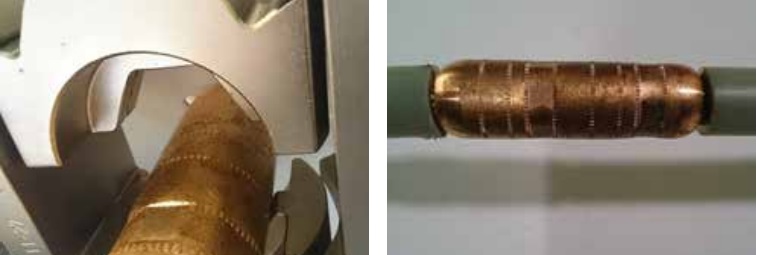
Figure 34 – Hexagonal compression die and copper connector (for stranded copper conductor) showing first compression position
Figure 35 shows a hexagonal compression lug with tool guide marks on the barrel.
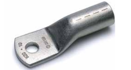
Figure 35 – Compression lug showing guide marks for hexagonal compression tool positions
For deep indent compression, as the name implies, an indenting tool is pressed deep into the connector body. Because of the amount of disruption caused by the crimping tool, the connector body must be fully supported in a cage which forms part of the tooling equipment (see Figures 36 and 37).
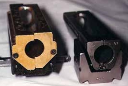
Figure 36 – Die cage for deep indent tool
A very important difference between these two compression technologies is the sequence of compressions. With hexagonal compression the first tool position is nearest to the connector centre, but with deep indent compression the first tool position is at the end of the connector, working towards the centre.
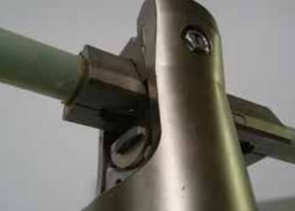
Figure 37 – Second deep indent position
After installation, compression connectors should be carefully checked for any sharp edges or points. It is essential that any sharp edges or points are removed using a file or abrasive cloth. The installation instruction may include this step. The connector body and nearby surfaces must then be thoroughly cleaned to remove any metal particles or other contaminants. Installation instructions may also require the depressions in the body of deep indent connectors to be filled with a mastic or putty (usually supplied in the kit).
Bolted connectors
Bolted (or ‘mechanical’) connectors have screws which are tightened to contact the conductor within the bore of the connector. These connectors are steadily gaining in popularity because they are size range-taking (which is convenient for inclusion in accessory kits) and usually require no special installation tooling. In addition, most of those for MV applications have shear-head screws where the screw head or part of the screw shank breaks away when the correct tightening torque is reached. This takes away requirement on the installer to apply a controlled torque. Sheared screws generally leave a relatively smooth profile over the cylindrical body of the connector. Any projecting points or edges must be removed using a file or abrasive cloth.
Bolted connectors may be installed using standard hand wrenches if the screws have hexagonal heads (see Figure 38) or hexagonal sockets (see Figure 39). The sequence of screw shearing is from the screw nearest the connector end, working towards the centre. It is good practice to tighten screws progressively from one to another until all are tight but not sheared. The first screw should then be further tightened until it shears.
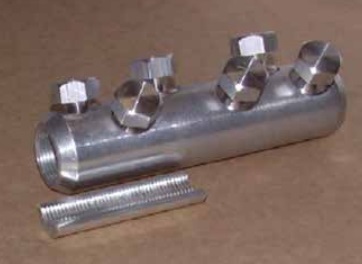
Figure 38 – Bolted connector with hexagonal head
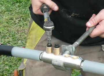
Figure 39 – Bolted connector with hexagonal socket
The use of a hand-operated wrench gives maximum control over the tightening and shearing procedure but some connector manufacturers allow the use of power impact wrenches to tighten and shear the screws. It is essential that the installation method is in accordance with the connector installation instruction or the manufacturer’s recommendation.
Range-taking of bolted connectors may extend to three or more standard conductor sizes. These connectors will probably be fitted with screws having several shear positions (Figure 40 left) or a ‘step-less’ shear feature making the screw shear flush with the connector surface (Figure 40 right). With most joints and terminations it is important that the sheared screw thread does not project above the cylindrical profile of the connector body after installation.
The installation instruction may require the use of a file or abrasive paper to remove any projections of the sheared screws. If this is the case, metallic filings or dust must be completely cleaned from the connector body and nearby surfaces.
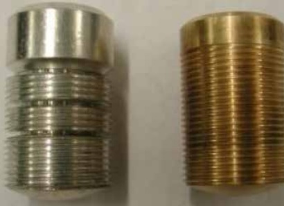
Figure 40 – Multi-shear position (left) and step-less shear (right) screws
Range-taking bolted connectors may include metal inserts (see Figure 38) or plastic centring rings (see Figure 41) intended to position smaller conductors concentric within the bore of the connector. Centralising inserts must be used (for smaller conductors) or discarded (for larger conductors) according to the installation instruction.
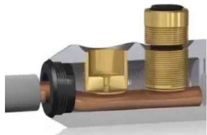
Figure 41 – Plastic insert (black) for centring a small conductor in the connector body
It is good practice to use a connector support tool to prevent twisting of the connector (see Figures 39 and 42). This is particularly necessary when working with small cable conductors to avoid bending of the conductor either side of the connector.
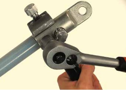
Figure 42 – Use of a support tool for installation of a shear-head mechanical lug
Further Reading
- Cables | MV Paper Insulated v MV Polymeric Insulated Cables
- The Installation Site | MV Cable Joints & Cable Terminations
- First Steps | MV Joints, Jointers & Initial Considerations
- Cable Preparation | Jointing & Terminating Aspects of MV Cable Preparation
- Earth Bonding | Joints & Terminations & Overheating Prevention
- MV Cable Accessory Technologies | Heat Shrink, Cold Shrink & Push-on
- MV Cables & Causes of MV Cable Failures
- MV Cables | Electric Field & Stress Control
LV, MV & HV Jointing, Earthing, Substation & Electrical Eqpt
Thorne & Derrick International are specialist distributors of LV, MV & HV Cable Installation, Jointing, Duct Sealing, Substation & Electrical Equipment – servicing UK and global businesses involved in cable installations, cable jointing, substation, overhead line and electrical construction at LV, 11kV, 33kV and EHV.
THORNE & DERRICK Product Categories: Duct Seals | Cable Cleats | Cable Glands | Electrical Safety | Arc Flash Protection | Cable Jointing Tools | Cable Pulling | Earthing | Feeder Pillars | Cable Joints LV | Joints & Terminations MV HV
Cable Preparation | Essential Jointing & Terminating Aspects of MV Cable Preparation
January 10th, 2020
CABLE PREPARATION
With every MV cable accessory, the cable being jointed or terminated forms a vital and integral part of the completed cable joint or cable termination.
The early stage of accessory installation is preparation of the cable ends. There is nothing more important than to do this part of the work accurately and skilfully.
Before starting work to prepare the cable ends, it is essential that an adequate length of cable outer sheath near to the working area is thoroughly cleaned and dried and kept in this state throughout the installation procedure.
For some types of MV cable accessory there is a requirement to ‘park’ components on the cable prior to installing them in their final position.
Even if the cable sheath is clean, it is good practice to cover the section of sheath where accessory components will be parked. For this purpose some manufacturers recommend using the plastic bags that components were supplied in.
Techniques involved in the preparation of cables are quite different for paper cables and polymeric cables. The following two sections highlight the most important steps for each MV cable type.
Cable Innovation Tools & Accessories for Low & High Voltage Power Systems
THORNE & DERRICK are Specialist Distributors of LV HV Cable Jointing, Earthing, Substation & Electrical Eqpt up to 66kV – this includes the most extensive range of Ex Stock Innovation Tooling to facilitate safe and reliable preparation, termination and installation of cables.

Preparation of polymeric cables
Compared with paper cables, polymeric cables appear easy to work with. They have no oily impregnating compound, are generally lighter in weight and more flexible.
The perception that the technology change from paper to polymeric cables has ‘de-skilled’ the installation process has probably contributed to a more casual approach to training of cable jointers. The result, seen by those who investigate accessory failures, is that the great majority of failures involving polymeric cables could easily be avoided by accurate and good quality cable preparation.
Many special tools are available to assist the correct preparation of polymeric cables for jointing and terminating. The use of special jointing tools will make the job easier, safer and less likely to result in serious error.
The cable outer sheath will probably have metallic components immediately under it, or may be bonded to an aluminium laminate. In each case use an appropriate sheath removal tool rather than an unguarded knife. The appropriate tool will help prevent damage to the underlying component, which may typically be copper wires, copper tape or armour wires.
In the case of cables with aluminium laminate sheaths, the special tool should include the capability for preparing the sheath for an earth bonding connection if required. Figures 15-17 show tools designed to aid the removal of plastic cable sheaths.

Figure 15 – Sheath removal tool

Figure 16 – Using a sheath removal tool

Figure 17 – Sheath removal tool for cables with aluminium laminate sheaths
Depending on the design of cable, whether single-core or 3-core, there may be other layers to remove before the black conductive screen (‘semicon’) of the phase core is exposed.
Removal of the black conductive semicon screen layer covering the insulation is a critically important stage in the preparation of polymeric cables. This screen layer is extruded together with the insulation and the inner conductor screen. Its thickness is generally between 0,3 mm and 0,6 mm and there are two types used in modern MV cables.
These are:
- ‘peelable’ (non-bonded) screens which can be peeled away from the insulation to leave a smooth clean surface, and
- ‘bonded’ screens which, as the term implies, are firmly bonded to the insulation and can only be removed using a tool which cuts off the screen layer but leaves an acceptably smooth insulation surface.
A third type of screen found in some older generation MV cables comprises a conductive paint or ‘varnish’ applied to the insulation surface and covered with an overlapped conductive fabric tape. Removal of this type of screen is mentioned on a later page.
Techniques and tools for screen removal are quite different for each type, but the important rule for both is:
- NEVER use an unguarded knife. This includes broken glass and any other object with a sharp unguarded edge.
If an unguarded knife is used, there is a very significant risk of cutting into the insulation at the screen edge. A knife cut may be invisible but will almost certainly become a future failure site, possibly immediately the cable system is energised but certainly after several months or years. The knife cut will likely be a site of partial discharge activity which would probably be detected if analytical tests were applied to the system before or during service.

Figure 18 – Knife cut into the insulation surface caused by use of an unguarded knife
For peelable screens, the technique is to make spiral or longitudinal cuts into the screen to a depth less than its thickness, allowing the layer to be removed in one or more strips to the dimension given in the installation instruction. Depth-guarded knives made for this application can be adjusted for various cutting depths. A vital step before using any guarded knife tool is to set the cutting depth appropriate to the thickness of the screen layer.
This is best done by experiment using a spare length of the same cable.
The cable cutting depth must be sufficient to allow the screen to be peeled but must not penetrate the full depth of the layer.
Some MV accessory manufacturers and users recommend removing a ring of peelable conductive screen material at the screen edge position using a round file. This is done before removing the rest of the screen layer. The file is used carefully and uniformly around the cable until the underlying insulation is just visible (see Figure 19). The claimed advantage is that no knife is involved so there is no danger of cuts in the insulation at the screen edge.
The unwanted screen length may then be peeled away after scoring the material with a guarded knife or other suitable tool (see Figures 20 and 21).

Figure 19 – Using a round file to create a screen edge

Figure 20 – Using a depth-guarded knife to score the screen

Figure 21 – Peeling strips of screen

Figure 22 – Finished screen edge and smooth
The result should be a clean screen edge and smooth insulation surface, as shown in Figure 22.
For bonded screens, many special tools are available. The most popular and successful tools all work on the same principle. After setting up the tool according to the diameter over the screen and the screen depth, the tool is moved in a spiral motion from the cable end to the screen cut position. As in the case of peelable screen tools, the tool should preferably be correctly set by experiment using a spare length of cable.
Figures 23-25 show a screen removal tool in use.
")
Figure 23 – Setting the correct cutting depth etc at the cable end (if no spare is available)

Figure 24 – The tool moves in a spiral motion along the core
In order to remove enough but not too much insulation, a practical guide is to set the removal tool so that the strip being removed shows ⅔ black screen and ⅓ insulation across its width (see Figure 25).

Figure 25 – This cutting tool creates a tapered screen edge at the selected position
Other bonded screen removal tools are shown in Figure 26.

Figure 26 – Spiral cut bonded screen removal tools
The essential result after using the tool is:
- complete removal of the screen layer without removing more than a very thin layer of insulation;
- screen edge free from projections or filaments;
- smooth insulation surface with no remaining conductive material.
Figures 27-29 show three examples of unacceptable screen edge quality resulting from incorrect use of a screen removal tool. In all cases there would be raised electric stress at the irregularities in the screen edge, probably leading to early-life failure of the accessory.

Figure 27 – Irregular conductive screen edge caused by incorrect use of the removal tool

Figure 28 – Irregular edge of peelable screen
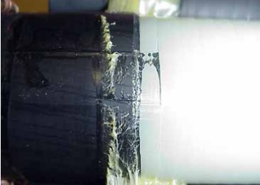
Figure 29 – Incomplete removal of conductive screen material from insulation surface
The quality of the screen edge is vital to the performance of the accessory in service. Irregularities or knife cuts into the insulation are positions of raised electric stress which will inevitably result in early-life failure. Installers must be aware of this and pay great attention to this stage of the accessory installation process.
Figure 30 shows an unacceptably rough insulation surface caused by an incorrectly set screen removal tool or gross misuse of the tool by the installer. It is good practice to smooth any minor surface roughness using abrasive cloth (preferably aluminium oxide type).
The degree of surface roughness shown in Figure 30 is, however, beyond any reparatory treatment.

Figure 30 – Extremely rough insulation surface resulting from incorrect setting and/or misuse of screen removal tool
It is good practice to make available a short length of ‘waste’ cable core to adjust and check the tool setting, and become familiar with its use.
After cutting the core (conductor and insulation) to length, removal of the insulation to fit the connector will be made easier using the appropriate special tool. If a knife is used, great care should be taken to achieve a straight cut edge and avoid scoring the surface of the conductor.
Cutting into XLPE insulation with a knife is made easier if the insulation is warmed. Figure 31 shows spiral cut insulation removal tools in use.

Figure 31 – Spiral-cut insulation removal tools in use
Some accessories, especially for higher voltage cables, may require that the edge of the insulation is chamfered (tapered). Tools such as those shown in Figure 32 are available for this purpose.

Figure 32 – Tool for chamfering the insulation edge
Before installing components of the joint or termination, the prepared cable core should be cleaned to remove any dirt or other contaminants. This should be done using clean cloths and a recommended cleaning agent. Wiping of the insulation should always be done towards the conductive screen. A cloth that has been wiped over the screen should be discarded and replaced with a clean one. Similarly, the connector should be wiped without allowing the wiping cloth to contact the insulation surface.
Some older polymeric cables do not have an extruded conductive screen. The screen in these cables will probably be a black conductive graphite-based ‘paint’ covered by a conductive fabric tape. To prepare a screen edge, the tape is unwound and fixed at an appropriate position back from the screen edge position. The exposed conductive paint is then masked with tape and the conductive paint is removed to the screen edge position using a recommended solvent.
Preparation of paper cables
Because paper cables are no longer installed as standard in European MV networks, installers will probably only have to work with them when making transition joints to newly-installed polymeric cable. Installers who are not familiar with paper cables should take special training before working with them.
The paper cable to be jointed may have been in the ground for several decades, working reliably while undisturbed. Paper is a natural material and suffers from ageing as a result of long term exposure to raised temperature during service. The most damaging result of ageing is embrittlement of the paper tapes, making them likely to crack or break when the cable core is moved. Broken insulating papers will significantly weaken the electric strength of the insulation as a whole. The following is best practice when handling paper cables.
- Handle with care when positioning the cable. Steel armour layers may have been weakened by long-term corrosion and may not offer mechanical support to the cable.
- Do not bend the cable any more than is strictly necessary. Remember that the paper insulation will be more brittle than when the cable was made. Bending the cable imposes mechanical forces on the individual paper layers. If the paper tapes crease or crack, the cable insulation will probably fail during service.
- Remove the metallic sheath only when necessary. Once the paper insulation is exposed it will absorb moisture and become electrically weaker. Beyond this point installation work should proceed without delay.
- If possible, do a moisture test on the paper insulation to prove that it has not been exposed to the environment. If the insulation proves to be ‘wet’, installation work should not proceed. If possible, avoid working with paper cables in very cold temperatures because the paper tapes will be more vulnerable to cracking.
- With 3-core cables, support the cable crutch when separating and setting the cores into position. Support the crutch with a firm hand or wrap it with strong cloth tape. A common mode of failure in 3-core transition joints is electrical breakdown in the paper cable crutch due to over-bending of the cores causing damage (cracking, splitting, creasing) to paper insulation layers.
Figure 33 shows one method for removing a lead sheath. Whatever sheath removal method is used, it is essential to avoid any damage to the underlying paper insulation. Because the paper surface is likely to be covered with sticky compound it must be thoroughly protected against contamination during the installation process.

Figure 33 – A technique for removing lead sheaths
Further Reading
- Cables | MV Paper Insulated v MV Polymeric Insulated Cables
- The Installation Site | MV Cable Joints & Cable Terminations
- First Steps | MV Joints, Jointers & Initial Considerations
- Conductor Connectors | Crimp v Mechanical Connectors with Joints & Terminations
- Earth Bonding | Joints & Terminations & Overheating Prevention
- MV Cable Accessory Technologies | Heat Shrink, Cold Shrink & Push-on
- MV Cables & Causes of MV Cable Failures
- MV Cables | Electric Field & Stress Control
LV, MV & HV Jointing, Earthing, Substation & Electrical Eqpt
Thorne & Derrick International are specialist distributors of LV, MV & HV Cable Installation, Jointing, Duct Sealing, Substation & Electrical Equipment – servicing UK and global businesses involved in cable installations, cable jointing, substation, overhead line and electrical construction at LV, 11kV, 33kV and EHV.
THORNE & DERRICK Product Categories: Duct Seals | Cable Cleats | Cable Glands | Electrical Safety | Arc Flash Protection | Cable Jointing Tools | Cable Pulling | Earthing | Feeder Pillars | Cable Joints LV | Joints & Terminations MV HV
First Steps | MV Joints, Jointers & Initial Considerations
January 9th, 2020MV Joints, Jointers & Initial Considerations
Before agreeing to do the requested work, the installer should ask himself if he has received adequate and relevant training, including jointer training, appropriate to:
- the system voltage;
- the cable(s) involved;
- the cable accessory type and technology.
If the honest answer is ‘no’, the installer should not continue with the work.
The cable accessory kit will normally include, in addition to the components to be installed:
- a parts list and
- an installation instruction
No work on MV cable preparation should begin until the installer is confident that all parts and materials are available and are the correct type and size to complete the installation. These should be checked against the parts list. Components with an expired ‘use by’ date should be rejected. Any required special installation tools should be checked to ensure that they are correct for the intended application and are in good working order.
Cable accessory manufacturers and suppliers all emphasise that the first and most important step in the installation process is to read the installation instruction before doing anything else. This applies even if the installer is familiar with the cable accessory type, because the manufacturer may have changed a component or a procedure.
Before being delivered to site, cables to be jointed or terminated should have been fitted with end seals to prevent moisture and other contaminants entering the cable. This is vital for polymeric cables as well as paper cables. The installer should check that the end seals are intact before starting work. The cut cable should be checked to make sure that the conductor and other components are dry.
Cables to be jointed should be positioned so that the joint will be straight when installed.
Modern cable joints, though generally made of flexible materials, are not designed to be ‘banana shaped’. If the cables cannot be set straight with each other, cable jointing work should not go ahead.
For terminations into electrical equipment, it is important that the cable can be set into the appropriate position without over-bending it or damaging the cable sheath against nearby metalwork. If possible, a short length of spare cable should be made available for trial use of cable preparation tools.
Further Reading
- Cables | MV Paper Insulated v MV Polymeric Insulated Cables
- The Installation Site | MV Cable Joints & Cable Terminations
- Cable Preparation | Jointing & Terminating Aspects of MV Cable Preparation
- Conductor Connectors | Crimp v Mechanical Connectors with Joints & Terminations
- Earth Bonding | Joints & Terminations & Overheating Prevention
- MV Cable Accessory Technologies | Heat Shrink, Cold Shrink & Push-on
- MV Cables & Causes of MV Cable Failures
- MV Cables | Electric Field & Stress Control
LV, MV & HV Jointing, Earthing, Substation & Electrical Eqpt
Thorne & Derrick International are specialist distributors of LV, MV & HV Cable Installation, Jointing, Duct Sealing, Substation & Electrical Equipment – servicing UK and global businesses involved in cable installations, cable jointing, substation, overhead line and electrical construction at LV, 11kV, 33kV and EHV.
THORNE & DERRICK Product Categories: Duct Seals | Cable Cleats | Cable Glands | Electrical Safety | Arc Flash Protection | Cable Jointing Tools | Cable Pulling | Earthing | Feeder Pillars | Cable Joints LV | Joints & Terminations MV HV
MV Cable Joints & Cable Terminations | The Installation Site
January 9th, 2020
MV Cable Joints & Cable Terminations
As noted in the Introduction, there is a significant difference between the environment in which a MV cable is made and the environment in which a joint or termination is installed. Yet both are expected to have the same long-term service reliability.
The MV cable accessory arrives at the installation site as a box or bag of components together with an installation instruction and parts list. Modern accessory kits, such as cable terminations and joints, comprise mostly plastic or rubber components together with metallic parts for conductor connection, electrical screening and earth bonding.
Once the packaging is opened, the components are vulnerable to damage and contamination with dirt or moisture. The conditions at the installation site are one of the very important aspects of ‘best practice’.
The site, whether in a cable trench or at ground level should be:
- a safe working environment
- as dry as possible with no standing water close to the working area (see Figure 12)
- sheltered from rain and wind
- free from contamination whether falling or wind-blown
- well lit, with artificial lighting provided if necessary
In addition, there should be:
- good all-round access to the accessory being installed and to the associated cables (see Figures 13 and 14);
- clean, dry and protected storage for accessory components, cable cleaning materials, other consumables and cable jointers tools.
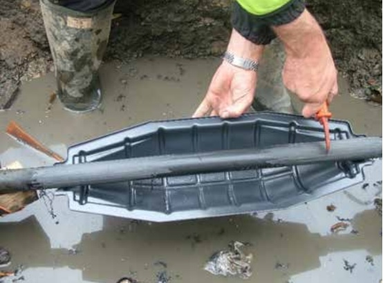
Figure 12 – Not a ‘dry’ environment!
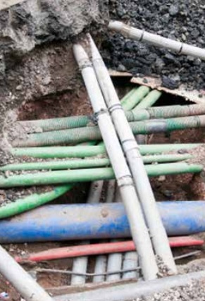
Figure 13 – Crowded road and walk-way services
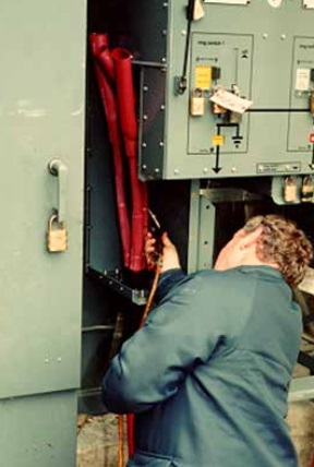
Figure 14 – Crowded road and walk-way services
Further Reading
- Cables | MV Paper Insulated v MV Polymeric Insulated Cables
- First Steps | MV Joints, Jointers & Initial Considerations
- Cable Preparation | Jointing & Terminating Aspects of MV Cable Preparation
- Conductor Connectors | Crimp v Mechanical Connectors with Joints & Terminations
- Earth Bonding | Joints & Terminations & Overheating Prevention
- MV Cable Accessory Technologies | Heat Shrink, Cold Shrink & Push-on
- MV Cables & Causes of MV Cable Failures
- MV Cables | Electric Field & Stress Control
LV, MV & HV Jointing, Earthing, Substation & Electrical Eqpt
Thorne & Derrick International are specialist distributors of LV, MV & HV Cable Installation, Jointing, Duct Sealing, Substation & Electrical Equipment – servicing UK and global businesses involved in cable installations, cable jointing, substation, overhead line and electrical construction at LV, 11kV, 33kV and EHV.
THORNE & DERRICK Product Categories: Duct Seals | Cable Cleats | Cable Glands | Electrical Safety | Arc Flash Protection | Cable Jointing Tools | Cable Pulling | Earthing | Feeder Pillars | Cable Joints LV | Joints & Terminations MV HV
