The Complete Guide to Stokbord Sheets & Cable Covers
For utility contractors and civil engineers, the risk of “striking” buried infrastructure is a daily operational hazard. Whether it’s an 11kV distribution line or a 132kV transmission cable, the consequences of accidental damage are severe, ranging from costly power outages to life-threatening injuries.
Enter Stokbord, the industry-standard solution for heavy-duty underground cable protection.
While Stokbord is widely known as a versatile recycled plastic sheet, in the utilities sector, it serves a specific, critical purpose: providing a high-impact, shatter-proof barrier over MV (Medium Voltage) and HV (High Voltage) cables.
In this guide, we explore why Stokbord has largely replaced concrete and tile tapes, the specifications you need to know (including ENA TS 12-23) and how to choose the right protection for your project available here at Thorne & Derrick.

What is Stokbord?
Stokbord is a heavy-duty protection board manufactured from 100% recycled polyethylene. It is chemically inert, rot-proof, and exceptionally tough.
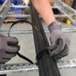
In the context of power distribution, Stokbord is used as a mechanical barrier installed in the trench directly above underground cables. Its primary job is to withstand the impact of hand tools (like spades) and offer significant resistance to mechanical excavators, alerting the operator to the presence of a cable before damage occurs.
Key Characteristics:
-
High Impact Resistance: Unlike concrete, which can crack or shatter, Stokbord absorbs energy and does not splinter.
-
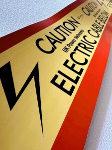
High Visibility: Typically supplied with a red background and a yellow “Caution Electric Cable Below” strip, offering an unmistakable visual warning.
-
Lightweight: A single person can easily handle Stokbord sheets, significantly reducing manual handling risks compared to heavy concrete tiles.
-
DNO Approved: It is the preferred protection material for most UK Distribution Network Operators (DNOs), including UKPN, ENW, and SSE.
Which Stokbord Product Do You Need?
At Thorne & Derrick, we stock the full range of Centriforce Stokbord solutions, catering to voltages from 11kV up to 400kV.
1. Stokbord Cable Covers (The Standard Tile)
This is the traditional format rigid sheets (typically 1 metre in length) that are laid over the cable and interlinked. They are ideal for protecting high-voltage connections where a robust physical barrier is required.
-
Best for: 33kV, 66kV, and 132kV installations.
-
Common Sizes:
-
Specifications: Our stock meets ENA TS 12-23 (Class 1 & 2) and National Grid TS 3.05.07 requirements.
2. Stokbord Drum (The Safety Revolution)
The Stokbord Drum is a game-changer for site safety. Instead of individual tiles, the protection is supplied as a continuous strip on a reel.
-
Safety Benefit: It can be unrolled directly into the trench from the surface. This removes the need for operatives to enter the trench, eliminating confined space risks.
-
Speed: Installation is up to 30x faster than laying individual concrete or plastic tiles.
Alternative: Tapetile
For lower voltage applications (typically 11kV or street lighting) where a heavy rigid board isn’t specified, Tapetile is the standard alternative. It is a flexible, recycled plastic roll that offers visual warning and moderate protection, bridging the gap between simple warning tape and heavy-duty Stokbord.
Technical Specifications & Approvals
When procuring cable protection, “compliance” is the keyword. Using non-compliant materials can lead to project rejection by the DNO.
ENA TS 12-23 Compliance
Most UK utilities require protection that adheres to Energy Network Association Technical Specification 12-23. Stokbord sheets undergo rigorous impact testing to ensure they can withstand strikes without penetrating the cable below.
Dimensions & Thickness
While dimensions vary by DNO specification, standard thickness usually ranges from 6mm to 12mm
-
Length: 1000mm (standard tile)
-
Connection: Tiles feature pre-drilled holes and are supplied with plastic jointing pegs to lock them together, preventing gaps from forming during backfilling
Installation Guide: Best Practices
Correct installation is just as important as the material itself. Always refer to your specific DNO’s engineering standards (e.g., UKPN ECS 02-0019), but the general procedure is as follows:
-
Bedding: The cable should be bedded in fine fill (sand) to prevent damage from stones.
-
Placement: Place the Stokbord cover centrally over the cable.
-
Standard Depth: Typically, the cover is placed 75mm to 150mm above the cable crown. This gap is crucial it ensures that if an excavator bucket hits the board, the force isn’t immediately transferred to the cable.
-
Jointing: Butt the 1-metre tiles together and insert the plastic peg through the pre-drilled holes to secure the joint.
-
Backfill: Carefully backfill over the covers.
-
Warning Tape: For High Voltage installations, an additional Underground Warning Tape is often placed 200-300mm above the Stokbord for an early visual warning.
Why Choose Stokbord Over Concrete?
We frequently get asked if concrete tiles are “better” because they feel heavier. In modern utility construction, the answer is almost always no.
| Feature |
Stokbord® (Recycled Plastic) |
Concrete Tiles |
| Impact Behavior |
Deforms and absorbs shock; shatter-proof. |
Brittle; shatters on impact, creating sharp debris. |
| Weight |
Lightweight; prevents repetitive strain injury. |
Heavy; high risk of manual handling injury. |
| Installation Speed |
Fast (especially with Stokbord Drum). |
Slow; requires heavy lifting and careful placement. |
| Rot/Chemicals |
Inert; 100% rot-proof. |
Can degrade over decades in acidic soils. |
 Protect Your Infrastructures
At Thorne & Derrick, we are leading distributors of Centriforce products, supplying projects across the UK and internationally. Whether you are working on a wind farm connection requiring 132kV Type A covers or a local 11kV diversion using Tapetile, we have the stock and technical expertise to support you.

The Klauke EK30IDML and EKM60ID Revolution
In the demanding world of industrial electrical installation, the goal is always a perfect balance between speed and precision. Traditional crimping methods, while reliable, often introduce an issue: the management of crimping dies. For every cross-section change or conductor class adjustment, an engineer must pause, locate the correct die and perform a physical swap.
Innovative dieless technology, embodied in tools like the Klauke EK30IDML and EKM60ID, is fundamentally changing this workflow. By moving away from fixed-die systems, professionals are now achieving a “gas-tight” connection with more versatility and significantly less downtime.
Whether you are working in a cramped control panel or on a major industrial installation, these tools are designed to think with you.
For more information on the full range see the Klauke Battery Operated Crimping Tools, or browse our range of compatible cable lugs and connectors.
The Game Changer: Dieless Indent Crimping
The standout feature of both the Klauke EK30IDML and its larger sibling, the Klauke EKM60ID, is the dieless indent system.
How it works: Instead of selecting a specific hexagonal die for a specific lug, the tool uses a patented indent profile that automatically adjusts its depth and force based on the resistance of the connector.
-
No more lost dies: No more searching through a heavy kit bag for the right size.
-
Reduced Error: Eliminates the risk of using the wrong die for a specific lug size, a common cause of joint failure.
-
Versatility: Perfectly suited for compacted conductors and fine-stranded conductors (Classes 2, 5, and 6) according to DIN VDE 60228.
EK30IDML: The Panel Builder’s Best Friend

The Klauke EK30IDML is the lightweight champion of the range. Weighing in at just 1.95kg (including battery), it is designed for ergonomic, one-handed operation in tight spaces.
-
Crimping Range: 6mm² to 120mm² (Cu).
-
Crimping Force: 30kN.
-
Battery: 10.8V Li-Ion with a 40-minute charge time.
-
Head Design: Closed, flip-top style and rotatable 350° for maximum accessibility.
EKM60ID: Power & Intelligence for Industrial Scaling
When the job requires larger cross-sections, the Klauke EKM60ID steps up. It features a unique two-stage telescopic cylinder that ensures optimal force is applied regardless of the cable size.
-
Crimping Range: Up to 240mm² (Cu) and 240mm² (Al).
-
Crimping Force: Variable 30kN – 60kN.
-
Smart Technology: Includes Bluetooth connectivity for the Klauke i-press app, allowing you to export crimping reports and verify the quality of every single joint.
-
Safety First: Available in the VDE Orange range, providing 1000V insulation for working in the vicinity of live parts.
Why Professionals use Klauke tools
Working with high-voltage and high-current systems requires trust in your equipment. As a specialist distributor Thorne & Derrick provide not just the tools but the technical expertise to ensure your team is equipped correctly.
Key Benefits of the ML Series:
-
Automatic Retraction: The tool automatically retracts once the correct pressure is reached, ensuring a perfect crimp every time.
-
LED Lighting: Integrated work lights for dark switchgear cabinets.
-
Battery Compatibility: Choose between Bosch or Makita battery platforms to match your existing tool fleet.

Cable cutting and crimping tools manufactured by Klauke are renowned for high-quality, electrical connection tools for cable crimping, cutting and punching – special cable tooling solutions for applications in a range of different sectors.
Klauke tools are used by electrical contractors, cable jointers and linemen for underground cable and overhead conductor crimping and cutting on power, transmission and distribution networks including LV MV & HV systems, 11kV-33kV up to 132kV – this includes battery, hydraulic and ratchet type cable cutters.
Battery operated cable crimping tools are made from the highest quality materials, rust proof and surface finished with a reputation for providing a long service live, consistently delivering safe electrical cable crimping connections for low and high voltage applications, 6-400sqmm. See also: Cable Cutters – Battery Type.

Enhancing Construction Site Safety with the CableSafe Adjustable Kick Plate
Construction site safety isn’t optional, it’s a legal and moral responsibility. With tools, materials and debris is constantly moving across elevated work zones, the risk of dropped objects poses a serious threat to workers below and to the overall success of any project. That’s why choosing effective safety solutions like the CableSafe Adjustable Kick Plate is essential for modern job sites.
Why Drop Prevention Matters on Construction Sites
Objects falling from heights are one of the most common causes of site injuries, equipment damage, and project delays. According to Occupational Safety and Health Administration (OSHA) guidelines, employers must provide protective measures such as toeboards to prevent falling tools and debris.
Dropped object prevention not only protects workers and assets it also helps companies stay compliant with safety standards. Traditional solutions often lack adaptability or durability and can be difficult to install or reuse across multiple projects.

Meet the CableSafe Adjustable Kick Plate
The CableSafe Adjustable Kick Plate is a smart safety solution designed specifically to address the vulnerabilities around platform edges and grated openings. Unlike fixed components, this kick plate offers flexibility and robustness which makes it ideal for a variety of elevated work environments.
Key Benefits:
-
Adjustable & Flexible: The kick plate can be extended to suit different opening sizes, helping you reduce engineering delays and custom fabrication.
-
Durable and Long-Lasting: Built from high-grade aluminium, it’s corrosion-resistant, recyclable, and ready for reuse across many projects.
-
Easy Installation: With a simple installation kit including galvanised J-bolts, spring pins and nuts, workers can set it up without hot work permits.
-
Standards-Compliant: Designed according to OSHA jump protection standards, this kick plate helps platforms meet safety thresholds for toeboard height and strength.
These features make the CableSafe Adjustable Kick Plate an ideal choice for contractors, site managers and safety professionals who are serious about dropped object protection.

Kick Plate Materials & Weatherability
- Strong aluminium frame (thickness 3mm – 012inch)
- Aluminium production is corrosion resistant, recyclable and is greener/environmentally friendly in comparison to plastic alternatives
- Silver coloured, but available in safety yellow for enhanced visibility of Adjustable Kick Plate barrier
- Excellent weather resistance and robustness
- Design in accordance with NEN-EN-ISO 14122
- OSHA approved design (Occupational Safety and Health Administration)
Kick Plate Features & Benefits
- Dropped Object Prevention
- Solid re-usable toeboard
- Lightweight and strong aluminium design
- Universal design for steel grated floors and walkway
Kick Plate Widespread Success
- Standard size universal design
- New design based on heavy industrial experience
- Used in many different applications
- Strong and simple in use
Where to Use Adjustable Kick Plates on Site
This solution excels around:
For permanent or temporary site edge protection, the adjustable kick plate easily integrates with other safety products.
CableSafe Adjustable Kick Plate Installation
The CableSafe Toeboard product is very simple to install and can be easily removed by hand to provide flexible and reusable installation. Available in a universal standard size, the product is design to protect any size opening, simply by increasing the number of Adjustable Kick Plate units to suit the desired size gap/opening. The Adjustable Kick Plates will reduce turnaround time for engineering and design, as well as installation time constructing the grated floors and railings.
- Installed with clamps on grated steel floors
- Supplied with galvanised J-Bolt, spring pin and nuts
- No necessity for welding or hot work
- Not hot work permit or scaffolding required
- Fast and easy to install by hand (no tools required)
Complementary Safety Products to Consider
To build a robust site safety system, combine the adjustable kick plate with these CableSafe solutions:
 Electrical Safety Equipment | CableSafe
Thorne & Derrick stock and supply the complete range of CableSafe Electrical Safety Equipment, including Dropped Object Prevention, such as the Walkway Mat, Guard Net & Safety Nets. CableSafe safety solutions are essential to ensure LV MV HV cable safety and a generally safe working environment in sectors such as, construction, renewable energy, data centres, rail, oil & gas and petrochemical industries.

What Are Cable Cleats?
Cable cleats are mechanical devices used to fix, support, clamp and retain electrical power cables along their routing. They are engineered to restrain cables during short-circuit electromagnetic events, preventing excessive movement that could damage systems or create hazards.
Unlike cable ties, cleats are designed and tested specifically for short-circuit forces they absorb significant mechanical load when needed.
Why Specification Matters
The purpose of specifying cable cleats correctly isn’t just neatness it’s about:
-
Safety under fault conditions
-
Regulatory compliance with standards like IEC 61914
-
Protection of expensive electrical assets
-
Reduced downtime and maintenance costs
Cleats play a role in systems ranging from LV installations in buildings to HV transmission cable routes through substations and tunnels.
Cable Cleat Standards: IEC 61914 & More
When specifying cleats, the first question should be: Does the cleat meet the relevant standards?
IEC 61914 is the international benchmark for cable cleats. It defines test requirements, mechanical properties, and classification methods that ensure a cleat can withstand predicted short-circuit forces.
In addition, installations may require compliance with regional or industry standards such as:
-
BS 7671 (IET Wiring Regulations)
-
Fire performance standards for safety systems
-
Rail and utility specifications
These demand specific cleat ratings and materials.
Key Specification Factors
Cable Diameter & Voltage Class
Choose cleats based on the actual outer diameter (OD) of the cable not just conductor size. Cleats must fit the exact OD for effective restraint.
Additionally, different voltage classes (LV, MV, HV) pose unique force profiles during faults higher voltage systems typically generate stronger electromagnetic forces, demanding more robust cleats.
Mechanical Ratings & Short-Circuit Forces
Cleat manufacturers provide kA ratings which indicate the peak prospective short-circuit current the cleat can withstand, usually defined over specific spacing conditions. Always ensure the cleat’s rating exceeds the system’s calculated fault level.

Cable Cleat Types & Their Uses
Cable cleats come in various designs depending on cable configuration, installation method, and performance needs:
Single Way Cleats
Best for individual power cable runs where standard support and restraint are required. Used across LV to HV systems.
Used to restrain and secure individual low, medium, or high voltage cables, these single way cleats are ideal for flat or spaced arrangements. Common in substations and control panels where single-core or multicore cables are installed.
Trefoil Cleats
Designed for three single-core cables laid in a trefoil (triangular) formation. Trefoil cleats are vital in power distribution systems to control magnetic forces during faults. They’re typically used in high-current circuits or where space is limited.
Quadrafoil Cleats
Specialised cleats used for four single-core cables laid in a quad formation. Common in high-power or parallel circuit applications. Quadrafoil Cable Cleats improve current balancing and electromagnetic performance.
Stackable & No-Bolt Cleats
Stackable cleats allow multiple cleats to be mounted vertically, maximising space in cable ladders or risers. Boltless cleats are fast and tool-free to install ideal for panel boards, data centres and confined space environments.
Fire Resistant Cable Cleats
Designed for applications where fire performance is critical. Fire resistant cleats are made from low smoke zero halogen materials or stainless steel to maintain cable support under extreme heat, flame, or fire exposure.
Typical uses:
triplex Cable Cleats
Triplex cables are three single-core cables twisted together, commonly used in 11kV to 33kV MV HV installations. Due to their spiral shape, standard cleats often can’t securely hold them. To solve this, Triplex cable cleats surrounds are applied to form a circular profile, allowing standard cleats to be fitted safely and effectively.
Material Selection: Strength, Corrosion & Environment
Material choice affects performance and lifespan:
-
Stainless Steel: Exceptional strength and corrosion resistance great for outdoors, marine, or industrial environments.
-
Aluminium: Lightweight with strong mechanical properties, suitable across LV to HV.
-
Polymer / Nylon: Cost-effective, light, fire and UV options available. Ideal for indoor and non-extreme environments.
Consider environmental exposure like chemical presence, temperature extremes, UV exposure and fire risk when selecting materials.
Installation & Spacing Best Practices
Correct installation technique and spacing directly affect performance:
General Steps
-
Position cleats at manufacturer-recommended intervals.
-
Align with cable diameter and configuration.
-
Secure cleat with correct fixings.
-
Tighten to keeper torque without damaging insulation.
Under-tightening risks slippage; over-tightening can distort cable jackets precise torque is crucial.
Spacing depends on cable size and fault current tighter spacing is often needed in high short-circuit scenarios.
Conclusion: Choosing the Right Cable Cleat
Correct specification of cable cleats is a blend of engineering, safety awareness, and standards compliance. By understanding cable layouts, force ratings, materials and installation practices, designers and installers can ensure safe, robust and code-compliant installations across LV, MV and HV applications.
When selecting a cable cleat, consider:
-
Cable Diameter – for proper sizing and fault force calculations of the electrical cable
-
Cable Voltage – LV, MV, or HV applications
-
Construction – armoured or unarmoured
-
Environmental Exposure – fire, corrosion, or chemical resistance
-
Containment Method – tray, ladder, or hanger
Cleats must be IEC 61914 compliant, tested to withstand peak fault forces.

Ellis Patents based in the UK are world leading manufacturers of cable cleats and cable clamps used to clamp and support LV-MV-HV cables – this includes cable support and management products to provide short circuit protection for 600V, 11kV-33kV-66kV and medium/high voltage power cables in single, trefoil or bundled formation up to 400kV.
Cable hangers support single or multiple cables – hangers and cable hooks are available in both galvanised steel and nylon and are used to support horizontal cable routes to building and tunnel structures. A complete range of steel cable hooks are also available compliant with 18th Edition of the IET Wiring Regulations (BS7671) is effective as of January 1, 2019.

Why Liners are Essential in Cable Cleats and Cable Straps: Protecting Cables, Performance, and Safety
When it comes to electrical power installations from LV distribution to MV/HV power networks the small details make a big difference. One element often overlooked by designers and installers is the liner in cable cleats and cable straps. Although seemingly minor, liners play a critical role in cable protection, system reliability, and regulatory compliance, particularly in high-fault environments, as highlighted by manufacturers such as Ellis Patents through extensive testing and field experience.
What is a Cable Cleat?
Cable Cleats are devices used to secure, fix, strap and support electrical power cables in an installation, ensuring safe operation and prevention of damage or injury, specifically in the event of a short circuit. Cable Cleats in Data Centres are ultimately purposed to increase/enhanced safety, organisation, cable protection, containment and ensure optimal performance. Typically, Cable Cleats are designed to be attached to various surfaces, such as ladders, trays, struts, rails, or beams.
What Are Cable Liners?
In the context of cable support hardware, liners are protective layers placed between the cable’s outer sheath and the rigid surface of a cleat or strap. They’re typically made from polymeric or elastomeric materials that cushion and protect the cable while still allowing the cleat to perform its fundamental role — holding cables securely in place.
Linings are engineered to be compatible with a wide range of cable types and environments and are often supplied with specific cleat models where the manufacturer has identified a need for additional protection through compliant or energy-absorbing materials.

The Critical Role of Liners
While cable cleats and straps are designed to secure cables against movement, especially during high-fault conditions, the interface between metal hardware and the cable sheath can be a point of vulnerability if liners are not used. Here’s why liners matter:
1. Prevent Sheath Damage and Ground Faults
Cables are engineered with a protective outer sheath that guards against moisture ingress, abrasion, and environmental stress. Direct contact between bare metal cleats or straps and this sheath particularly under the high forces generated during short circuit events can cause abrasion, deformation, or even cutting through the cable sheath. If the conductor or screen is compromised, a ground fault or insulation failure can occur risking safety and operational performance.
2. Cushion Against Mechanical Stress
During operation, cables undergo thermal expansion and contraction, vibration from mechanical systems, or dynamic loads during electrical faults. Liners act as a cushion that distributes mechanical pressure evenly, helping to absorb these stresses without weakening the cable jacket and maintaining the integrity of the installation over time.
3. Improve Reliability and Lifespan
Even without catastrophic damage, continuous friction, vibration, or contact pressure can cause small micro-abrasions to the cable sheath over time. This accelerates wear and shortens cable service life, leading to more frequent maintenance, replacement costs, and potential failure downtime. Proper liners help mitigate gradual degradation.
4. Support Regulatory and Standard Compliance
International standards such as IEC 61914 which governs the specification and testing of cable cleats emphasise mechanical protection and appropriate cable restraint for safety and compliance. Omitting liners where they’re called for in a specification can lead to non-compliance and additional risk for installers and certifiers, potentially affecting liability and acceptance.
When and Where Liners Are Most Important
Not every cable application requires liners, but they are especially critical in the following scenarios:
-
High-Voltage and Medium-Voltage Cables: Softer insulations or XLPE sheaths can be particularly vulnerable under short circuit forces.
-
Single-Core Power Cables: These often lack internal support, making the external sheath critical for mechanical protection.
-
Soft Sheath Materials: EPR, PVC, or elastomeric jackets can be more easily damaged by point loads.
-
Vibratory or Thermal Cycling Environments: Machinery, transit systems, or industrial settings where cables are subjected to movement or temperature swings.
Best Practices for Liners in Cleat and Strap Installations
To get the best out of liner-equipped support hardware, follow these practices:
Follow Manufacturer Guidance
If the cleat or strap design specifies a liner, always use it do not substitute or omit without consulting technical documentation.
Select the Right Liner Material
Polymeric liners (such as low smoke zero halogen types used in many MV/HV applications) provide not only mechanical protection but also help mitigate smoke and toxic emissions in fire scenarios.
Inspect During Installation
Ensure liners are properly seated and not displaced during tightening. Misaligned liners can cause point loading, defeating the protective intent.
Document Compliance
Keeping installation records that show liners were specified and correctly installed supports quality assurance and regulatory compliance critical on high-stakes power projects.
Small Component, Big Impact
Cables are the lifeblood of electrical power systems and even the most robust power infrastructure is only as reliable as the components that support it. Liners in cable cleats and straps may be small, but they play a critical role in cable protection, system reliability, and safety compliance.
By understanding why liners matter — and applying best practices during specification and installation engineers and installers help ensure safer, longer-lasting and more resilient electrical systems.
 Ellis patents
Ellis Patents based in the UK are world leading manufacturers of cable cleats and cable clamps used to clamp and support LV-MV-HV cables – this includes cable support and management products to provide short circuit protection for 600V, 11kV-33kV-66kV and medium/high voltage power cables in single, trefoil or bundled formation up to 400kV.