The IET Wiring Regulations (BS 7671) now require all new electrical system designs and installations, as well as alterations and additions to existing installations, to be assessed against transient overvoltage risk and, where necessary, protected using Surge Protection Devices (SPDs). Covered in the Furse BS 7671 Guide is the following:
Transient Overvoltage Protection
What are transient overvoltages/surges?
How are transient overvoltages created?
The problem transients overvoltages cause
Why surge protection is required and how to safeguard systems?
Section 443 & 534 of BS 7671 – Protection Against Overvoltage
Risk assessment against transient overvoltages
Compliance to BS EN 62305 & BS 7671
Selection and installation SPDs
The IET Wiring Regulations require all new electrical system designs and installations, as well as alterations and additions to existing installations, to be assessed against transient overvoltage risk and, where necessary, protected using appropriate surge protection measures (in the form of Surge Protection Devices SPDs).
Transient overvoltage protection
Introduction
Based on the IEC 60364 series, the 18th Edition of BS 7671 Wiring regulations covers the electrical installation of buildings including the use of surge protection. The 18th Edition of BS 7671 applies to the design, erection and verification of electrical installations, and also to additions and alterations to existing installations. Existing installations that have been installed in accordance with earlier editions of BS 7671 may not comply with the 18th edition in every respect.
This does not necessarily mean that they are unsafe for continued use or require upgrading.
A key update in the 18th Edition relates to Sections 443 and 534, which concern protection of electrical and electronic systems against transient overvoltages, either as a result of atmospheric origin (lightning) or electrical switching events.
Essentially, the 18th Edition requires all new electrical system designs and installations, as well as alterations and additions to existing installations, to be assessed against transient overvoltage risk and, where necessary, protected using appropriate protection measures (in the form of SPDs).
Within BS 7671
Section 443 defines the criteria for risk assessment against transient overvoltages, considering the supply to the structure, risk factors and rated impulse voltages of equipment.
Section 534 details the selection and installation of SPDs for effective transient overvoltage protection, including SPD Type, performance and co-ordination.
Readers of this guide should be mindful of the need to protect all incoming metallic service lines against the risk of transient overvoltages. BS 7671 provides focussed guidance for the assessment and protection of electrical and electronic equipment intended to be installed on AC mains power supplies.
In order to observe the Ligntning Protection Zone LPZ concept within BS 7671 and BS EN 62305, all other incoming metallic service lines, such as data, signal and telecommunications lines, are also a potential route through which transient overvoltages to damage equipment.
As such all such lines will require appropriate SPDs. BS 7671 clearly points the reader back to BS EN 62305 and BS EN 61643 for specific guidance. This is covered extensively in the Furse guide to BS EN 62305 Protection Against Lightning.
Safeguarding your electrical systems
Why is Transient Overvoltage Protection so Important?
Transient overvoltages are short duration surges in voltage between two or more conductors (L-PE, L-N or N-PE), which can reach up to 6 kV on 230 Vac power lines, and generally result from:
Atmospheric origin (lightning activity through resistive or inductive coupling (see Figures 02 & 03 in pdf), and/or
Electrical switching of inductive loads
Transient overvoltages significantly damage and degrade electronic systems. Outright damage to sensitive electronic systems, such as computers etc, occurs when transient overvoltages between L-PE or N-PE exceed the withstand voltage of the electrical equipment (i.e. above 1.5 kV for Category I equipment to BS 7671 Table 443.2).
Equipment damage leads to unexpected failures and expensive downtime, or risk of fire/electric shock due to arc flash or flashover, if insulation breaks down. Degradation of electronic systems, however, begins at much lower overvoltage levels and can cause data losses, intermittent outages and shorter equipment lifetimes (see Figure 01 see pdf).
Where continuous operation of electronic systems is critical, for example in hospitals, banking and most public services, degradation must be avoided by ensuring these transient overvoltages, which occur between L-N, are limited below the impulse immunity of equipment. This can be calculated as twice the peak operating voltage of the electrical system, if unknown (i.e. approximately 715 V for 230 V systems).
Protection against transient overvoltages can be achieved through installation of a coordinated set of SPDs at appropriate points in the electrical system, in line with BS 7671 Section 534 and the guidance provided in this publication. Selecting SPDs with lower (i.e. better) voltage protection levels (UP) is a critical factor, especially where continuous usage of electronic equipment is essential.
Thorne and Derrick are stockists and suppliers of Furse Earthing and Lightning Protection products. Acquired by the ABB Group, Furse is established as the world leader for earthing and lightning protection.
THORNE & DERRICK
Thorne & Derrick are national distributors of LV, MV & HV Cable Installation, Jointing, Substation & Electrical Equipment – servicing businesses involved in cabling, jointing, substation, earthing, overhead line and electrical construction at LV, 11kV, 33kV, 66kV and EHV. Supplying a complete range of power cable accessories to support the installation and maintenance of low/medium and high voltage power systems:
Choosing Cable Terminations to Reduce Electrical Stress
The following information has been republished with kind permission of 3M Electrical.
Traditional Geometric Stress Cone
This method reduces the electrical stress at the shield discontinuity by extending the shield and gradually increasing the thickness of insulation under the shield. The areas where there is a higher electrical stress receive additional insulation, as shown in Figure 2 below.
GEOMETRIC STRESS CONTROL
Geometric Stress Control – Figure 2
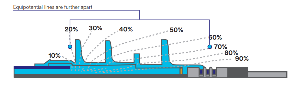
High Dielectric Constant (Hi K) Stress Control
This method lowers the electrical stress at the point of shield discontinuity by refracting the electrical stress. This allows the equipotential lines to spread out along the cable instruction interface. By doing this, the surface stress of the termination is greatly reduced, which improves cable termination performance and life expectancy shown in Figure 3 below:
Thorne & Derrick International are specialist distributors of LV, MV & HV Cable Installation, Jointing, Duct Sealing, Substation & Electrical Equipment – servicing UK and global businesses involved in cable installations, cable jointing, substation, overhead line and electrical construction at LV, 11kV, 33kV and EHV.
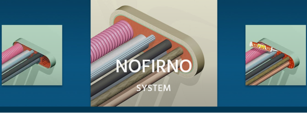
RISE NOFIRNO sleeves and sealant by CSD Systems are made from the highest grade silicone materials, and have a tested service life of over 20 years. Unlike some competitive systems, the RISE NOFIRNO system contains no cheap calcium silicate or mineral wool blankets, which can absorb moisture and cause corrosion of the penetration collar and pipes inside the collar. This problem is referred to as “Corrosion Under Insulation” (CUI).
The CSD NORFIRNO is a Single & Multi Pipe Penetration Sealing System composed of a steel sleeve (length 180 mm or 250 mm) welded or bolted to steel deck or bulkhead, NOFIRNO Filler Sleeves filling the open space between sleeve and pipe – one of the most adaptive systems for sealing straight and angled pipe penetrations and can even accommodate multiple pipe runs, significantly saving in space and weight.
The NOFIRNO system is Type Approved for the harshest ratings for A, H and Jet Fire Class, and is also approved for watertight, gas-tight, blast and shock applications.
RISE NOFIRNO System Features
Approved for harshest fire ratings for pipe penetrations (EN, A, H and Jet Fire class)
Allows substantial movement of the ducted pipes within the conduit
High pressure ratings – designed for gas and/or watertight penetrations
Prevents “Corrosion Under Insulation” (CUI)
Longest service life and best Total Cost of Ownership of any sealing system
NOFIRNO® rubber sleeves and sealant will remain stable and not be consumed by fire
Approved for any combination of cable and/or metallic, GRP or plastic pipes
For insulated copper pipe penetration, RISE/ULTRA shell of thickness 2.5 mm shall cover the insulated pipes over a length of 210 mm.
For Multi-Mix Pipe, RISE/ULTRA strips/sleeves around the plastic pipes.
The penetration is sealed on both ends with a layer of 20 mm NOFIRNO Sealant.
Rise Nofirno Application/Limitation
Single pipe penetrations
Approved for A-0 penetrations for steel, copper and GRP service pipes of following maximum sizes:
Steel: Ø408 mm; Copper. Ø420 mm; GRP: Ø408 mm.
See drawings Nos. R0207E Rev.2 and R0213E Rev.1.
Approved A-0 to A-60 penetrations for insulated (Armaflex AF or equivalent) copper pipes of outside diameter up to Ø54 mm and for Insulated steel pipes up to Ø168 mm.
Maximum sleeve size: Max. Ø273 mm.
See drawings Nos. R0246E Rev.1, R0247E Rev.1, R0248E Rev.1 and R0249 Rev. 0.
Multi-pipe penetrations
Approved A-0 to A-60 single and multi-pipe penetrations for steel/stainless steel pipes up to Ø408 mm, for Cu/CuNi pipes up to Ø420 mm and GRP pipes up to Ø408 mm. Maximum sleeve size: Max. allowable surface area: 2500 cm2 (500 mm x 500 mm). See drawings Nos. N0009E Rev. 2 and N0011E Rev. 2
Approved A-0 to A-60 single and multi-pipe penetrations for steel/stainless steel pipes up to Ø168 mm and for Cu/CuNi pipes up to Ø108 mm.
Maximum sleeve size: Max. allowable surface area: 3000 cm2 (1000 mm x 300 mm). See drawings Nos. N0018E Rev. 2 and N0020E Rev. 1
Approved A-0 multi-pipe penetrations for steel/stainless steel pipes up to Ø219 mm.
Maximum sleeve size: Max. allowable surface area: 1800 cm2 (600 mm x 300 mm).
See drawings Nos. N0045E dated 04.06.12
Multi-Mix pipe + cable penetrations
Approved A-0 to A-60 penetrations for a mix of cables up to Ø105 mm (incl. CLX and LAN cables), steel/stainless steel pipes up to Ø168 mm, for Cu/CuNi pipes up to Ø108 mm and plastic pipes (PVC, PP, PPR, HDPE, PB, PVDF) up to Ø160 mm.
Maximum sleeve size: Max. allowable surface area: 3000cm2 (1000 mm x 300 mm). See drawing No. N0015E Rev.2, N0016E Rev.2 and N0017E Rev. 2.
The installation of the pipe penetration is to be in accordance with the manufacturer installation manual and referenced drawings.
For A-0 divisions, no insulation is needed on the sleeves and the pipes.
Approved for watertight penetrations up to a design pressure of 1.66 bar. Approved for airtight penetrations up to a design pressure of 1.00 bar.
The penetration system is generally not to be used for penetrating boundaries of tanks.
When pipe penetrations is requested to be used in watertight bulkheads on passenger ships and Special
Purpose Ships (SPS), the pipe penetration system has to comply with the requirements given in SOLAS (2009) Ch. II-1 Reg. 13.2.3 c.f. IMO Res. MSC.429(98) Reg. 13.2.3.4. Pipe penetrations passing through watertight bulkheads are subject for separate examination.
Each product is to be supplied with its manual for installation/application and maintenance.
NOFIRNOis one of BEELE Engineering’s ‘rapid cable and pipe sealing systems’ for use on board ships, on offshore pipework installations, in building and construction and other environments where the safety of people and installations has to be guaranteed.
Type Examination Documentation
Test report No. R0209 dated July 2008 from Efectis Netderland BV (TNO).
Test report No. R0325 dated July 2008 from Efectis Netderland BV (TNO).
Test report No. R0556 dated July 2008 from Efectis Netderland BV (TNO).
Test report No. 0303-010 dated 21 March 2003 from Beele Engineering.
Test report No. 0501-039 dated 11 January 2005 from Beele Engineering.
Test report No. 0609-056 dated 19 September 2006 from Beele Engineering.
Test report No. 0712-060 dated 12 January 2007 from Beele Engineering.
Test report No. 0702-061 dated 01 February 2007 from Beele Engineering.
Test report No. 0704-067 dated 18 April 2008 from Beele Engineering.
Test report No. 0706-070 dated 26 June 2008 from Beele Engineering.
Test report No. 0805-080 dated 21 May 2008 from Beele Engineering.
Test report No. 1206-104 dated 05 June 2012 from Beele Engineering.
Pressure test report No. 0203-D056 dated 01 March 2005 from Beele Engineering.
Tests Carried Out Tested according to IMO FTPC Part 3 (IMO Resolution A.754 (18)) and in accordance with IMO 2010 FTP Code Ch. 8.
Marking of Product
The product or packing is to be marked with name and address of manufacturer, type designation, fire technical rating, MED Mark of Conformity and USCG marking if applicable.
Thorne & Derrick are national distributors of LV, MV & HV Cable Installation, Jointing, Substation & Electrical Equipment – servicing businesses involved in cabling, jointing, substation, earthing, overhead line and electrical construction at LV, 11kV, 33kV, 66kV and EHV. Supplying a complete range of power cable accessories to support the installation and maintenance of low/medium and high voltage power systems:
ALUShip Cables Used In Confined Spaces Reducing Installation Times By At Least 40%
ALUminium Cables
Ship Connect System
Republished with the kind permission of Hermod Iverson at Amokabel Norway AS
A new alternative to copper electrical cables is offering shipowners more flexibility and a potential weight reduction of 55% per ampere.
In the race towards more environmentally friendly shipping solutions, reducing a vessel’s weight is a good way to achieve that goal. Swedish cable manufacturing company Amokabel has developed the ALU Ship Connect System, aluminium power cables that offer vessel owners and operators significant benefits.
“Until now, it wasn’t common to use aluminium cables aboard vessels.” comments Amokabel Norway CEO Hermod Iversen. “The main reason for not using the aluminium cables before is that the IEC international standards for shipboard cables only accepted copper cables. After contacting DNV GL, it was agreed that alternative solutions, in this case aluminium cables, might be accepted onboard, provided equivalent technical safety was documented by thorough testing of the cables.”
Testing and qualification of the ALU Ship Connect System was completed in May 2018 and DNV GL subsequently issued the first type approvals for aluminium cables and connectors on vessels.
The amokabel Group is a private own company group consisting of three manufacturing cable companies with subsidiary companies, producing everything from automotive wire to covered conductors.
Significant Savings
Amokabel manufactures various kinds of wires, cables and consumer-packaged products.
The company has a strong focus on quality and minimal environmental impact, and these values are the foundation of the new system.
“The main reason we started looking into the possibilities with aluminium was the environmental aspect. Copper is much heavier and with the new type of vessels, any weight reduction option is worth looking into,” explains Mr Iversen.
“Compared to copper cables, you need more or bigger aluminium cables to get the same electrical load but even taking that into account, you can save up to 55% in weight per ampere by using aluminium cables. That is a big reduction and one that can make a significant impact on the fuel consumption of a vessel. Especially when you measure it over a vessel’s lifetime.”
This weight reduction is particularly attractive for the new type of environmentally-friendly vessel being built, Mr Iversen explains. “When you have a heavy containership, the weight savings are going to make a difference but it will be comparatively small. However, on a battery-powered vessel or a high-speed ferry, the weight reduction is going to have an enormous impact. Every kilo counts on electric vessels.”
Additional Benefits
It is not just the weight reduction that will have a positive impact on the environment. Aluminium is also a more environmentally friendly solution, states Mr Iversen, “The production of the cables is completely green, adding to the environments of using aluminium cable systems. Moreover, the cost of aluminium cables is significantly lower the copper cabling, because the material costs are much lower. Copper is a semi-precious metal. It is not cheap, and it seems a waste to just hide it on the boton of a ship for thirty years. Especially if there is a cheaper, lighter, and cleaner alternative available.”
Successful Installation
Amokabel has spent years developing the project, researching, carrying out tests, and getting certified with, and by DNV GL. The ALU Ship Connect System consists of aluminium cables and copper terminations from Mecatraction in France, “The whole system has been approved by DNV GL. The crimping technology (DBI) has been specially developed by Mecatraction and we worked very closely together to find the best solution for a reliable connection. The crimping technology is based on the combined experience from the aircraft and automotive industry.”
The aluminium power cables of the ALU Ship Connect System are much lighter and easier to install than traditional copper cables.
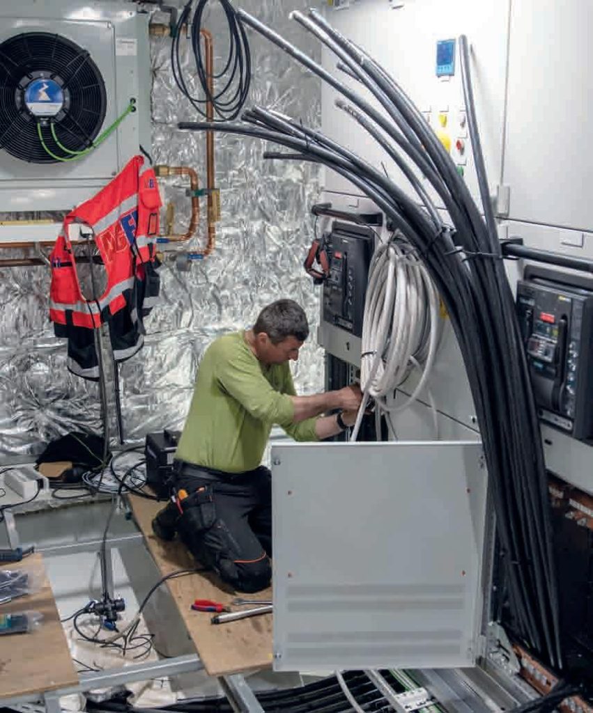
In 2015, Amokabel successfully installed the ALU Ship Connect System on an offshore service vessel in Norway. Another benefit of the aluminium cables became evident during installation. “Because the aluminium cables are so much lighter, they are easier to install,” details Mr Iversen. “It is not easy pulling cables inside a vessel due to the narrow and confined spaces in which they are often placed. I have received several positive comments from installers saying that our ALU cables make their job a lot easier. I would estimate that our cables can reduce installation times by at least 40%.”
Amokabel and DNV GL in March 2018 carried out a joint inspection on board the offshore vessel and found the cables were working perfectly. “There was no change in behaviour or rise in temperature in the cables,” comments Mr Iversen. Successful testing, both in laboratory and on board, showed equivalent safety levels compared with traditional copper cables.
This enabled DNV GL to issue the first type approvals for aluminium shipboard cables and terminations in 2018.” He concludes, “Our biggest challenge now is convincing ship owners and operators of the benefits of the ALU Ship Connect System. Rome wasn’t built in a day, or even a year. But we believe in our product and we believe others will too.”
Marine & Offshore Cable Accessories
THORNE & DERRICK are international distributors of LV, MV & HV Offshore & Marine Cable Installation, Jointing, Substation, Earthing & Electrical Equipment – we supply Joints, Glands, Cleats & Cable Accessories specified for use in harsh and hazardous areas to support the installation of marine and offshore fire resistant cables.
Since 1985, T&D have established an international reputation based on SERVICE | INTEGRITY | TRUST.
DNV is a rigorous approval system for cable accessories including joints, glands and cleats – the DNV approval process assesses all of the evidence offered by the manufacturer and compares it to the requirements of the international standard, IEC61914. Once full compliance is proven DNV Type Approvalis offered.
Contact Thorne & Derrick for further information and customer service – extensive range of DNV Approved Marine & Offshore Cables & Cable Accessories available for delivery to UK and international projects.
LV MV HV – 3.3kV 6.6kV 11kV 33kV
“If you are encountering issues with circulating currents or standing voltages on extended circuit lengths of single core MV cables up to 33kV there is now a solution from Nexans to help control these unwanted and potentially dangerous issues by installing GTSIS.W screen break joints – these cable joints enable you to cross bond the screens of all three circuits in a safe manner that has been Tested and Certified to Cenelec HD 629.1 S2 & IEC 60502-4.
The screen break joints can help control circulating currents on medium voltage power systems and can accommodate MV cables up to 42kV using either compression or mechanical connectors – the joints do not eliminate circulating currents but they sufficiently reduce them to a safer and more manageable level (cable rating wise).
Contact Thorne & Derrick, the Main UK Distributor and Channel Partner for further information today.”
By David Rockall | Business Development Manager at Nexans Power Accessories (UK) Ltd
Screen Break Joints
Utilising heat shrink technology the GTSIS.Wrange of straight joints are compatible with unarmoured single core polymeric insulated cables with copper wire screens (35-1000sqmm) up to 33kV (42kV). Further Information here.
JST | Reliability & Safety at Reduced Cost – a modern generation of MV Heat Shrink Joint has been developed by Nexans for the UK utility and contracting industry – the primary application is for the jointing of 11kV BS7870 Triplex type medium voltage cables. The JTS cable jointing system now provides the most cost-competitive option to power contractors: the cable joints manufactured by Nexans, “The Global Expert in Cables & Cable Systems” are tested in accordance to CENELEC HD629.1.
Thorne & Derrick International are specialist distributors of LV, MV & HV Cable Installation, Jointing, Duct Sealing, Substation & Electrical Equipment – servicing UK and global businesses involved in cable installations, cable jointing, substation, overhead line and electrical construction at LV, 11kV, 33kV and EHV.
INDUSTRIAL LABEL PRINTING SOLUTIONS When clear, durable and professional identification is required across control panels, cable systems, production facilities and industrial installations, print quality, reliability and ease of use are critical. Cembre industrial label printers are designed to support...
HIGH VOLTAGE JUNCTION BOXES & ENCLOSURES When high-voltage power distribution and cable termination are required, safety, enclosure integrity and long-term reliability are critical. HV Junction Boxes and Electrical Enclosures manufactured by Abtech are engineered for the safe distribution, cable termination and protection...


 | New Electrical System Designs & Installations")