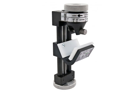
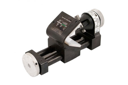
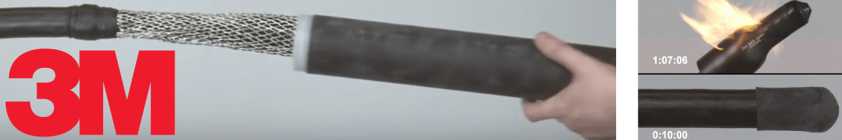
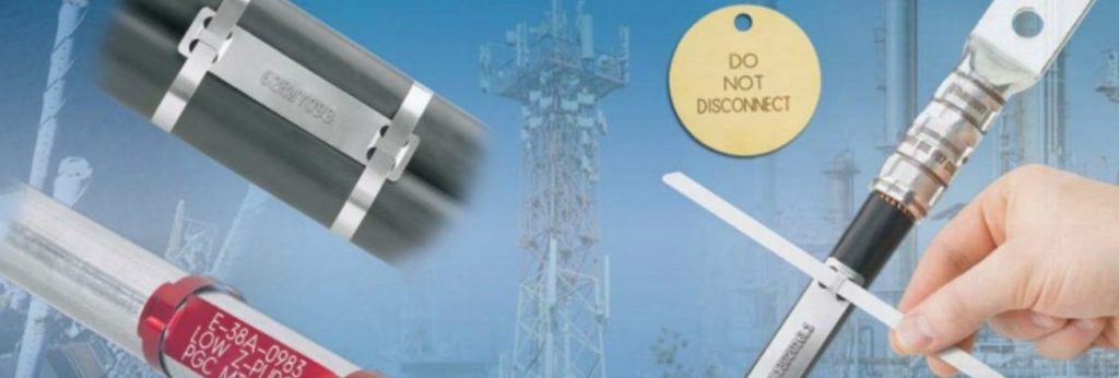
The consac cable jointing tools provides safe and accurate cutting of the sheath without the risk of cutting the live inner conductor – exact cutting depths are achieved when using the different size cutting wheels.
Jointing tools manufactured by Boddingtons are in widespread service throughout the electrical power industry – cable preparation and cable jointers tools are available for use on LV MV HV cables (XLPE, PILC, EPR insulated), waveform, consac, Triplex and utility power cables up to 33kV.
Boddingtons Electrical
Consac Cable Jointing Tools
Features
“T” handle is available to assist the operation of the tool
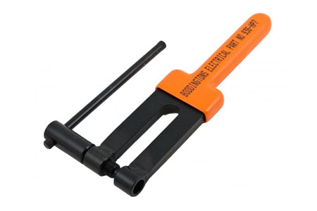
Consac Sheath Punch is available in two sizes – Ø 7 or 10 mm
Complete sheath cutting kit in plastic case available on request
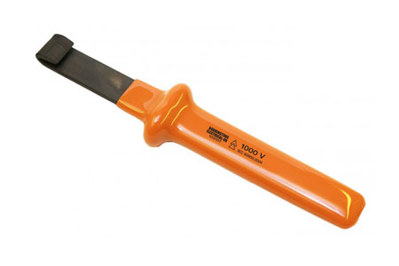
Insulated Sheath Lifters, two types available – all plastic or coated metal
Plastic case to hold MK3 sheath cutter and accessories
700g
Boddingtons 936-HP7
Consac Hole Punch 7mm
700g
Boddingtons 936-HPI0
Consac Hole Punch 10mm
700g
Boddingtons 103107
Insulated Consac Sheath Lifter (metal)
350g
Boddingtons 103108
Insulated Consac Sheath Lifter (all plastic)
50g
IET Forum Post, April 2010
On the British Standards website, BS5593:1978 Specification for impregnated paper-insulated cables with aluminium sheath/neutral conductor and three shaped aluminium phase conductors (CONSAC), 600/1000V for electricity supply was withdrawn by BSI British Standards on 15.12.96.
Waveform – A method of layering wires to form a neutral conductor used in low voltage polymeric insulated mains cables. This is also covered by the following BSI British Standard : BS 7870-3.40:2001 – LV and MV polymeric insulated cables for use by distribution and generation utilities. Specification for distribution cables of rated voltage 0.6/1 kV. XLPE insulated, copper wire waveform concentric cables with solid aluminium conductors
LV Cable Joints (Low Voltage Cables)
Thorne & Derrick stock and distribute LV Joints in Cold Shrink, Heat Shrink or Resin Cast technologies – multicore and multi-pair cable joints are available for immediate backfill and energisation of Low Voltage power, control and instrumentation cables 600V/1000V 3.3kV.
Guest Article by Glen Bate (Panduit Account Manager)
VeriSafe voltage tester
When servicing LV MV HV electrical equipment, workers must comply with safety regulations that require a voltage verification test to validate the absence of voltage.
This process requires strict adherence to prevent accidents and bodily injury, but includes many stages that can be complex and time-consuming when using hand-held portable test instruments.
This paper examines the costs and limitations involved with using a manual absence of voltage tester. It also describes a new technology for the factory floor that automates the process, reducing time, complexity, and costs.
VeriSafeTM by Panduit is the first-of-its-kind voltage tester that determines the absence of voltage with just a push of a button. This revolutionary 2018 NFPA 70E compliant product automates the required six-step testing process in about ten seconds, enabling your plant to operate faster, safer, and more efficiently.
Simplify electrical safety with the superior technology of VeriSafe.
Historical Costs of Checking for Absence of Voltage
Numerous studies exist pertaining to injuries resulting from electric shock and arc flash events. These studies recognise that establishing the economic payoffs of prevention is a critical factor in promoting workplace safety. Besides personal injury, the costs of property and equipment damage need to be considered.
Although estimates vary, studies have shown that the average direct cost of an electrical injury ranges from about US $50,000 to US $80,000′, while the indirect cost can exceed the direct cost by a factor of nearly four2. Direct costs include lost wages or workers’ compensation payments, medical expenditures, and legal expenses.
Indirect costs include:
wages paid during work stoppage
administrative costs related to injury
property damage and repair
training and compensation for replacement workers
lost productivity with less experienced workers
fines related to workplace safety violations
potential increase in absenteeism
decrease in morale
Electrical injuries have one of the highest average workers’ compensation costs, second only to motor vehicle accidents3.
Injuries from contact with exposed wiring, transformers, or other electrical components frequently occur in the workplace and involve construction, installation, maintenance, and repair workers. These injuries are often costly and serious, as demonstrated by the number of days away from work; 51% of workers missed over one week of work due to these injuries, with 40% missing two weeks or more4.5.
Limitations of Using a Handheld Voltage Tester
Verifying the absence of voltage is part of the process to establish an electrically safe work condition. Step 5 of NFPA 70E-2015 Article 120.56 describes this process:
Use an adequately rated test instrument to test each phase conductor or circuit part to verify it is de-energized. Test each phase conductor or circuit part both phase-to-phase and phase-to-ground. Before and after each test, determine that the test instrument is operating satisfactorily through verification on a known voltage source.
This process usually involves a portable, hand-held voltage test instrument. To be effective, it is critical to perform each step of the process in sequence, and it requires taking the necessary precautions, such as the proper use of personal protective equipment (PPE) (Figure 1).
Competent & Authorised Persons
Note Panduit recommend that VeriSafe should be used by competent and authorised people. As VeriSafe is a new and innovative solution to make the Absence of Voltage Testing, we recommend that the people who will use this device, have to be trained in order to understand how it works and how to use it properly.
Please be aware that with this product there is no risk of having hazardous voltage on the indicator module and on the door, as they are isolated from the main power by the isolation module which is located inside the panel. This means that there is less than 5 volts (just enough to power the LEDs on the indicator) present at the device located on the door and used to launch the test procedure.
Figure 1. Absence of Voltage Test Using Handheld Voltage Test Instrument
Adhering to this process prevents electrical injuries, but the process is complex and time consuming. Portable instruments are susceptible to mechanical and electrical failure and misuse by the person using the device. In addition, because the process of using a hand-held tester is dependent on human input, interaction, and interpretation, it is vulnerable to mistakes and errors.
Training Costs
Training on the selection, maintenance, and use of test instruments is crucial as are systems for inspecting and maintaining voltage test instruments. However, training and maintaining the test equipment incur the additional expenses of time and cost.
The Risks of Voltage Testing
Portable Handheld Voltage Detector in Action
Electrical Safety
Traditional Method – Determining absence of voltage with handhled testers presents a risk of exposure to electrical hazards
A disadvantage of implementing a voltage verification test with a hand-held tester is that the person performing it may be exposed to electrical hazards while verifying that the tester is working prior to and after the test, and during the test if the equipment was not de-energized.
With such a significant emphasis on performing work only on de-energized equipment, it is ironic that best practice relies on PPE and exposure to hazards before de-energized work begins. The need for PPE is a significant contributor to the overall time to carry out this process because the worker must first determine the required PPE, then obtain, inspect, dress, and properly store it after use. Additionally, PPE can be misused or not used at all, especially when there are time constraints.
When processes are overly complex or time-consuming, workers tend to become complacent and develop shortcuts as practices become routine. A normalization of deviance—small, gradual deviations from an established practice—may occur over time. With the lack of negative consequences, the lower standard eventually becomes the norm”.
Even when hazards are part of the everyday routine, deviations from a safety procedure can slowly become accepted practice. These deviations are particularly evident when there are time pressures, which is often the case when electrical maintenance causes unplanned or excessive downtime. If either training or enforcement of administrative procedures is lacking, the effectiveness of the procedures will diminish.
A More Efficient Way to Test for Voltage VeriSafeTM Absence of Voltage Tester (AVT)
VeriSafe AVT – Prevents direct exposure to electrical hazards and determines voltage status before equipment is accessed
The VeriSafeTM AVT automates the voltage verification process and is the first AVT tailored for electrical enclosures (Figure 2). By automating this process, the VeriSafeTM AVT features the following:
Tests without exposure to harmful voltages/currents
Self-contained; no additional meters or tools are needed
Built-in pre-/post-verification test
Tests phase-to-phase and phase-to-ground
Automated test sequence
Active indication for absence of voltage
Supports compliance with NFPA 70E-2018 Article 120.5
Rated safety integrity level (SIL) 3 per IEC 61508
The VeriSafeTM AVT is applicable for several applications:
Equipment with a single source of incoming power
High risk associated with access
Equipment with high incident energy
Remote or difficult to access locations — Outdoor, mezzanine, catwalk
Sites with temporary or intermittent power
Equipment with stored electrical energy — VFDs, capacitors, etc.
Equipment frequently serviced by third-party technicians or contractors
Figure 2 VeriSafe AVT
NFPA 70E
One of the major changes to the 2018 edition of NFPA 70E involves the new requirements that allow an installed AVT to be used instead of a hand-held voltage tester. When the VeriSafe– AVT is used in conjunction with a Lockout/Tagout Program, it meets the requirements for the process described in NFPA 70E-2018 Article 120.5:
Exception No. 1: An adequately rated permanently mounted test device shall be permitted to be used to verify the absence of voltage of the conductors or circuit parts at the work location, provided it meets the following requirements:
It is permanently mounted and installed in accordance with the manufacturer’s instructions and tests the conductors and circuit parts at the point of work
It is listed and labeled to verify the absence of voltage
It tests each phase conductor or circuit part both phase-to-phase and phase-to-ground
The test device is verified as operating satisfactorily on any known voltage source before and after verifying the absence of voltage
Figure 3 Comparison of the VeriSafe AVT and Portable Device Testing Methods
VeriSafe AVT – The Safe, Efficient, Accurate Way to Verify
Integrating the VeriSafe™ AVT is a vital improvement to absence of voltage testing. A solid testing method helps create a reliable, safe, cost-effective system that workers can use as needed. The VeriSafe™ AVT verifies the absence of voltage before equipment is accessed, making it easier for qualified electrical workers to determine an electrically safe environment in a fraction of the time required by hand-held portable test instruments.
VeriSafe AVT – Verification Steps
VeriSafe AVT – Safe, Efficeint & Accurate Way To Detect Voltage
VeriSafe Award Winning Panduit Product
B. Campbell and D. A. Dini, Occupational Injuries from Electrical Shock and Arc Flash Events. Quincy, MA: Fire Protection Research Foundation, 2015.
F. A. Manuele, “Accident costs: Rethinking ratios of indirect to direct costs,” Prof. Safety, pp. 39-47, Jan. 2011.
I. B. Horwitz and B. P. McCall, An epidemiological and risk analysis of Virginia workers’ compensation burn claims 1999 to 2002: Identifying and prioritizing preventative workplace interventions,’ Occup. Environ. Med., vol. 49, no. 12, pp. 1376-1385. 2007.
U.S. Department of Labor. Bureau of Labor Statistics census of fatal occupational injuries. [Online]. Available: http://www.bls.gov/iif/oshcfoi1 .htm
Standard for Electrical Safety in the Workplace 2015 Edition, NFPA 70E, 2015.
L. Floyd and B. J. Nenninger, Personnel Safety and Plant Reliability Considerations in the Selection and Use of Voltage Test Instruments: IEEE Transactions on Industry Applications, vol. 33, no. 2, pp 367-373, 1997.
Thorne & Derrick International, based in the UK, are Official Distributors for the Panduit range of cable ties for industrial and hazardous area management of data, telecoms, control, instrumentation and powerLV MV HV cables in industrial and hazardous area industries including oil/gas, petrochemical, rail, renewable, construction and mining/quarrying industries – this includes stainless steel cable ties used to clamp and cleat cables located in medium/high voltage MV HV onshore and offshore substations.
132kV 33kV 11kV DNO Substations
uploaded by Chris Dodds - Sales & Marketing Manager Thorne & Derrick International
A Guide To Cable Sealing By Roxtec
Thorne & Derrick are distributors for Roxtec, the leading manufacturer of sealing solutions for cables and pipes, to protect electricity Transmission & Distribution assets including substations against the potential catastrophic effects water, gas and fire.
The following article discusses Roxtec cable transit products for the sealing of HV single core power cables, multicore cables and earthing arrangements into a substation environment either below ground or at a higher level.
The primary consideration of this specification is to prevent water ingress into the controlled switchroom environment, to assist in maintaining conditions within switchgear operational parameters in accordance with manufacturer’s guidelines and IEC62271-1 2007 / BSEN62271- 1 2008.
This specification also provides protection against pollution from dust, smoke, corrosive and/or flammable gases, vapours and salt in accordance with the same, reducing the potential for equipment failure due to partial discharge.
The Roxtec system also provide a means of secure cable retention under normal loads and fault conditions and/or where the exterior of the building is subject to ground settlement post back-filling of the cable trench. Cable transits also provide ingress protection in both normal and flood conditions and can be installed in running water.
Used for formation of 100mm, 150mm and 200mm cable ducts – see casting guidelines for additional information
Complete sealing solution comprising of a sleeve with an external puddle flange and integrated sealing plate – keeps building dry during and after construction
Cast installation for either new build or retrofit substation applications
IP68 tested and certified to 0.3bar constant water pressure and 1bar catastrophic water pressure. Gas tight to 0.3bar
Roxtec Knock Out Sleeve UG (KOS)
Roxtec Part Number
W (mm)
Accommodates Seal
Accommodates Extension Conduit/ Duct (mm)
Roxtec Article N°
KOS 100/110 UG
180
R 100 UG
RS 100 UG
110
184064
KOS 150/160 UG
230
R 150 UG
RS 150 UG
H3 150 UG
160
184066
KOS 200/200 UG
280
R 200 UG
H3 200 UG
200
184068
Roxtec UG Rubber Seals
Tested and certified to IP68 for constant water pressure to 0.3bar (3m head of water normal conditions) and catastrophic pressure to 1bar (10m head of water flood conditions). Gas tight to 0.3bar
Certified rodent / vermin ingress protection
Cable seals can be installed in running water conditions & retrofit around existing cable installations
Fittings manufactured from 316L stainless steel. Minimum clearance of 3mm between rubber and metal fittings to prevent direct contact between the cable and any metal components
Minimum seal depth 60mm to aid with cable retention. Preventing loss of seal when; movement occurs on the cable due to ground settlement post backfill, the weight of the cables and the flex during operation
Cable retention with a pull force of up to 10,000N and a weight load of up to 1,000kg, depending on size / seal selection
Roxtec RS UG Seal
These cable transits manufactured from Roxylon EPDM rubber with Multi-diameter peelable layers at 1mm increments are designed to seal a single LV MV HV cable between 9-204mm Ø. The unique indicator window allows for a simple check that the Roxtec cable seal has been sufficiently tightened. Fully openable/split system allowing for easier installation / cable positioning.
Roxtec RS UG Seal
Roxtec Part Number
Number of Cables
For Cable / Pipe Ø (mm)
For Aperture Dimension Ø (mm)
Roxtec Article N°
RS 100 UG
1
0+39-63
100-105
167236
RS 100 24-53 UG
1
0+24-53
100-105
186250
RS 125
1
0+55-88
125-130
167638
RS 150 UG woc
1
80-113
150-155
167246
Roxtec H3 UG Seal
These Roxtec H3 cable transits are manufactured from Roxylon EPDM rubber with Multi-diameter peelable layers at 1mm increments designed for use with HV single core cables between 23-68mm Ø in a trefoil formation. The unique indicator window allows for a simple check that the seal has been sufficiently tightened. Fully openable/split system allowing for easier installation / cable positioning.
Designed for entries with multiple LV / Multicore cables, includings control / comms and aux cables. An openable/split round seal used in conjunction with Roxtec RM UG modules.
Roxtec R UG Seal
Roxtec Part Number
Module Packing Space (mm)
For Cable / Pipe Ø (mm)
For Aperture Dimension Ø (mm)
Roxtec Article N°
R 100 UG
60 x 60
Refer to Module Packing Space & Multi diameter Sealing Range of RM UG Modules
100-102
158522
R 150 UG
90 x 90
150-152
150071
R 200 UG
120 x 120
200-202
150075
Roxtec RM UG Modules
Roxtec RM UG sealing modules feature Multi diameter, the Roxtec technology with removable layers so that they can easily be adapted to a wide range of cable sizes. The Roxtec RM UG sealing module is developed to be installed in the Roxtec R UG Seal.
Roxtec RM UG Modules
Roxtec Part Number
Number of Cables
For Cable / Pipe Ø (mm)
Module Packing
Space Dims (mm)
Roxtec Article N°
RM 30 UG
1
0+10-23.5
30 x 30
116837
RM 40 UG
1
0+9.5-31
40 x 40
116865
RM 60 UG
1
0+24-52
60 x 60
116869
RM 90 UG
1
0+48-68
90 x 90
174930
RM 20 UG
1
0+4-13
20 x 20
116871
RM 20w40 UG
2
0+2×4-13
20 x 40
116870
Earthing Arrangements
Flat earth tapes can be sealed using a Roxtec R Seal (AISI 316L) and a water jet cut module in Roxylon EPDM rubber. Note that the Roxtec UGTM pipe or cable sealing system is not suitable for use with braided / twisted earth rope. Solid circular earth bar can be sealed using the standard Roxtec RM modules.
Earthing Arrangements
Roxtec Part Number
Packing Space / Module Dims (mm)
Earth Tape / Cable Dims Ø (mm)
For Aperture Dimension Ø (mm)
Roxtec Article N°
Seals:
R 100 AISI 316L
60 x 60
100-102
R000001001021
R 125 AISI 316L
80 x 80
125-127
R000001251021
R 150 AISI 316L
90 x 90
150-152
R000001501021
R 200 AISI 316L
120 x 120
200-202
R000002001021
Earth Tape Modules:
RM 60/SQ40x4
60 x 60 ET Module
40×4 Copper Tape
118418
RM 60/SQ50x6
60 x 60 ET Module
50×6 Copper Tape
118438
RM 60/SQ50x4
60 x 60 ET Module
50×4 Copper Tape
107067
RM 20w60/31×6
20 x 60 ET Module
31×6 Copper Tape
189962
RM 20w60/40×4
20 x 60 ET Module
40×4 Copper Tape
172809
RM Customised
Customised
Customised Copper Tape
Contact Roxtec
RM Modules/Cable Packing Space:
RM 30
30 x 30 Module
0+10-23.5
RM00100301000
RM 40
40 x 40 Module
0+21.5-34.5
RM00100401000
RM 60
60 x 60 Module
0+28-54
RM00100601000
RM 20
20 x 20 Module
0+4-14.5
RM00100201000
RM 20w40
20 x 40 Module
0+2×3.5-16.5
RM00120401000
RM40 (10-32)
40 x 40 Module
0+9.5-32.5
RM00140101000
IEC62271-1 2007
High-Voltage Switchgear& Controlgear – Part 1: Common Specifications
Note this standard is now withdrawn and superseded by IEC 62271-1:2017 (High-voltage Switchgear & Controlgear – Part 1: Common Specifications for Alternating Current Switchgear & Controlgear). This part of IEC 62271 applies to a.c. switchgear and controlgear designed for indoor and outdoor installation and for operation at service frequencies up to and including 60 Hz on systems having voltages above 1000 V.
This standard applies to all high-voltage switchgear and controlgear except as otherwise specified in the relevant IEC standards for the particular type of switchgear and controlgear. This standard cancels and replaces IEC 60694 published in 1996.
Bespoke Solutions
Contact T&D and together with Roxtec we can discuss design services for seals and customised sealing solutions which fall outside the standard range.
Manufacturing / Quality Approvals
ISO 9001:2008 ISO 14001:2004 certified
Seals tested and certified to IP68
Certified rodent / vermin ingress protection
Complies with recommendations outlined in EA Technology white paper – Humidity Effects in Substations – 2013
Established since 1985, T&D distribute the most extensive range of LV, MV & HV Cable Jointing, Terminating, Pulling & Installation Equipment – contact us today for a competitive quotation.
uploaded by Chris Dodds (Sales & Marketing Manager - Thorne & Derrick International)
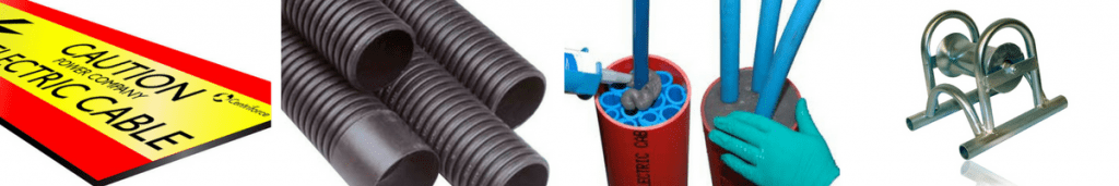
Rail Cable Labels
T&D are Main Distributors for Silver Fox, the UK leading manufacturer of Wire & Cable Labelling Systems for the identification of LV MV HVElectrical, Instrumentation, Security, Data & Telecoms cables in the rail industry.
Key to the specification selection process for rail cable labels is the ability to demonstrate low smoke zero halogen performance in the event of a fire.
LU-1-085 Compliant Cable Labels
for London Underground
LU 1-085 is the current approval document which details the requirements of fire safety materialsto be used on London Underground and Transport for London (TfL).
LU 1-085 includes rigorous fire and safety tests to ensure only the safest materials are installed onto a rail network that transported over 1 billion passengers in 2012.
Compliance of any cable or cable accessory with LU 1-085 is a hallmark of advanced technical specification and product performance.
The stringent performance testing of Silver Fox cable labels has ensured successful installation in high voltage electrical substations where long-term and durable cable labelling is essential on mission-critical power circuits at 11kV and 33kV voltages.
Silver Fox-Flo Tie-on LS0H Cable Labels, Legend Ladder Heatshrink & Heatshrink Roll in Box
Test, Test & Test Some More
Silver Fox cable labels go through rigorous independent testing to ensure their safety and reliability. These tests include:
MIL – STD – 202G Method 106G – Moisture Resistance
MIL – STD – 810F Method 502.4 – Low Temperature -25°C
MIL – STD – 810F Method 502.4 – Low Temperature -40°C
IEC60068 – 2 – 52 Test kb Salt Mist (Cyclic)
H2S Exposure (Sour Ageing)
The Silver Fox Fox-Flo® Tie-On cable labels have also undergone specific testing for:
UL 94 Section 8 ‘Vertical Burning Test’ Rating V0
UV Weathering 8000 hours ISO 4982 Part 3 Method A Cycle 1
IMO FTPC Part 2 – Smoke and Toxicity
IMO FTPC Part 5 – Surface Spread of Flames
All this testing is part of Silver Fox’s continuing resolve to ensure their customers profit from effective and innovative cable labelling products, enabling them to use time productively, whilst also benefiting from high quality and durable solutions.
All Silver Fox Thermal Labels are printed using OneSoftware, One PrinterandOne Ribbon.
Thorne & Derrick stock and distribute an extensive range of 400V-33kV Rail Cable Accessories & Power Distribution Sytems including feeder pillars to contractors undertaking Low Voltage Power Distribution, HV Electrification & Substations, DC Traction & Networks, OLE and Track Feeder Cable Renewals– complete range of Network Rail PADS approved track terminations, cable joints, cable repair and connection products up to 25kV, including 3M Cold Shrink, Pfisterer CONNEX and Nexans Euromold products.
Manufactured & Designed In UK | Short Lead Time | Transformers LV 11kV
uploaded by Chris Dodds - Thorne & Derrick International Sales & Marketing Manager
Transformers
The importance of distribution 11kV transformers as part of electrical infrastructure can not be overstated. As an asset that is always energised, regardless of whether they carry a load, transformers are critical assets and pivotal to ensuring that a safe level of voltage is supplied to businesses across the UK.
It is surprising then to consider that the performance and operation of them has been left offline and unknown apart from when subjected to annual manual inspections, particularly as Industry 4.0 gathers momentum and the UK continues to undergo digitalisation.
Fortunately, the advent of smart transformers has revolutionised this crucial asset and enables companies to access real-time insights into asset performance and operation through remote monitoring capabilities, ultimately enabling a holistic energy management system to be achieved.
The value of such characteristics is apparent in applications such as that of grid tied solar photovoltaic (PV) applications. In these applications, distribution transformers are utilised to directly connect generation from solar PV sources to the grid.
A benefit of grid tied solar (PV) applications is its ability to transform the DC power generated from solar modules into AC power that can be used on the network in a smooth transition without overvoltage.
This transition minimises wasted energy and therefore heightens energy efficiency, whilst the protection against overvoltage allows electrical equipment to continue operating at an optimal level and therefore minimise the risk of premature breakdown and the costs of early repair or replacement.
Additionally, the connection to the network allows those with grid tied solar to take part in the decentralisation of the energy network that forms a key part of the energy transition. This is because the grid connection through a transformer allows for the selling of excess generation to the grid and the asset owner to become what is known as a prosumer – an organisation that both consumes and produces energy.
When the site is utilising solar power, the energy has to be transmitted to the area of consumption, this is when the assets will transform the energy to ensure it is at the correct voltage either to export to the grid or to supply the site. Any interruption caused by a malfunction of a distribution transformer during this process can have significant consequences including wasted solar generation and loss of revenue if during a time of paid export to the grid.
Therefore, the ability to gain valuable insights relating to asset performance and operation can protect against such scenarios by allowing for preventative maintenance to be deployed when anomalous activity is detected, such as a rising temperature of the core.
The real-time responsiveness of the remote monitoring capabilities, such as those found within Powerstar SO-LO a super low loss amorphous core smart transformer with remote monitoring capabilities, enable detailed and easier management of all assets connected to the transformer and can highlight areas of further optimisation. These remote monitoring capabilities can deliver details, 24/7, on grid information, conditional performance data, energy efficiency reports and more from anywhere with a secure internet connection.
Super Low Loss Transformers Up To 11kV By Powerstar SO-LO
This takes on even greater importance in grid tied applications when considering the intensity of PV generators and the role they can play in the security of supply to a site and towards carbon neutrality goals.
Furthermore, smart transformers like Powerstar SO-LO provide greater efficiencies than traditional transformers due to the materials which they use. Instead of using cold rolled grain-oriented (CRGO) silicon steel like traditional distribution transformers, Powerstar SO-LO uses an amorphous alloy core. This is a more flexible material than CRGO and allows for easy magnetisation and demagnetisation to take place which leads to greater efficiencies, with up to 75% lower core losses achievable when using amorphous core compared to CRGO. This greater efficiency further enhances the benefits of grid tied PV.
It is clear that, as the energy transition progresses, the use of onsite generation such as solar PV is likely to become more widespread. However, to obtain the most benefit from onsite generation, particularly given the intermittent and often unreliable nature of renewable sources, it needs to be made as efficient as possible.
Grid tied PV through smart transformers represents a proven and reliable way of enhancing the efficiency of solar PV and maximising the benefits of onsite generation.
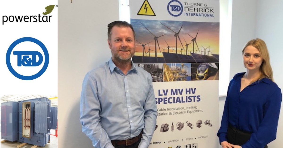
Photo caption: (L-R) Chris Dodds of Thorne & Derrick meeting with Lindsay Brownless (Head of Commercial and Marketing at Powerstar) recently at T&D’s offices in Durham, UK.
Thorne & Derrick distribute the most extensive range of 11kV Cable Installation & Electrical Distribution Equipment to the renewable energy sector – we service UK and international clients working on underground cables, overhead lines, substations and electrical construction at 11kV and up to and EHV transmission and distribution voltages.
klauke ekm60unv – universal cutting, crimping & punching tool The Klauke EKM 60 UNV is a versatile battery powered hydraulic universal tool engineered that can be used as a battery powered cable crimping tool and battery operated cable cutting tools that comes...
INDUSTRIAL LABEL PRINTING SOLUTIONS When clear, durable and professional identification is required across control panels, cable systems, production facilities and industrial installations, print quality, reliability and ease of use are critical. Cembre industrial label printers are designed to support...