MV Jointers
BER Consultancy Services Ltd are a leading provider of Electrical Cable Jointing, Repair & Substation Maintenance Services to the UK utility industry – the Scotland based contractors provides DNO Authorised teams of Jointers, including SPEN for the competent installation of Approved Equipment & MV Cable Accessories up to 33kV including 3M ColdShrink, Nexans Euromold, Pfisterer CONNEX and Tyco Electronics (TE Energy).
The following photographs, republished with the kind permission of Darren Ross (Director | BERC Ltd), demonstrate the workmanship ability and skill-set of their labour force.
To discuss your requirements or to learn more about the provision of LV-HV Cable Installation, Civil Engineering & Groundworks Services from BERC Ltd you can contact Darren on 07501025337.
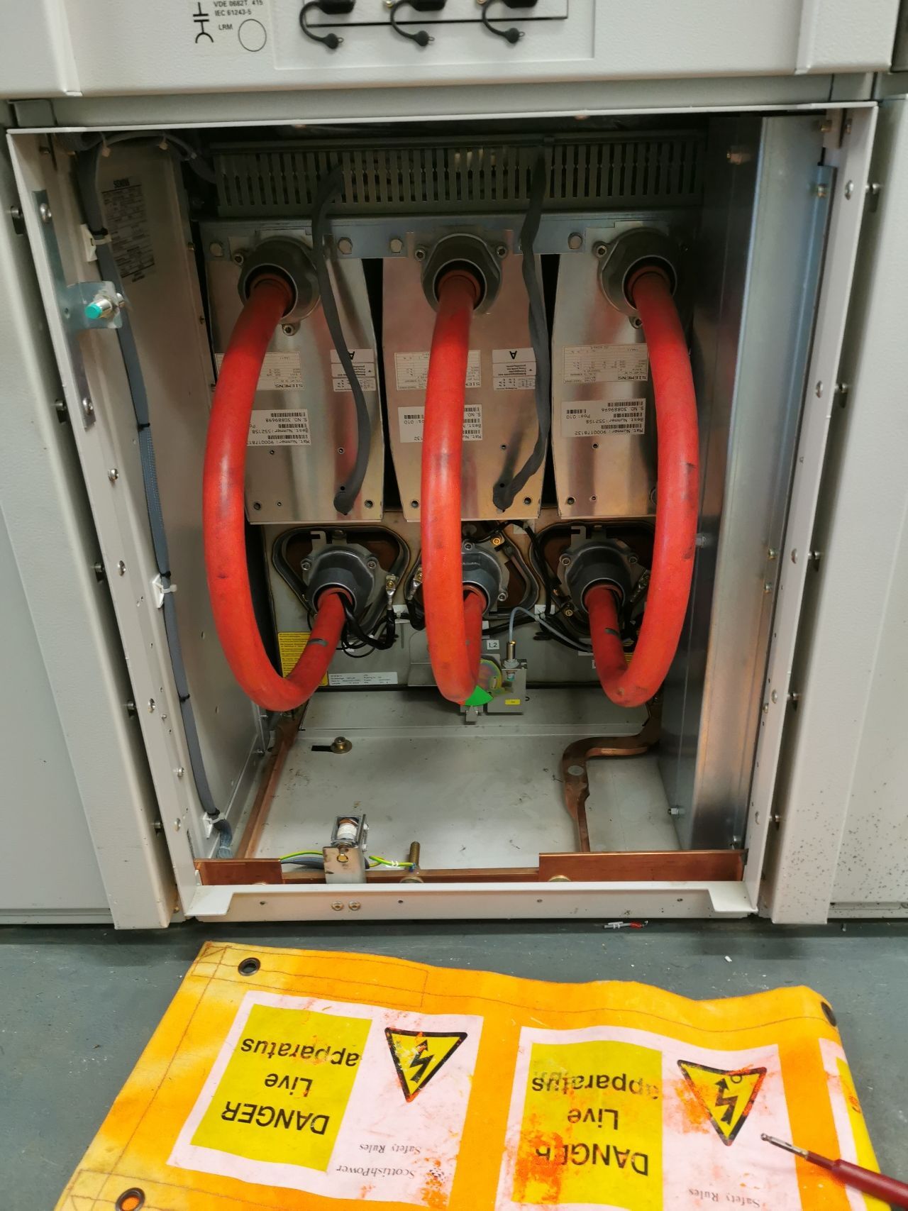
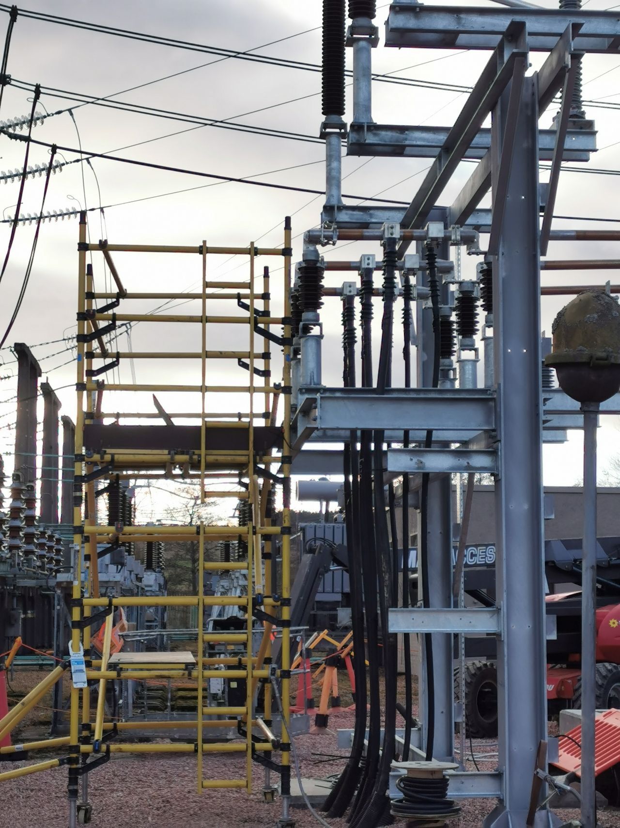
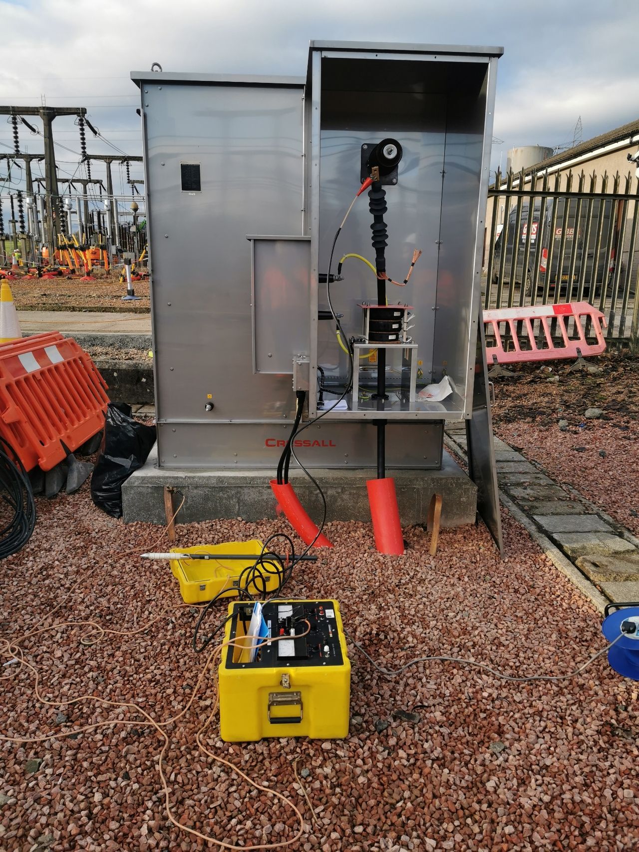
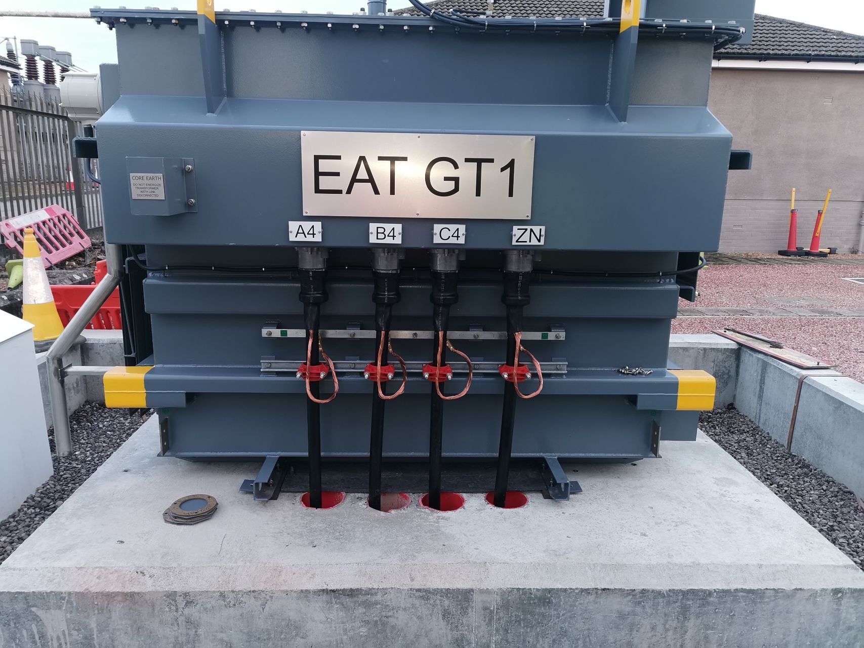
The Jointers used Alroc PG pliers to remove the outer sheath from the medium voltage power cables – a specialist cable jointing tool manufactured by Boddingtons was used to remove the semicon prior to the connection and termination of the 33kV cables (630sqmm) into Siemens switchgear using Pfisterer CONNEX type separable connectors and Sicame terminations onto the outdoor substation busbars. Finally, a circuit of medium voltage 33kV cables (240sqmm) were terminated onto the busbars and connected using MV CONNEX Connectors onto the Auxiliary Transformer and the Neutral Earthing Resistor (NERs) manufactured by Cressall Resistors.

MV Cable Jointers with SPEN Authorisation up to 33kV
SPEN have 30,000 substations (1 for every 100 customers), 40,000km overhead lines and 65,000km underground cables – operating in 3 of the UK’s largest cities (Liverpool, Glasgow & Edinburgh) accounting for 1.6m (43%) of their customers, delivering LV-HV power to significant rural areas (North Wales, Scottish Borders and Dumfries & Galloway).

Jointers blog
Subscribe now to our POWER NEWSLETTER– a monthly email circulation packed with news, projects, videos, technical tips, training information, promotions, webinars, career opportunities and white papers.
Includes access to our popular JOINTERS BLOG with contributions from utility professionals, linesmen and cable jointers working on MV HV EHV cables and overhead lines typically at 11kV, 33kV, 66kV and up to 132kV.
25,000+ Subscribers. ➡ 

Power Cable Accessories
Nexans Power Accessories is the leading European innovator and manufacturer of Low, Medium & High Voltage Cable Accessories as well as connection technology for energy transmission and distribution networks, including both onshore and offshore renewable projects. The Nexans range of Medium Voltage Power Cable Accessories ranged is stocked and supplied in the UK by Thorne & Derrick, contact us for commercial quotations, specification support, product training or to discuss your requirements.
The standard product range of GPH® compression or mechanical connectors and cable lugs is developed and produced as well as customised solutions.
Nexans also manufactures ready-to-install pre-assembled cable lengths and factory tested cable bridges for industrial applications.
Power Cable Accessories for High Voltage Power & IAC Cables 66kV 72.5kV
Catalogue Contents | ↓ Catalogue Download ↓
Nexans
With the brand name EUROMOLD® Nexans Power Accessories is a European market leader for medium voltage cable accessories. T&D offer the entire portfolio of separable connectors for Interfaces A to F in proven EPDM technology with at least 3mm conductive jacket. In this scope, longtime know-how and technological advance was successfully transferred into high voltage applications.
Nexans provide a complete range of cold-shrinkable and slip-on accessories, e.g. pre-moulded terminations and joints for cables and epoxy bushings for transformers and switchgears, up to 170kV.
An extensive range of additional equipment and a variety of dedicated installation training and jointer tooling make Nexans a strong partner in the transmission and distribution of energy.
 |
R909TB/G – EUROMOLD® Tee connector
Interface F
up to 72.5kV, 1250A
U (Um) 60-69 (72.5) kV
Separable tee shape connector designed to connect designed to connect polymeric insulated cable to equipment (transformers, switchgears, ……).
Also connects cable to cable when using the appropriate mating parts.
-Thick conductive EPDM jacket
– Each separable connector is tested for AC withstand and partial discharge prior to leaving the factory
The R909TB/G separable tee connector is type tested acc. to IEC 60840 |
AFN72 – EUROMOLD® Slip-on Termination
For indoor and outdoor use up to 72.5kV
U (Um) 60-69 (72.5) kVDry type, non size sensitive terminations for use indoors, outdoors and exposed to prolonged sunshine and other weather conditions.To connect polymeric insulated cable to equipment and for the outdoor terminating onto overhead lines or bus bars-Its compact and modular design supports the suitability for different pollution levels-All termination housings are tested for AC withstand and partial discharge prior to leaving the factory
The AFN72 slip-on termination is type tested acc. to IEC 60840, and meets the requirements of IEC/TS 60815-3; SPS class d and e. According to IEC 60112: CTI>600 |
 |
 |
72MSJ Single Core Straight Joint
Slip-on technology up to 72.5kV
U (Um) 60-69 (72.5) kV
Non size sensitive slip-on single core straight joint made of silicone, optimised for mechanical connectors. For jointing coper wire screened polymeric cable to be laid in air or directly buried. The product is fully screened and fully submersible.
-All joint bodies are tested for AC withstand and partial discharge prior to leaving the factory
– Protective outer cover made of heat-shrinkable tubes
The slip-on single core straight joint 72MSJ is type tested acc. to IEC 60840. |
Euromold
R909TB/G – EUROMOLD® Tee connector, Interface F
R909PB/G – EUROMOLD® Coupling connector
900SA-CD – EUROMOLD® Surge arrester, Interface F
R900BE/G – EUROMOLD® Bushing extender, Interface F
R900DR-B/G – EUROMOLD® Dead-end receptacle, Interface F
900GP-SBT – EUROMOLD® Grounding plug, Interface F
Possible arrangements Interface F
R900AR-8 / R900AR-12 – EUROMOLD® Equipment bushing, Interface F
Fixings for equipment bushings
AFN72 – EUROMOLD® Slip-on termination for indoor and outdoor use
AFNS72 – EUROMOLD® Slip-on termination with support
FEV72.5 – Outdoor termination with composite insulator
ESC – EUROMOLD® Premoulded EPDM stress cone
Ready to install, pre-assembled cables
72MSJ – Slip-on single core straight joint
72MSJ-x-SB – Sectionalizing slip-on single core straight joint for cross-bonding application
LHV1 – Multitool for cable preparation and installation
➡ See Also | Heat Shrink MONO Terminations MV HV | Heat Shrink JTS Joints MV HV

DOWNLOAD | Distributed in the UK by Thorne & Derrick International


Specialist Distributors to the UK and international Offshore Wind & Renewable industry to provide safe and reliable LV HV Electrical Cable & Power Distribution Systems up to 66kV – we are highly customer responsive and absolutely committed to providing a world-class service.
Contact our UK Power Team for competitive quotations, fast delivery from stock and technical support or training on all LV-HV products.

Stockists & Suppliers | UK & International Projects

Data Centres
Medium Voltage UPSs & Fuel Cells
Original Article By Danel Turk, ABB Global Data Centre Segment Leader
As data centres grow larger, a move from LV to MV is a natural step. Medium voltage (MV) uninterruptible power supply (UPS) and fuel cell technologies have the potential to protect the availability of and provide power to the grid, while saving energy and carbon emissions.
Why are data centre operators embracing green trends?
Increased environmental legislation, coupled with record-high energy prices, puts European operators under pressure. With energy experiencing a supply crisis at a time of high demand, energy-intensive businesses like data centres are eager to take more control over their energy usage. This will help them meet new legislation, maintain power continuity, and earn income from energy markets.
New UPS and fuel cell technologies can provide both power continuity and power to the grid. The technologies also allow the data centre to integrate renewable energy and even generate income by participating in demand and frequency response schemes. Using low-carbon technologies also help to build your reputation as a sustainable business.
Why is the medium-voltage level beneficial for a UPS system?
Data centre UPS systems traditionally operate alongside servers and HVAC equipment at the low-voltage level. However, data centre facilities are becoming larger and demanding more power to gain economies of scale. As power requirements increase, moving to medium voltage is a natural step for UPS systems.
Aside from offering the two primary benefits of increased reliability and reduced costs, medium-voltage systems provide other benefits too.
Operating at 24kV, medium-voltage equipment is significantly more robust than comparable low-voltage systems. A data centre would also require fewer units to meet its power needs. As individual modules, these units are easier to install, operate, and maintain than multiple low-voltage systems spread around the facility. This reduces downtime because more equipment automatically means more risks.
Since the MV UPS operates at a medium-voltage level at the grid connection point, it’s flexible enough to support any data centre loads.

Medium Voltage MV Data Centres

Thorne & Derrick Stockists for Medium Voltage Cable Accessories | Joints | Terminations | Connectors | Tools
MV Approach
The medium-voltage approach also has energy efficiency advantages as it runs lower currents, reducing electrical losses. The latest systems boast efficiency of up to 98 percent because of power conversion equipment that supports power quality continuously without requiring batteries. Evaluated against a rotary UPS, the higher medium voltage efficiency can save up to 4.2 GWh. This saving equates to 1,245 tonnes of CO2 emissions over a 15-year life for a large site.
Added benefits are achievable by using a scalable and modular MV UPS.
For instance, operators can deploy up to ten ABB HiPerGuard units of 2,250 kVA in parallel to handle 22.5 MVA power. In an N+1 configuration, it’s possible to take one system offline while leaving the others in service for ease of maintenance.
Since the MV UPS operates at a medium-voltage level at the grid connection point, it’s flexible enough to support any data centre loads. This flexibility ensures power continuity for servers to remain stable throughout the center by overcoming short outages and power quality concerns.
In contrast, low-voltage UPS capacity can potentially become stranded when power can’t be reassigned elsewhere. This may require additional capital outlay to ensure full coverage of backup power.
Furthermore, operating at the MV level saves on additional capex, as the UPS units can be installed in an electrical room or substation rather than occupying high-value server room space. Such a location makes it ideal for feeding power back into the grid if necessary.
How can fuel cells play a role?
Many of the largest data centre providers actively pursue strategies to reduce or eliminate reliance on diesel generators. For example, Microsoft has committed to ending diesel use by the end of 2030 and is already trialling fuel cells as an alternative.
In 2020, Google announced a commitment to use large batteries instead of diesel gensets at a new site in Belgium. The appeal of fuel cells lies in their potential to provide local backup power and even inject power into the grid during peak demand periods. Fuel cell technology combines materials and chemical science with automation, and protection and control systems, therefore its application requires specialist knowledge from each field.
Importance of Fuel Cells
Fuel cells can be integrated into power systems, for instance deploying 200kW installations to power electric vehicle charging stations where grid power is unavailable. Furthermore, fuel cells provide emergency backup in microgrids and power for telecoms sites at other remote locations.
As a component of microgrids, fuel cells can be combined with other technologies to meet any off-grid or prosumer need
However, for data centres, further investigation needs to take place at the multi-megawatt level. This requires sophisticated development and testing of the interfaces between fuel cells, energy storage systems, electrical switchgear, and control infrastructure. We need an integrated approach to data centre requirements.
As a component of microgrids, fuel cells can be combined with other technologies to meet any off-grid or prosumer need. The latest offerings are available as modular 1 and 3 MW solutions, which are fast to deliver and deploy.

Fuel Cell Station
How can operators use backup capacity to generate income?
Operators with robust infrastructure can earn additional income and offset their costs by selling their excess power back to the grid during peak demand. This can take place through demand response schemes or using a battery energy storage system to support the integration of renewables like wind and solar.
At the end of the day, the data centres own power needs must remain the top priority. Therefore, operators can use MV UPS systems and fuel cells to support their own servers and HVAC systems in the first instance. Only when these needs have been met can spare capacity be used for grid support.

Sealing & Protection of Cables | HVAC Systems, Power & Communications Equipment
THORNE & DERRICK
SPECIALIST ELECTRICAL DISTRIBUTOR
Thorne & Derrick distribute the most extensive range of Cable Installation & Electrical Distribution Equipment to the Power Transmission & Distribution industry in the onshore and offshore wind, solar, rail, oil/gas, data centre, substation battery rooms and utility sectors.
We service UK and international clients working on underground cables, overhead lines, substations and electrical construction at 11kV and up to and EHV transmission and distribution voltages.
- Key Products: MV-HV Cable Joints & Terminations, Cable Cleats, Duct Seals, Cable Transits, Underground Cable Protection, Copper Earth Tapes, Cable Jointing Tools, Feeder Pillars, Cable Ducting, Earthing & Lightning Protection, Electrical Safety, Cable Glands, Arc Flash Protection & Fusegear.
- Distributors for: 3M Cold Shrink, ABB, Alroc, Band-It, Catu, Cembre, Centriforce, CMP, Elastimold, Ellis Patents, Emtelle, Furse, Lucy Zodion, Nexans Euromold, Pfisterer, Polypipe, Prysmian, Roxtec.


GRP Cable Support Systems
Thorne & Derrick together with Mita® can offer an extensive range of GRP cable support solutions that are suitable for any kind of application. As a leading manufacturer of corrosion resistant industrial cable support products, Mita® hereby presents all you need to carry and support each and every kind of electric cable, data, instrumentation, computer or power circuit without any doubt.
Their GRP offer includes a complete industrial cable support systems and trough range specifically designed for harsh and corrosive environments. Whether you are specifying a range of equipment for a major project or buying a selection of components for a simple maintenance installation, their range is unequalled.
What is GRP?
GRP is a composite material formed if glass rovings/shavings together with resin fillers and additives. GRP is the abbreviation of Glass Reinforced Polymer, meaning it is a man-made resin based material which makes it a polymer, reinforced with glass. There are also different acronyms used by different manufacturers, such as FRP and GFRP, however, they all refer to the same type of composite.
The mechanical properties of GRP can vary widely depending on the matrix fibre combination, fillers, veils, reinforcement design, and manufacturing methods.
These properties allow an initial comparison of different types of composites as well as providing a benchmark against which to measure the success of the specific recycling process in achieving acceptable material properties.
How is GRP Manufactured?
GRP is manufactured through a process called pultrusion.

Above you see the glass rovings going into the resin bath, then mats are placed on to these to create the profile first and goes into the die which shapes and cures it in the form of a ladder or tray, and at the end of the line it is cut to the required length.
Pultruded Technology is used whenever the benefits of whole life cost are appreciated and although the process was originally developed in the USA around 50 years ago, low levels of technology have traditionally meant high costs and therefore applications suited mainly to the extreme longevity of the material.
Pultruded Composites consist of four or five main elements:
1) Glass rovings (strands) and mats -approx. 50% by weight
2) Resin – usually Polyester
3) Filler – usually Calcium Carbonate
4) UV Veil and UV additives
5) Fire Retardants as required
Pultruded composites remain largely impervious to corrosion regardless of application. The GRP pultrusion process uses a combination of unidirectional and cross strand glass mat which is resin impregnated and pulled through a hot die to produce a very solid, structurally sound profile.
Pultrusion process gives outstanding structural strength when compared to other composite processing techniques.
GRP Cable Support systems
Production Methods
There are 2 common production methods for GRP cable support systems, which are moulding and lamination (though pultrusion) and do not produce the same results.
Compression Moulding:
Light / Medium Duty
1.Enough structural strength for light and medium duty applications (Low/medium load carrying )
2.Glass content is around 20-25%
3.High filler content
4.Orthothalic resin or Isopthalic resin which might end up having a low fire retardancy
5.Good for indoor applications, its manufacturing results in nice bends and better shape
Lamination through Pultrusion:
Heavy duty
1.High structural strength for heavy duty applications (high load carrying)2.Glass content is around 40-55%
3.Low filler content
4.Isopthalic polyester resin which has a good corrosion/fire performance, and Acrylic resin resulting in better corrosion, fire performance and low smoke/fumes
5.Good for indoor and outdoor applications thanks to the UV surface veil applied during the lamination
The main 2 methods that we come across in GRP cable support manufacturing is pultrusion and moulded manufacturing.
Cable Trough Resin Types
MITA offers 4 main resin types to accommodate the requirements of various industrial applications which can be in chemically aggressive, demanding heated environments.
 |
POLYESTER Type 2 |
Referencing Convention: Ending with PY2
This type of polyester is for general applications, is resistant to
corrosion suitable in industries using heavy chemical and caustic
materials, and resistant to UV light by nature. |
| POLYESTER Type 1 |
Referencing Convention: Ending with PY1
This type of polyester has better fire retardance which makes it
suitable for railway, trackside and any other application requiring UL94
compliance and 5VA classification. |
| POLYESTER Type 1 Carbon Loaded |
Referencing Convention: Ending with PY1C
This type of polyester has anti-static properties as it contains carbon
powder. It, therefore, requires grounding. It is for on-shore and off-shore
oil and gas applications which are classified as explosive environment. |
| MODIFIED ACRYLIC |
Referencing Convention: Ending with MX
This type of polyester has anti-static properties as it contains carbon
powder. It, therefore, requires grounding. It is for on-shore and off-shore
oil and gas applications which are classified as explosive environment. |
Cable Trough Approvals
| Materials |
Standards |
| PY2 |
BS 476 Part 7 |
| BS EN 60695-2-12:2001 |
| PY1 |
UL 94 – V0 |
| UL 94 – 5VA |
| BS EN 60695-2-12:2001 |
| PY1C |
BS476 Part 7 |
| UL94 – V0 |
| UL94 – 5VA |
| NES713 |
| BS60079-0 |
| BS EN 60695-2-12:2001 |
| MX |
BS 476 Part 7 |
| BS 476 Part 6 |
| NES 713 |
| BS 6853 – D8.3 |
| BS 6853 –D8.4 Cat 1B |
| BS 6853 – Annex B2 |
| BS EN ISO 4589-2 |
| BS EN iSO 4589-3 |
| UL 94 V0 |
| UL 94 5VA |
| BS EN ISO 4589-2 |
| BS EN ISO 4589-3 |
| BS EN 60695-2-12:2001 |

| References |
| Wibe full reference |
Wibe quick reference |
| Polyester Class 2 |
PY2 |
| Polyester Class 1 |
PY1 |
| Polyester Class 1 Anti Static |
PY1C |
| Acrylic Class 0+ |
MX |
GRP Cable Support Solutions
Features & Benefits
| Features |
Benefits |
Light weight
Density and weight are significantly lower than steel (70% lighter than steel) with reduced handling requirements. Lightweight in design. |
Health & safety
Reduced risk of staff injuries due to its lightweight, easy to cut, no hot works requirement, no deburring and no sharp edges. |
Compression strength
Despite its lower weight, tension, flexure and compression strength of GRP is almost 20 times that of steel with much greater safety factors. It does not deform permanently under high loads. Slow heat transfer allows for even stronger mechanical resistance. |
Low installation & transport costs
Typically between 30-40% less than steels with easier cutting, drilling and no deburring, painting or earthing. Transportation costs are more economical and the ease of installation ensures that GRP is the more cost effective solution. |
Slow heat transfer & resistant to electromagnetic pulses
It is effective at temperatures between -140oC to +120oC. Resistant to electromagnetic pulses and transfers heat more slowly than steel. Composite materials are excellent insulators having a thermal conductivity 1/60 of a steel product, and do not require earthing. |
Long life & low maintenance
Composites are corrosion resistant and maintenance free. Our GRP products are designed and manufactured to withstand a majority of chemicals & extreme weather – without requiring further maintenance. No rusting, even when exposed to salt spray, H25, acid build up from exhaust gases or brake dust. |
Zero halogen, UV & corrosion resistance
GRP cable support solution is resistant to UV and corrosion, and is zero halogen. It is also available in low smoke classified material. |
Fire performance
GRP is zero halogen. It has low heat and electrical conductivity, and is available in self extinguishing and low smoke material. |
Offer & design
Available in 3m and 6m lengths. Full range of pre-manufactured bends, jointing bays and transitions available for fast installation. Dedicated design facility to support bespoke solutions. |
Installations & modifications are simpler
Mita GRP solutions offer a far easier installation, without the need for painting, earth bonding or special tools. Supplying 6m or 3m lengths reduces amount of couplers required. |
MITA, Schneider Electric + Wibe Group
In 1988, Mita Holdings Ltd was born. In a short while, the company became a leading manufacturer of corrosion resistant industrial cable support products in the UK. In 2005, the company was acquired by Schneider Electric under the name of Mita (UK) Ltd. Mita name continued as a range name under the Schneider Electric brand. Finally, in 2021 the cable support division is acquired by the Swedish group, Storskogen, and is reborn as a stand alone company, Wibe Group.
MitaR is back as a leading brand in GRP cable support solutions. MITA brand is now powered by Wibe Group.
MITA have been supporting customers through their technical journey on choosing the correct product, manufactured from GRP, in cable support applications for almost five decades. MITA are now fully separated operationally from Schneider Electric. They now have a stand alone presence in the UK market with their “Made in UK” products which are fully compliant to the related cable management standards.

MITA are marker-leaders in the manufacture of GRP non-metallic troughing, GRP cable ladders, CABSYS cable trays, ducts, cable support channels and Fibastrut as the brand continues to lead the industry towards a sustainable future for a wide range of low (LV), medium (MV) and high voltage (HV) cable installation applications.
RAIL CABLE ACCESSORIES, ELECTRIFICATION

& INSTALLATION EQUIPMENT
Thorne & Derrick supply an extensive range of 400V-33kV Rail Cable Accessories & Power Distribution Systems including feeder pillars to contractors undertaking Low Voltage Power Distribution, HV Electrification & Substations, DC Traction & Networks, OLE and Track Feeder Cable Renewals – a complete range of Network Rail PADS approved track terminations, cable joints, cable repair and connection products up to 25kV, including 3M Cold Shrink, Pfisterer CONNEX and Nexans Euromold products.
Full range of Cable Pulling Equipment & Products to ensure safe and efficient of rail cables in to cable ducts and containment infrastructure including cable troughs.

Earthing System Testing
In theory, earthing system testing is very simple, but in practice somewhat more complicated. Recently our development engineers Matthew Lee and Steven Preedy asked the question…Are we really testing R, Z or something else?
The authors have investigated and tested a range of scenarios and instruments and sought to be definitive. This article presents their methods, results, and conclusions.
In theory, earthing system testing is very simple. One simply applies a voltage between the system under test and a remote earth electrode, measure the current, measure the voltage ‘across’ the system under test, and divide it by the current.
In practice earthing system testing is somewhat more complicated. Questions often arise regarding the practicalities of testing, including:
- How do you establish a suitable remote earth?
- What type of voltage do you apply?
- How much current flow do you need?
- Where & how specifically do you measure the voltage?
- How do you measure both reliably?
- How do you detect and reject (or correct for) electrical noise, both AC & DC?
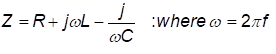
These are all important questions, and whilst many have reasonable answers, one question remains in dispute: If you test with an applied voltage that has both DC & AC characteristics, do you measure a resistance or an impedance?
The IEEE committee revising Std 81, amongst others, have wrestled with this question, and currently, there is no consensus. To answer the question “Are we really testing R, Z or something else?” the authors have investigated and tested a range of scenarios and instruments and sought to be definitive. This article presents their methods, results, and conclusions.

Safearth consultants in the field performing soil resistivity testing
Why are we asking this question and what are we testing?
For an earthing system to be effective, its performance needs to be adequate for the power system attached to it and all the factors that affect its performance need to be considered. The performance of the earthing system is entirely dependent of the ground in which it is placed.
The soil composition, existing infrastructure and mineral/moisture content all affect the apparent resistivity of the soil and thereby the performance of the earthing system. To assess the performance of an earthing system requires tests of parameters associated with or affecting that performance, including soil resistivity, EPR, resistance of earth grid, loop impedance, and continuity.
How Are We Testing?
To measure each of the aforementioned parameters current must be injected into the earthing system and/or the surrounding soil and the response measured. The injected current can be either a ‘Switched DC’ or an ‘AC current’ injection.
In both methods, the current is known, and voltage is measured. The question we are investigating here is “for a switched DC injection how should the measured voltage be interpreted?”
How do switched DC instruments work?
Switched DC instruments inject a known current in the form of a switched current square wave into the system. The voltage measurement is conducted at a specific part of the injected waveform, some in the middle and some at the end of the waveform.
Measurements are taken at these points to remove the effect of test lead coupling. With a known current and a measured voltage, ohms law can be applied – (R=V/I) to deduce the measured resistance.
What Happens When It Gets Complex?
Reactive elements in the system introduce complexity to an earthing system’s response. When measuring a complex system, the presence of reactive elements can affect the measured result. These reactive elements come from auxiliary paths such as overhead earth wires, buried conductors and cable screens.

Figure 1 Resistance Measurement of Complex Earthing System
How we showed the measurement can include errors
Using two switched DC instruments, we set up an equivalent circuit that would allow us to change real and reactive components. From this we could simulate how the measurement waveforms become distorted as the ratio of L to R increases and what the resistance tester records as the apparent resistance.
The setup was measured with zero inductance initially to establish a control value. All other measurements with inductance were compared to the control value.
What happens when we have reactive elements?
Based on one theory the behaviour of reactive elements is just …
The reality is that high inductance reacts to the injected switched DC current such that the resulting voltage waveforms become distorted, as shown in Fig 3. The distortion in the measured voltage waveforms create error within the measured resistance.
The result is that the magnitude of the measurement is larger than the resistive component of the circuit and is not indicative of the system under test. If the reactive element is small in relation to the real resistance, there exists a plateau near the falling edge of the received signal. This plateau is the real magnitude and contains little to no error being uninfluenced by the reactive element. By using the plateau of the signal, the measurement can be effectively used to calculate the real resistive element.

Figure 3 Measured voltage waveforms in high inductance circuits
How does impedance affect the results?
What we found was that the effects of inductance on measurement accuracy and reliability are dependent on the ratio of R to L, with the following features:
- Large R values negate low L values;
- Large L values dominate low R values;
- The L/R ratio does not imply the associated error;
- The error becomes significant when the millihenry range of inductance is reached; and
- The lower the frequency the more time for reactive elements to dissipate, allowing more time for a plateau to be reached.
Are we measuring an impedance with switched DC?
The short answer is no. Switched DC current injection measures the voltage at a certain point of the waveform and applies Ohm’s Law (R=V/I). It cannot measure a phase angle and thus cannot get a phase shift to deduce impedance.
The long answer is, it’s complicated. Due to the truncated measurement window technique used specifically by these testers, quantifying the amount of reactive information captured in that sample window is not trivial. In addition to this, the result is not a linear increase in error for a linear increase in inductance.
Does It Matter?
Typically, switched DC measuring instruments are reliable for individual electrodes, groups of electrodes and small to medium sized grids with no or minimal interconnecting paths. When testing on large grids or grids with multiple auxiliary paths, the effect of reactive elements can be observed by changing the injected frequency and noting that the recorded resistance changes with frequency.

Safearth engineers in the field performing soil resistivity testing
We ask again…. Are we really testing R, Z or something else?
These instruments are suitable for testing a resistance until they cross an implicit R/L ratio threshold. Past this threshold it appears that the inductive (L) component affects the measurement sufficiently such that substantial error can be observed. This measurement is relative to the circuit under test, but the reactive element cannot be deduced.
Through this investigation, it was found that 3 & 4 terminal switched-DC testers are always attempting to measure a resistance. When significant reactive elements are introduced into the circuit under test, the instrument ends up reading something else as it is trying to calculate resistance despite the measured waveform being distorted by the presence of the reactive elements. This implies that it is not an impedance being measured, the value that is calculated is only relevant to that specific circuit.
A way to check if there are reactive elements in the circuit is to change the frequency of the square wave. If the value doesn’t change, then it is dominantly resistive, and the measured estimate is valid. However, if the measured value changes significantly, there is enough of a reactive element in the circuit under test to affect the result and it must be considered an invalid measurement.
This article comes from the perspective of Safearth development engineers Matthew Lee and Steven Preedy who research, design, develop and manufacture our suite of Safearth earthing system test instruments. Their consultants regularly use our earthing testing equipment in the field in Australia and overseas. Original article can be found here – https://www.safearth.com/are-we-really-testing-r-z-or-something-else/
About Safearth

Safearth is a specialist electrical engineering group providing world-recognised expertise in safe power earthing systems.
Safearth delivers comprehensive earthing solutions and management to safeguard people and infrastructure from electrical faults and lightning. Since being established more than 30 years ago, we’ve designed and tested thousands of earthing systems for high voltage installations, for power utilities, mines, oil & gas sites, and other industries.
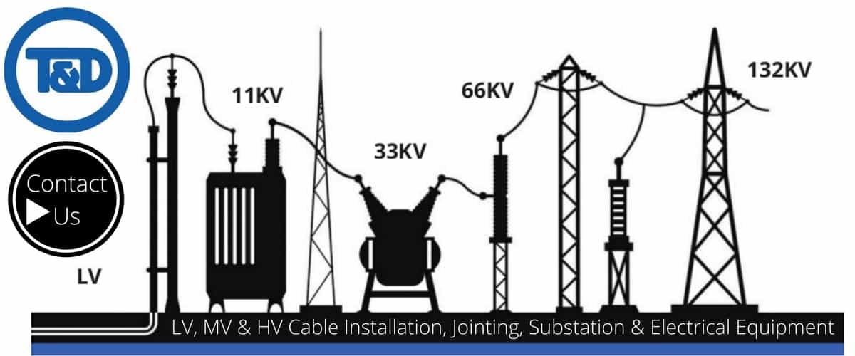
THORNE & DERRICK are national distributors of LV, MV & HV Cable Installation, Jointing, Duct Sealing, Substation & Electrical Equipment – we service UK and global businesses involved in cable installations, cable jointing, substation earthing, overhead line and electrical construction at LV, 11kV, 33kV and EHV.
Since 1985, T&D have established an international reputation based on SERVICE | INTEGRITY | TRUST.
Contact us for 3M Electrical, ABB, Alroc, AN Wallis, CATU Electrical, Cembre, Centriforce, CMP, CSD, Elastimold, Ellis Patents, Emtelle, Euromold, Filoform , Furse, Lucy Electric & Zodion, Nexans, Pfisterer, Polypipe, Prysmian, Roxtec, Sicame, WT Henley.