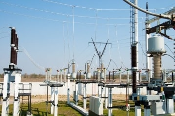
In this article, Castell discusses how trapped key interlocking is implemented within switchgear control whilst maintaining system integrity.
Factors such as aging infrastructure, technological advancements, lack of investment, demands for cleaner and reliable ever-present energy, have significantly altered the scenery of the energy sector with switchgear systems becoming increasingly complex.
Switchgear systems can utilise or involve several incomers, earthing systems, making the integration of HV (High Voltage), MV (Medium Voltage), LV (Low Voltage) or switching incomers and common supply busbars potentially complicated. This not only increases the potential level of complexity but also the need for robust and reliable safety systems to ensure personnel safety, electrical equipment protection and its correct, safe mode of operation at all time.
The safe and effective operation of switchgear can be achieved through a sequential release system which sets out a process that must be followed removing the need for reliance on work instructions alone.
The system designer should consider the operational processes in conjunction with the safe state of equipment. A challenge with switchgear if one or more supplies shuts down due to an overload or power failure or for planned maintenance purposes is that the remaining supplies will have to carry the load. Therefore, the sequence of operation must be controlled in such a way to ensure that power is maintained, the shutting down of the remaining supplies due to overload is avoided and the collapse of the entire system is prevented.
Trapped key interlocking constitutes an effective way to control the sequential operation of switchgear systems. A trapped key interlocking system can ensure a process is followed and cannot be circumvented. The transfer of a key ensures that wherever personnel find themselves, in either starting or shutting down operations, they can be assured that they are safe through the control of switchgear isolation.
Management of complex switchgear systems can be controlled through a blanking system. The blanking system means that some of the symbols on the busbar locks have a part coded lock which denotes it can be isolated by more than one of the keys forming the switchgear system.
For instance, if we part coded a lock to A ‘Blank’ we can use any 2-character symbol keys with a prefix of ‘A’ to operate the lock (see below for more examples). The system’s integrity is maintained by the design of the nomenclature chosen for the incomer and busbars.
This means the open and closing operation of the switchgear can be controlled with less locks and keys. Blanking systems, although not suitable for every switchgear application, offer some significant advantages. More specifically, they remove the need for excess keys and additional key exchange boxes allowing for a simpler interlocking system. Implemented correctly, they can also provide cost and time saving benefits.
Applications
Applications for incomer and busbar interlocking or incomer, generator and busbar interlocking are used in any environment where there is a demand for reliable energy sources such as data centres or building management services like factories, hospitals, airports, rail and stadiums.
Example 1: Incomer and Busbar Interlocking
This system requires five locks and three keys. In the normal operation the keys are trapped in the incomers in the closed position and both bus couplers are open.
The symbol sequence will allow appropriate incomers to be open allowing the key to be released, transferred and inserted and trapped to the associated bus coupler allowing it to be closed. The symbols used here are AA, AB and BB for the Incomers and A_ (A BLANK) and _B (BLANK B) for the bus couplers.
Example 2: Incomer and Busbar Interlocking
This system will require four locks and two keys. The keys are trapped in incomer 1 and 2 with the switches in the closed position.
Both the bus coupler and incomer 3 open.
The symbol sequence will only allow incomer 3 or the bus coupler to be closed after the appropriate key has been released, transferred and inserted into the bus coupler or incomer three lock.
The system ensures that only two incomers are supplying at any time.
The symbols used here are AA and AB for the incomers and A_ (A BLANK) for the bus coupler.
Example 3: Incomer, Generator and Busbar Interlocking
The normal operation is the two incomers are closed with bus coupler and generator are both open. The symbol arrangement using key symbols AA, AB, A_ (A Blank) on locks with just keys AA AB will ensure safe switching operation.
It will not be possible to have incomer 2 and generator closed at the same time to avoid paralleling.
The symbols used here are AA and AB for the incomers and A_ (A BLANK) for the bus coupler.
Designing an interlocking system
The design of an interlocking system is a process that must be carefully undertaken. A good interlocking scheme requires all risks and operational procedures are considered in advance ensuring integrity. This can proactively address how the system will respond in both operational and failure modesalong with routine maintenance.
An interlocking system will set out the process and steps that must be followed to ensure personnel cannot access potentially dangerous areas. When maintenance activities are being performed, trapped key interlocking systems can ensure that the switchgear system is always put in a safe state. Trapped key also ensures that the system operates efficiently and there is no chance of, for example, switching two incoming feeds on to a common busbar significantly reducing risks (such as fire, arc flash) as well as the possibility of equipment damage.
Conclusion
Complicated switchgear systems need to have a robust management system to protect personal and machinery. Designed correctly, an interlocking scheme can contribute to eliminating human error on site while permitting safe access to electrical equipment. Integration of older equipment with new switchgear can be a challenge, trapped key interlocking allows for the safe integrating with OEM switchgear, ensuring safe site operations and negating the need for complicated controls.
Castell have been delivering safety solutions for switchgear since 1922. Working closely with original equipment manufacturers (OEMs) has enabled Castell to produce interlocks designed specifically for use on the leading manufacturers own breakers, isolators, disconnectors and earth mechanisms. Castell offer a range of isolation products for switchgear applications.
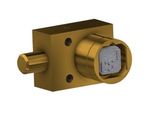
The FS lock range can perform in the harshest environments using figure symbols as the unique identifiers enables defining a unique blanking system which allows for easier use of switchgear within the integrity of the trapped key system. FS locks can be incorporated into all Castell product for isolation equipment. Where isolation requires an un–masterable solution on switchgear, Castell Q range offers the ability to uniquely code locks to site requirements and as with the FS range, the Q range of locks can be used on all Castell isolation products.
HazardEx supports hazardous area and process industry professionals and are the leading technical authority on explosive atmospheres – protecting people and plant through a series of Exhibitions, Conferences, Workshops, Seminars and Webinars across the globe.
HazardEx is where industry leaders meet to discuss and engage to ensure workplace and worker safety in potentially explosive atmospheres.
T&D are Specialist Distributors of LV MV HV Cable Installation, Jointing, Substation & Electrical Equipment– we supply companies in the onshore and offshore wind, solar, rail, oil/gas, data centre, battery storage and utility sectors with products to enable the energisation, operation and maintenance of underground cables and overhead lines.
Safe & Easy Live Line Working at Low Voltage Networks & Cables
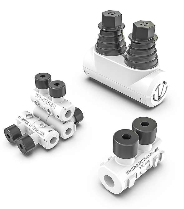
Live line working is increasingly essential in low voltage networks. Bolted connectors used for this purpose should be easy to install and ensure the best possible occupational safety. The LV piercing connector family from PFISTERER has been developed to meet today’s practical requirements. Durable contacts come as standard, and have been a PFISTERER core competence for nearly 100 years.
Conductor does not have to be stripped
Insulation piercing connectors connect and make electrical contact with conductor ends, whatever the conductor cross-section, type and insulation. Because they pierce the insulation during installation, preparatory work on the conductor, such as stripping or brushing the contact area, is eliminated when live working.
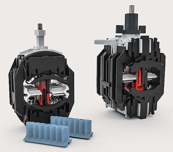
The shear bolts on insulation piercing connectors LV are based on patented SICON technology. The electrical connector bolts are equipped with a piercing system that reliably penetrates the conductor insulation during installation by the cable jointer. A rotatable disc at the base of the bolt prevents damage to individual strands and ensures the correct contact force for all conductor materials.
New installations or repairs LV piercing connectors easily and safely connect all low voltage cables – even under voltage
Good occupational safety
The insulating body and plastic cover caps provide IP2X protection against finger contact in accordance with EN 60529. On type 3 and above, plastic flaps prevent inadvertent contact with the inside of the conductor channel. The elastomer insert ensures protection against contact after the bolts shear off.
Low shear off torque
The shear off bolts are tightened using standard tools. Once the optimal contact force is reached, the bolt gently breaks away at a torque of between 2.5 and 27 Nm, depending on the type. This prevents common installation errors and makes live line working much safer.
Compact and well designed
Once installed, the small size of LV piercing connectors makes subsequent work easier. Compact cable joints with cast resin mean that fewer resources are needed for the final installation. The connectors can be placed close to each other without any further accessories.
Type 1 and 2 are equipped with a push together system: multiple connectors can be joined together to form a compact unit. With type 3 to 5, the elimination of the cover caps ensures the smallest possible dimensions.
Connector Benefits
Insulation does not have to be stripped from individual conductors
Easy, safe installation – ideal for live line working
Shear-off bolts prevent installation errors
IP2X protection against electrical hazards
Consistent operational reliability, according to IEC 61238-1 Class A
Thorne & Derrick stock and distribute PFISTERER CONNEX Connectors for medium / high voltage cable connection and termination to electrical systems up to 33kV – we provide competitive prices for PFISTERER CONNEX connectors used to terminate and connect polymeric insulated MV-HV cables into gas insulated switchgear and electrical equipment from extensive UK stocks.
Thorne & Derrick are national distributors of LV, MV & HV Cable Installation, Jointing, Substation & Electrical Equipment – servicing businesses involved in cabling, jointing, substation, earthing, overhead line and electrical construction at LV, 11kV, 33kV, 66kV and EHV. Supplying a complete range of power cable accessories to support the installation and maintenance of low/medium and high voltage cable systems:
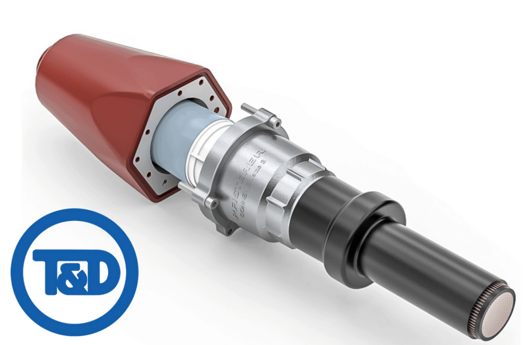
The SEANEX inner cone solution is an offshore variant of the successful Connex HV connection system that is specially adapted for 66kV inter-array cabling.
In modern substation engineering, cable connections are increasingly implemented using screw technology. The 2DIREKT terminal clamp by PFISTERER is a solution for connections to transformers and busbars.
2DIREKT combines simple installation with a compact, cost-effective design.
Almost 100 years of contact technology experience and innovations for easy and safe installation are in every 2DIREKT terminal block.
Connects directly to transformer bushing or busbar
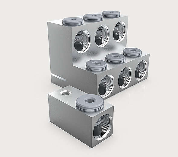
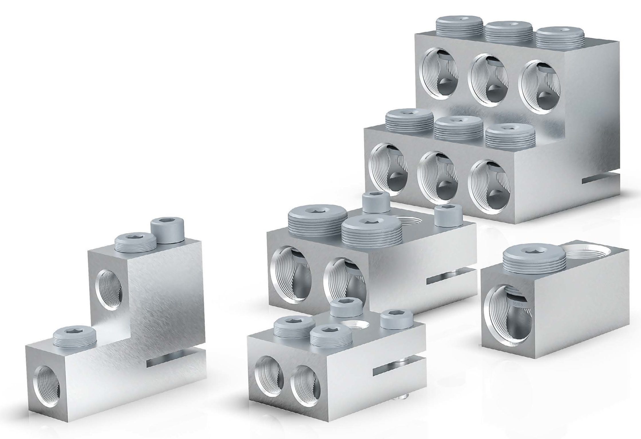
The 2DIREKT clamp is connected directly to the distribution transformer. It screws onto the transformer bushing and is secured via a clamping groove and clamping screw. This reduces the amount of installation work and the risk of connection errors.
No cable lugs have to pressed on, and no wire-end ferrules have to be fitted. There are fewer points of contact and transition resistance is minimised.
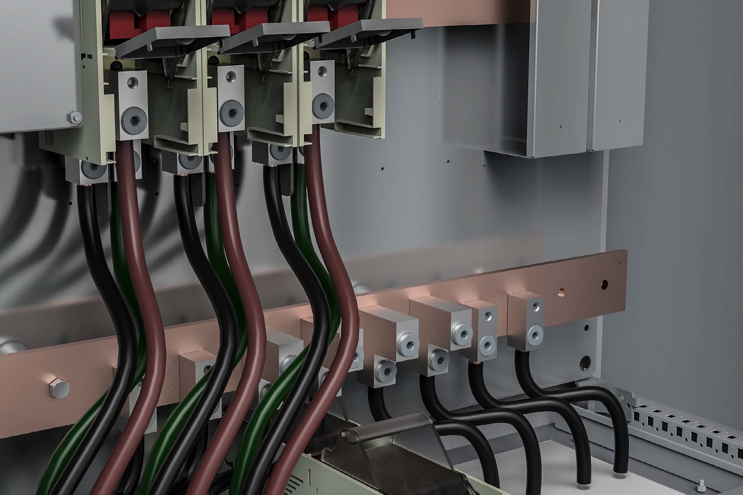
The 2DIREKT A version allows cables to be connected directly to busbars. Fine grooves on the underside of the clamp enables connection without additional components directly on the busbar.
The 2DIREKT is connected directly to the distribution transformer, making palm terminals, cable lugs, sleeves and nuts redundant
Safety during installation and operation
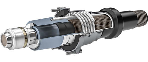
The patented conductor connection system eliminates damage to the conductor during installation. A rotating plate on the base of the clamping bolt prevents individual fine-wire conductors from being damaged or even cut off. During operation, the plate functions like a spring and ensures constant contact pressure.
One clamp for all cross-sections
The 2DIREKT clamp can be used for multiple cross-sections. Various versions are available for cross-sections of 16-95 mm², 35-240 mm² and 185-400 mm². All forms of class 1, 2 and 5 copper conductors as well as class 1 and 2 aluminium conductors can be connected.
This makes the 2DIREKT not only practical but also cost-effective. The right clamp is always available on site, and stock keeping is much simpler. 2DIREKT clamps are electrically type-tested in accordance with IEC 61238-1 class A.
Compact, sophisticated design
2DIREKT offers two cable outlet directions in one body. The clamping channel and the threaded hole for the clamping screw are identical, so the conductor can be connected at a 90° angle if required. This ensures easy installation even in confined environments.
2DIREKT
Benefits
Conductors can be connected vertically and/or horizontally
Connection without wire-end ferrule or cable lug
Individual strands are not damaged
Reduced space requirements
Removable connection
Installation with standard tools, no compression required
Range-taking: fewer different types means simpler stock keeping
2DIREKT Facts
Voltage: up to 1 kV
Current: up to 4 kA
Conductor cross-section: 16 to 400 mm²
Conductor: aluminium class 1 and 2, copper class 1, 2 and 5 (fine wire)
Transformer clamp for bushings per DIN EN 50386
Connection for busbars
The 2DIREKT A version allows cables to be connected to busbars. The clamp is mounted directly on the busbar. Fine grooves on the underside of the clamp make line contact, ensuring very good power transmission that remains stable over time with minimal contact resistance. Depending on the installation situation, 2DIREKT A is available with a through hole, threaded hole or stud bolt.
Thorne & Derrick stock and distribute PFISTERER CONNEX Connectors for medium / high voltage cable connection and termination to electrical systems up to 33kV – we provide competitive prices for PFISTERER CONNEX connectors used to terminate and connect polymeric insulated MV-HV cables into gas insulated switchgear and electrical equipment from extensive UK stocks.
Thorne & Derrick are national distributors of LV, MV & HV Cable Installation, Jointing, Substation & Electrical Equipment – servicing businesses involved in cabling, jointing, substation, earthing, overhead line and electrical construction at LV, 11kV, 33kV, 66kV and EHV. Supplying a complete range of power cable accessories to support the installation and maintenance of low/medium and high voltage cable systems:
The SEANEX inner cone solution is an offshore variant of the successful Connex HV connection system that is specially adapted for 66kV inter-array cabling.
Branch Terminals for LV Cables & House Service Connections
Practical installation, good occupational safety and high levels of operational reliability are fundamental criteria for home power connections. ISICOMPACT by PFISTERER – the inventor of multi-conductor cable branch technology is the perfect solution.
With the invention of the compact screw terminal in 1968, PFISTERER set the standard in house connection technology. Well over 20 million SCK have been installed since then. Fast forward 30 years and the time had come for further development – ISICOMPACT technology.
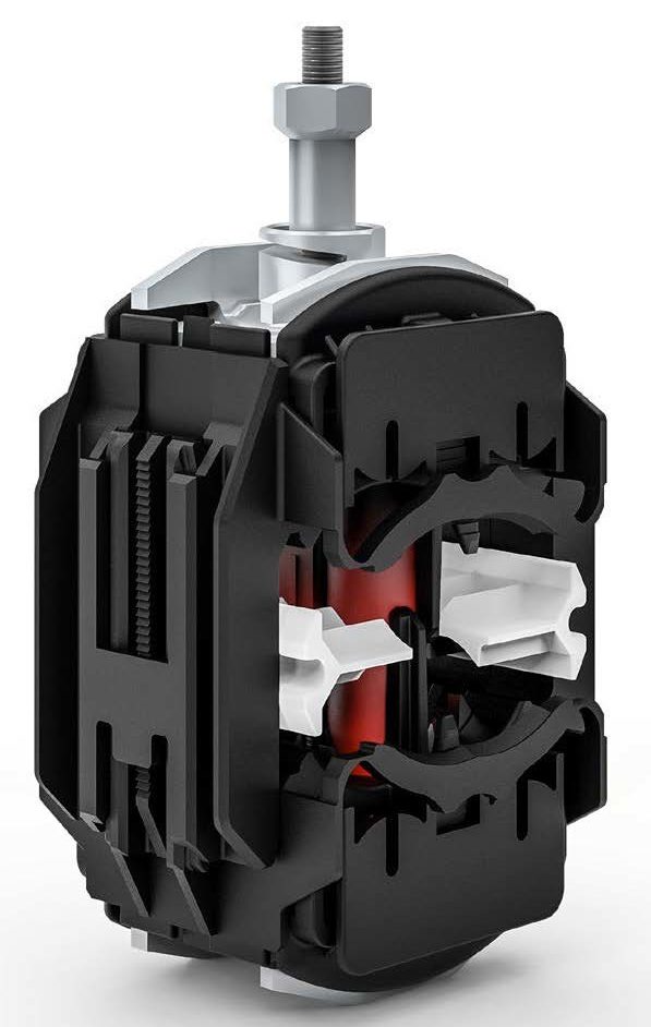
The ISICOMPACT establishes all contacts for a 4-conductor cable branch using a single screw connection. When the screw connection is tightened, contact is established by piercing the insulation on the main line and branch lines.
Once the required clamping force has been achieved, the screw shears off and thereby ensures successful installation. By providing protection against contact and thus against electrical hazards, the ISICOMPACT is designed for live line work.
It is currently the only cable tap connector that also meets the strict requirements of BSI 862 – a German approval that enables a process for live line work without additional PPE and requires LLW electricians to undergo special training and the LV power network provider to be approved.
Six screws become ONE
ISICOMPACT reliably creates a branch connection from the supply cable to the end customer with just one screw. This simplifies and speeds up installation.
Where as conventional “clamping rings” have at least six screws, one or more of which are usually poorly accessible, the single screw on the ISICOMPACT can be placed on the cable to suit conditions, and conveniently tightened from above or from the side.
Simple & safe installation
Tightening the screw establishes all conductor contacts reliably and safely to form the cable branch. Insulation does not have to be removed from the conductor; contacts are established by piercing the insulation.
Spring pressure plates on both sides of the clamp ensure permanent contact force. The design and installation sequence ensure protection against contact with live parts throughout all work steps.
Live line working
Providing shock-proof protection against electrical hazards, ISICOMPACT is designed for live line working. The “green” version ISICOMPACT plus is the only cable tap connector approved by employer’s liability insurance association BG ETEM for live line work without additional PPE. It meets the strict requirements of DGUV Information 203-031 (formerly BGI 862).
ISICOMPACT – Reliable home connection with just one screw
High flexibility
Compared to conventional cable tap connectors, ISICOMPACT offers significantly larger clamping ranges and high flexibility in use. Altogether there are two standard sizes and seven variants. ISICOMPACT multi combines the S, M and 3 1/2 variants in one product.
As a result, electricians are equipped for all eventualities. At the same time, the smaller number of variants reduces the risk of using the wrong type and cuts inventory costs.
Unique shear-off technology
ISICOMPACT features a specially developed shear nut which performs two tasks during fitting. It defines the installation end-point and minimises the clamp’s dimensions. Once the optimal contact force is reached, the shear nut operates and the protruding section of the screw breaks away burr-free. Subsequently, ISICOMPACT fits into all commercially available cast resin joints.
Currently used by all major energy suppliers. ISICOMPACT cable branch technology
Everything from a single source
Clamping ring and cast resin joints from the inventor of multi-conductor cable branch technology. As a contact technology specialist and solution-oriented system provider, PFISTERER offers a wide selection of cast resin joints to complement the ISICOMPACT connection system, as well as complete matching sets comprising a cast resin joint and the cable tap connector. Our proven two-component cast resins with excellent flow characteristics are available in tins or in a practical two-chamber bag.
ISICOMPACT Benefits
No stripping of conductors
Insulation does not have to be removed from the conductor
Shock-proof protection against electrical hazards
One-Screw solution with defined shear torque
Consistent operational reliability, tested to DIN VDE 0220 part 3
Reduced range of variants due to large area of application
Thorne & Derrick stock and distribute PFISTERER CONNEX Connectors for medium / high voltage cable connection and termination to electrical systems up to 33kV – we provide competitive prices for PFISTERER CONNEX connectors used to terminate and connect polymeric insulated MV-HV cables into gas insulated switchgear and electrical equipment from extensive UK stocks.
Thorne & Derrick are national distributors of LV, MV & HV Cable Installation, Jointing, Substation & Electrical Equipment – servicing businesses involved in cabling, jointing, substation, earthing, overhead line and electrical construction at LV, 11kV, 33kV, 66kV and EHV. Supplying a complete range of power cable accessories to support the installation and maintenance of low/medium and high voltage cable systems:
The SEANEX inner cone solution is an offshore variant of the successful Connex HV connection system that is specially adapted for 66kV inter-array cabling.
Special Thanks To Ian Griffiths – Earthing System Design HV
In this Guest Blog from Ian Griffiths (GreyMatters Principal Partner) we learn how what the difference is between grounding, earthing and bonding? That’s a question our readers and clients ask often.
Also, we’re asked quite a bit about earthing and bonding in general. So, there’s an unusually large amount of confusion around the term Earthing and Bonding. Or, for our friends in the states; you might come across the term grounding and bonding.
Therefore, in this piece, I aim to clarify the difference between – what is grounding, Earthing and what is bonding and whether there is a difference.
Breaking things down into simple terms; Earthing – grounding can mean all things to all people. Hence, it is more realistic to think of Earthing as the ‘electrode’ itself. Also, known as the Earth Termination. This reference refers to the physical hardware, such as the copper conductors, rods, etc., that sits buried directly in the geology itself.
Alternatively, Bonding on the other hand usually refers to the above-ground interconnections between the equipment or structures to be bonded.
What’s The Difference Between Earthing & Grounding?
There’s a lot of unnecessary confusion surrounding the difference between the discipline of Earthing and Grounding, which is kind of crazy, because, for the most part, the two are the same.
Earthing is the term used primarily by previous British colonies, whereas, Grounding is used more by those countries where the British had less influence.
So you might see the term Ground Potential Rise (GPR) or Earth Potential Rise (EPR) – both refer to the same thing! It’s purely a localism that has developed over time.
Difference Between Earthing & Bonding – Summary
So, to summarise Earthing and Bonding difference can be categorised as follows:
Earthing is the stuff ‘in’ the ground, and;
Bonding is the stuff ‘above’ ground.
Thus, knowing that some earthing system “stuff” is going to sit above ground level. And some will be below ground is a useful way of thinking about E&B (earthing and bonding). It’s also imperative to understand as part of an E&B design strategy that each item has a subtly different purpose.
One thing is for sure, E&B is a safety-critical aspect on all HV networks, including Rail Network electrification schemes. And as part of GreyMatters mission to help save lives while making life as easy as possible to deal with us, you’d expect us to jump through some crazy-hard hoops in the process, right?
Sentinel
As a result, one such ‘hoop’ Sentinel. I have to confess, and it’s quite a significant commitment to making initially (November 2017)to become the only Earthing Consultancy on the planet to my knowledge to offer full Sentinel sponsor status for Network Rail E&B projects. This status means PTS certified engineers get trackside in the UK easily without any faff or hassle and full RISQS compliance comes built-in to keep the regulators happy on the governance side.
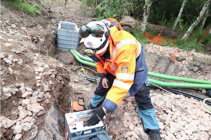
Not only that but we also made some eye-watering (for us) investment in high-energy testing equipment. Furthermore, the readings we take do not suffer from the common, yet not fully recognised rail-related external influences.
Often these sources of error usually cause no-end of uncertainty in a rail environment, i.e. lots of lovely conductive structures that run in parallel for miles. Incidentally, these are quite a headache as a source of interference, when testing using the conventional equipment. Again, this attention to detail is something that makes GreyMatters entirely different. As a result, it’s also something that other sectors can benefit from – not just rail.
Anyway, hopefully, this piece clears up the confusion regarding E&B (Earthing and Bonding) you might have held previously and given a small insight into E&B testing headaches on rail projects too.
ABOUT GREYMATTERS
GreyMatters specialise in High Voltage Earthing System Design for earthing systems 1kV-765kV to meet EN 50522 and and international specifications, including 11kV, 33kV and 66kV power systems.
Protecting critical assets and life from the harmful effects of high voltages and lightning strikes globally since 1995
Focussing on high voltage electrical earthing system design, earthing measurement and surveys, lightning protection design, training and policy formulation
THORNE & DERRICK are national distributors of LV, MV & HV Cable Installation, Jointing, Duct Sealing, Substation & Electrical Equipment – we service UK and global businesses involved in cable installations, cable jointing, substation earthing, overhead line and electrical construction at LV, 11kV, 33kV and EHV.
Since 1985, T&D have established an international reputation based on SERVICE | INTEGRITY | TRUST.
Contact us for 3M Electrical, ABB, Alroc, AN Wallis, CATU Electrical, Cembre, Centriforce, CMP, CSD, Elastimold, Ellis Patents, Emtelle, Euromold, Filoform , Furse, Lucy Electric & Zodion, Nexans, Pfisterer, Polypipe, Prysmian, Roxtec, Sicame, WT Henley.
Celebrating Charlie & Ella’s Level 4 Sales Executive Apprenticeships At Thorne & Derrick International, we are proud to champion talent development and recognise the dedication required to achieve professional growth. We are therefore delighted to congratulate Charlie Baines and...
Thorne & Derrick will be Exhibiting at Solar & Storage Live UK 2026 at the NEC Birmingham from 22nd–24th September, showcasing our support for HV Cable Accessories, Joints, Terminations, Separable Connectors, Cable Tooling and Grid Connection Products used across...