

3M Cable Joints & Terminations
Cold Shrink Technology & Moulded Parts For Electrical Installation | Fast & Easy To Install
May 4th, 2021
3M Cold Shrink
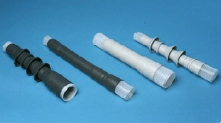
Cold shrink tubing and moulded parts for electrical installation
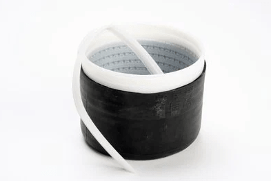
Invented over 40 years ago by 3M, 3M Cold Shrink Technology is designed to make cable insulating, termination and abandonment as simple as possible. The secret of 3M Cold Shrink technology lies inside it, in the form of a plastic coil. After the 3M Cold Shrink Tube has been placed over the joint or cable end, this inner spiral is pulled out. The insulating tube then contracts and seals onto the cable, exerting constant radial pressure for the lifetime of the joint or termination.
3M Cold Shrink Tubes are installed easily and reliably without the use of cable jointing tools (e.g. gas torches or naked flames). The Cold Shrink tubes manufactured by 3M Electrical are made from extruded EPDM (Ethylene-Propylene-Diene-Monomer) or silicone rubber that are stretched onto a spiral core.
The benefits of cold shrink tubes clear a long-term environmental seal that has high performance even in extreme conditions. The tool-free installation reduces downtime, installation time and training requirements.
Cold Shrink Applications
- Electrical insulation up to 1000 volts
- Insulation of low voltage joints for electrical cables
- Cold Shrink is suitable for indoor and outdoor use
- Mechanical protection of installation
- Cable jacket repair
- Protecting and sealing non-electric applications

Silicone
Cold Shrink Advantages
- Easy and safe installation
- High reliability
- High shrink ratio
- Compressive environmental seal
- Tool-less installation of Cold Shrink
- Reduced contractor training requirement
- Reduced installation time compared to heat shrink
- High performing in extreme conditions


THORNE & DERRICK are national distributors of LV, MV & HV Cable Installation, Jointing, Duct Sealing, Substation & Electrical Equipment – we service UK and global businesses involved in cable installations, cable jointing, substation earthing, overhead line and electrical construction at LV, 11kV, 33kV and EHV.
Since 1985, T&D have established an international reputation based on SERVICE | INTEGRITY | TRUST.
Contact us for 3M Electrical, ABB, Alroc, AN Wallis, CATU Electrical, Cembre, Centriforce, CMP, CSD, Elastimold, Ellis Patents, Emtelle, Euromold, Filoform , Furse, Lucy Electric & Zodion, Nexans, Pfisterer, Polypipe, Prysmian, Roxtec, Sicame, WT Henley.

3M™ Scotchcast™ Resin 4 GS with Colour Indicator and 92 GS Series Resin Kits
May 4th, 2021
3M 92 GS Series Kits – Mould Body and Connection
3M™ Scotchcast™ Resin 4 GS with Colour Indicator
Professional Cable Jointing Solutions
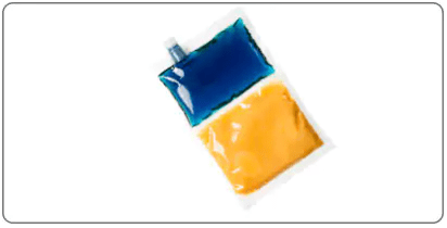
The new 3M™ Scotchcast™ Resin 4 GS is a CMR (Carcinogenic, Mutagenic, Reprotoxic) free electrical cable jointing resin has a unique colour mixing indicator to show installers when the resin is correctly mixed by the cable jointer.
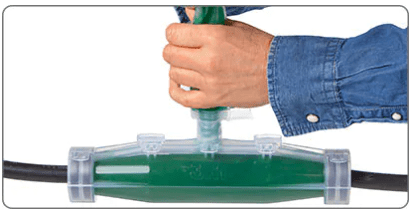
Scotchcast™ Resin 4 GS comes in a 2-part transparent bag with integrated pouring spout, ensuring mess-free effortless application. The high-performing formulation means the resin will cure to joint or repair the cable, even in the presence of water.
These 3M Scotchcast resin kits are tested according to EN 50393, CMR-Free substance, compatible with EU Directive 2002/95 / EC (RoHS) and EU regulation 1907/2007/ EC (REACH).
What is 3M Scotchcast Resin 4 GS?
- A unique electrical jointing resin from 3M
- Newly designed formulation provides colour change indicator for mixing
- Free of CMR substances, Isocyanate, Halogens and SVHC
- Enhanced water and humidity resistance during curing
- Mess free, rapid installation of the cable joints for low voltage cables
- Supplied as bags or as part of the Scotchcast 92 GS Series Resin Kits
Simple, colour indicating mixing
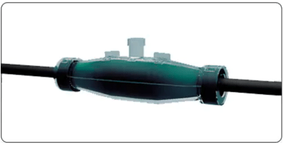
Through a colour change indicator, the 3M Scotchcast resin will turn green when properly mixed by the installer, engineer or cable jointer.
- Newly designed CMR-free formulation
- Unique colour change indicator
- Enhanced water and humidity resistance
- Fully integrated mess-free delivery spout
- Immediate power-up
- Choice of bag sizes to suit your application

*Gel time at 23°C for 92-NBA 3 GS
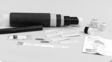
3M Scotchcast 92 GS Series
Resin Kits
3M Scotchcast 92 GS Series Resin Joint Kits with Resin 4 GS are easy to install, mess-free applications with 3M professional cable jointing solutions.
|
 |
|
 |
|
 |
|
 |
|
 |
|
 |
3M – DISTRIBUTORS, STOCKISTS & SUPPLIERS

Thorne & Derrick provide competitive prices and fast delivery from stock for the complete range of 3M Scotchcast and Cold Shrink cable joints, terminations, resins and Scotch electrical tapes – we stock high voltage cable joints and terminations manufactured from 3M using Cold Shrink for 11kV and 33kV cables.
LV, MV & HV Jointing, Earthing, Substation & Electrical Eqpt
Thorne & Derrick International are specialist distributors of LV, MV & HV Cable Installation, Jointing, Duct Sealing, Substation & Electrical Equipment – servicing UK and global businesses involved in cable installations, cable jointing, substation, overhead line and electrical construction at LV, 11kV, 33kV and EHV.
THORNE & DERRICK Product Categories: Duct Seals | Cable Cleats | Cable Glands | Electrical Safety | Arc Flash Protection | Cable Jointing Tools | Cable Pulling | Earthing | Feeder Pillars | Cable Joints LV | Joints & Terminations MV HV
MV & HV Cold Shrink | Cable Accessory Failure Modes
March 8th, 2021
MV & HV Cold Shrink | Cable Accessory Failure Modes
MV & HV cold Shrink
What is Cold Shrink for Medium and High Voltage Cables?
Developed in the 1970’s by 3M, MV & HV Cold Shrink technology has been found to be safer, more reliable and easier to install for the jointing, terminating and abandoning of power cables.
3M Cold Shrink is made from either EPDM (Ethylene-Propylene-Diene-Monomer) or silicone rubber, that is expanded onto a spiral core. After the cold shrink tube has been placed over the joint or cable termination end, this inner spiral is pulled out. The insulating tube then contracts to its pre-stretched size and shrinks onto the cable, exerting constant radial pressure for the lifetime of the joint or termination.
Cold Shrink Offers the Maximum Mechanical Protection
Cold shrink products have a 45+ year track record of performing exceptionally well in indoor and outdoor environments, including under harsh conditions.
The silicone material conforms well to cable bends, which ensures long term reliability against moisture ingress, or voids within the installation. It is shows excellent performance in the following environments:
- Refineries
- Coastal environments
- Altitude
- Dusty environments eg. solar power plants, wind farms
- Vibrations eg. railroad, subway
- Underwater environments
- Overhead joint applications
Cold shrink
Cable Accessory Reliability
There are a variety of issues that can impact on the reliability of MV & HV cable accessories.
These issues include:
- Improper Accessory Selection
- Difficult to Follow Instructions
- Workmanship
- Number of Installation Steps
- How the Accessory is Delivered to the Cable
- Materials Used to Manufacture the Accessory
- Tolerances & Product Design
- Environment Factors
- Training & Support
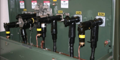
Medium Voltage cable accessories
3M Electrical manufacture a range of cable accessories for medium and high voltage cables, including cold shrink, which enable quick and easy installation and efficient operation.
Terminations |
Separable Connectors |
Joints / Splices |
||
|
|
|
|
||
| 3M™ Cold Shrink QT II and QT III Indoor and Outdoor (skirted) | 200 Amp Load Break Elbows | 3M™ Cold Shrink QS III Cable Splice Kits | ||
| 600 Amp Dead Break T bodies |
3M™ Cold Shrink QS4 Integrated Splice Kits |
|||
|
|
|
Further Reading
- 66kV Terminations | NEW Stock Introduction for 3M Cold Shrink Cable Terminations
- Stress Control | MV Cable Terminations by 3M Electrical
- Cable Jacket Repair | 3M Electrical Webinar
3M – DISTRIBUTORS, STOCKISTS & SUPPLIERS
Thorne & Derrick provide competitive prices and fast delivery from stock for the complete range of 3M Scotchcast and Cold Shrink cable joints, terminations, resins and Scotch electrical tapes – we stock high voltage cable joints and terminations manufactured from 3M using Cold Shrink for 11kV and 33kV cables.
Thorne & Derrick
LV, MV & HV Jointing, Earthing, Substation & Electrical Eqpt
Thorne & Derrick International are specialist distributors of LV, MV & HV Cable Installation, Jointing, Duct Sealing, Substation & Electrical Equipment – servicing UK and global businesses involved in cable installations, cable jointing, substation, overhead line and electrical construction at LV, 11kV, 33kV and EHV.
THORNE & DERRICK Product Categories: Duct Seals | Cable Cleats | Cable Glands | Electrical Safety | Arc Flash Protection | Cable Jointing Tools | Cable Pulling | Earthing | Feeder Pillars | Cable Joints LV | Joints & Terminations MV HV
An Assessment of Five Factors Affecting The Life Expectancy Of A Medium Voltage Electrical Splice
August 11th, 2020
Cable Splice Lifetime Cycles
-
Written by George Fofeldea Power Engineer | 3M Canada August 2019
Abstract
How long can a medium voltage
Cable splice last?
There are many parameters that help to determine the overall life expectancy of a cold shrink or heat shrink cable splice. Of these parameters, there are five key reliability identifiers that give us great insight when estimating the overall life expectancy of an electrical cable splice. Those five identifiers are:
- Technology
- Materials
- Design
- Workmanship
- Testing procedures
Introduction
3M™ Cold Shrink QS-III Splice was designed for easy cable splice installation and high reliability. It was introduced to the North American market in 1996.
The silicone rubber QS-III design revolutionized power cable splicing by addressing the installation pitfalls of traditional splices, which required pushing, pulling or heat.
By eliminating the need to apply heat and force, 3M™ Cold Shrink QS-III Splice offered the market a safer and more reliable solution to splicing medium voltage power cables.
Our over 23 years of field experience with 3M™ Cold Shrink QS-III Splice and over 40 years of field experience with 3M™ Cold Shrink QT-II and 3M™ Cold Shrink QT-III Terminations (Fofeldea G. 2018) helps us formulate a more robust understanding regarding the life expectancy of medium voltage cable accessories.
➡ Did you know? – 3M invented cold shrink technology over 50 years ago!
Materials & Methods

3M Shrink QS-III Splice
Medium voltage electrical splice life expectancy was determined using five critical reliability factors: technology, materials, design, workmanship and testing procedures.
The evaluation: an examination based on 3M™ Cold Shrink QS-III Splice’s 23 years in the field, failure investigation reports, and 50 years of cold shrink materials and design experience.
Discussion
By looking at the five reliability factors that affect the life expectancy of a medium voltage cable splice, this paper aims to identify the product with the highest reliability.
Technology
1.1. Disadvantages of heat shrink splice technology
In general, heat shrink splices require more installation steps compared to cold shrink splices (e.g., applying heat so the splice can conform to the cables) – leaving more room for installation error by the cable jointer.
Uneven heat application can result in burning different heat shrink layers and uneven wall thickness. If such mistakes are made during the installation process, the life expectancy of a heat shrink splice can be reduced.
1.2. Disadvantages of push-on splice technology
Aside from the more cumbersome installation steps (i.e., greasing cables, pushing splice body back and forth, asymmetrical cable preparation cutbacks, etc.), one significant disadvantage of push-on splices is the limited tolerance during installation. The push-on splice design only allows for a minimal semi-con overlap of ½ inch and a freshly installed splice can easily move, reducing this critical overlap.
For optimal life expectancy, a push-on splice must provide enough initial pressure so that it does not electrically fail. Additionally, the initial installation pressure must be low enough to allow for pushing the splice body onto the cable. However, research shows that for push-on splices, up to 90% of the initial pressure is lost during heat cycles (Amyot, N., et al. 2001), which reduces the overall life expectancy of the splice. Comparatively, the initial pressure in 3M™ Cold Shrink QS-III Splice is much higher and thermal cycles do not lower the pressure, which results in improved cable splice reliability.
1.3. Advantages of cold shrink splice technology
None of the disadvantages highlighted above apply to 3M Cold Shrink Technology. 3M designed this technology for long-term reliability – to last the life of the cable while helping to ensure excellent electrical performance. The dynamic “living” seal expands and contracts with variations in temperature and load on the cable.
The 3M™ Cold Shrink QS-III Splice firmly shrinks onto the cable insulation – providing an active seal, without loss of pressure due to cable heat cycling. Additionally, 3M™ Cold Shrink QS-III Splice has a wide application range, and the overall splice body design (i.e., length of semi-conductive inner electrode or outer shell) is designed to help minimize potential installation errors.

3M Cold Shrink QS-III Splice provides constant inward pressure
Materials
When considering cable splice life expectancy, we also must evaluate the various materials used to manufacture cold shrink splices. There are two main types of materials used to manufacture cold shrink splices: ethylene propylene diene monomer (EPDM) rubber and silicone rubber.
The splices made from EPDM rubber have a lower elasticity coefficient, making them more difficult to install in cold weather. As a result, this material sometimes requires heat to shrink onto the cable.
130°C or 140°C
There are two types of silicone rubber materials used to manufacture cold shrink splices:
1. a clear, “unfilled” liquid silicone rubber
2. one that is “filled” with thermally conductive additives
The heat dissipating additives used in the 3M™Cold Shrink QS-III Splice enables us to meet the 130°C or 140°C cable emergency overload temperature requirements of IEEE 404, on both aluminum and copper conductors. (IEEE 404 requires that heat cycling testing be done at cable emergency overload temperature.)
3M™ Cold Shrink QS-III designs are tested to the worst-case scenarios on aluminum (AL) conductors with AL compression connectors, and cross-linked polyethylene (XLPE) insulation. Because of the unique silicone material used for the 3M™ Cold Shrink QS-III Splice the connector area in a 15 kV 3M™ Cold Shrink QS-III Splice typically runs 10°C – 15°C cooler than the conductor itself (see Figure 1 on page 10).
This is important because a good thermal heat dissipation by the splice body helps prolong life expectancy of an installed splice.
Cable Splice Design
Splice body design has an important influence over the long-term reliability of a medium voltage cable splice – directly impacting the life expectancy. Since we learned above that the material used for 3M™ Cold Shrink QS-III Splice helps to prolong life expectancy of an installed splice, we will now evaluate the design of 3M™ Cold Shrink QS-III Splice.
3.1. Electrical stress inside the cable splice
The electrode design of the 3M™ Cold Shrink QS-III Splice is unique. It is designed to help provide precise control and management of the electrical stress along the cable-insulation interface and over the connector shield within the splice insulation. The precision geometry incorporates rounded inner electrode ends with an undercut inner electrode design and rounded outer semi-conductive shell to help reduce electrical stresses.
The 3M™ Cold Shrink QS-III Splice design requirements call for the maximum interfacial stress to be no greater than half of the stress over the connector shield and the maximum stress over the connector shield to be approximately equal to two-thirds of the maximum stress in the cable (see Figure 2).
Due to 3M™ Cold Shrink QS-III Splice’s precise geometry, the electrical stresses within the splice are less than those experienced by the cable insulation. E4 in Figure 2 is the highest electrical stress for a 15 kV cable and is approximately 72 V/mil. The maximum stress in the 3M™ Cold Shrink QS-III Splice Body for a 15 kV cable is E2 and is approximately 36 V/mil – about half of E4. The installer cannot interfere in any way with E2 since it is inside the splice body (in other words, 3M manufacturing controlled). This low E2 stress enhances the safety and reliability of the splice body.
Furthermore, E3 in Figure 2 is situated at the cable insulation-splice body interface. E3 is an extremely important point since any cable preparation inconsistencies (e.g., potential knife cuts, dirt, humidity, etc., on the insulation) will increase the stress in this area.
With 3M™ Cold Shrink QS-III Splice’s unique undercut inner electrode design, E3 is only 12.7 V/mil and allows for enhanced safety and long-term performance.
To help demonstrate the positive impact of this intricate and precise geometric stress control design, we must look at the basic impulse levels (BIL) of the 3M™ Cold Shrink QS-III Splice.
The 3M™ Cold Shrink QS-III Splice is rated one BIL higher than the corresponding splice classification; e.g., 25 kV splices meet the BIL requirements of 35 kV splices. This superior BIL classification is testimony to the low stresses inside the splice bodies, thus enhancing long-term reliability and improving the overall life expectancy. In a correctly installed 3M™ Cold Shrink QS-III Splice, the electrical stress in the splice is less than the stress in the cable.
E1, E2, E3 < E4
A well-designed splice combined with high-quality manufacturing, and a correct installation can remove the traditional splice weak link in a cable and increase life expectancy of the cable splice installation.
There are some cold applied splices, manufactured using EPDM rubber. In some designs, the manufacturing process of the EPDM-cold applied splices requires the grinding out of the inner conductive layer to provide the insulation interface. This provides a sharp point on the end of the electrode and a step between the insulation and the electrode, which is why a large amount of grease is required to lower electrical stress at these points.
In contrast, the 3M™ Cold Shrink QS-III Splice electrode is molded and designed so that the electrode has a round shape, to help minimize the electrical stress. Minimizing electrical stress helps provide better long-term performance.

Furthermore, some EPDM-cold applied splices have a separate cold applied insulation shield as part of the manufacturing process. As a result the complete splice body cannot be tested to the two production test requirements as requested by the IEEE 404 – the standard allows for different material and subcomponent tests in exchange.
3M™ Cold Shrink QS-III Splice is one molded splice body and each body is tested according to the production
test requirements of the IEEE 404, which help enhance safety and reliability.
3.2. Complete continuation of all cable layers
3M™ Cold Shrink QS-III Splice continues all the layers of the cable. The outer shell of the splice consists of a thick 3-4 mm layer of semi-conductive material, with short-term short circuit current initiating capacity. This layer overlaps the cable semi-conductive layer with a firm grip, and forms a solid shield of semi-conductive material, from one side to the other of the splice.
This helps provide long-term reliability insurance, as it does not rely on a copper mesh for semi-conductive layer continuity, as seen with other cold applied designs.
The 3M™ Cold Shrink QS-III Splice bodies comply with the requirements of the IEEE 592 (also known as the “nail test”). This is because of the thick, molded outer semi-conductive shell. Other cold applied designs use a thinner painted outer semi-conductive layer and cannot comply with the IEEE 592 requirements.
While compliance to IEEE 592 is not mandatory as per IEEE 404, 3M™ Cold Shrink QS-III Splice does comply with the IEEE 592 test, offering a superior and more reliable product.
3.3. Margin of error in installation
The length of the 3M™ Cold Shrink QS-III Splice allows the outside semi-conductive layer to extend over the cable semi-conductive layer, past the minimum ½ inch requirement. This makes the splice more forgiving when it comes to mispositioning errors.
Similarly, the inner semi-conductive electrode is quite long, allowing for use of any long or short connectors and minimizes mistakes in insulation length removal. Therefore, the design of 3M™ Cold Shrink QS-III Splice helps decrease the margin of error during installation.
3.4. BIL voltage
As described in Section 3.1, 3M™ Cold Shrink QS-III Splice is tested for a normal AC voltage level (e.g., 15 kV, 25 kV, 28 kV, etc.) and exceeds the BIL requirements of the next AC voltage level. This is due to the low electrical stress design criteria that 3M employs and the many design features that are incorporated in the 3M™ Cold Shrink QS-III Splice body.
Basic Insulations Levels (BIL) reveal the safety and reliability of a given design, which is why successive BIL test rounds are done in the IEEE 404. It should also be noted that 3M conducts other internal tests, exceeding IEEE 404 requirements. For example, a 25 kV AC splice is required to pass a 150 kV BIL.
3.5 Quality and reliability in manufacturing
Each individual 3M splice body is factory tested – two production tests (PD and AC withstand) are performed. A manufacturing date stamp on a 3M™ Cold Shrink QS-III Splice indicates that the splice body has passed both production tests and are defect-free. As a result, it is unlikely for a customer to receive a defective product.
COld Shrink Workmanship
Workmanship is a key component in every power cable accessory installation. Although 3M™ Cold Shrink QS-III Splice is designed to help mitigate many installation errors through design, proper cable preparation techniques must be employed.
The same cable preparation techniques are to be used regardless if the cable will be spliced or terminated on a pole or terminated through an elbow or deadbreak connectors. 3M application engineers conduct failure investigations and provide end users with analysis reports that identify root causes for failures and make suggestions for improving installations.
The majority of these laboratory investigations pinpoint poor workmanship in cable preparation techniques as the leading root cause for the failures, in conjunction with/or separate from other types of mistakes (e.g., mispositioning of the splice body, wrong cutbacks, connector related installation mistakes, incorrect use of certain tapes, etc.).
➡ Did you know? – 3M offers online training modules to help our customers improve their cable preparation skills and medium voltage splice installation techniques.
Cable Splice Testing procedures
Many different cable testing procedures are available and used in the field. The IEEE 400 describes the test methods and procedures. Not all test methods are equal in the sense that the cables are stressed differently. The IEEE 400 also lists the advantages and disadvantages of the given test methods.
For example, over the years many utilities have moved away from Direct Current High Potential (DC Hi-Pot) testing due to the many drawbacks that this type of testing presents and since it ages and speeds time to failure of an existing cable with incipient defects before testing. Type testing done in 3M laboratories both on new and aged splices removed from the field help us understand long-term performance and help better predict life expectancy.
Field cable testing depending on the exact test method employed can negatively impact the remaining cable life and the estimated life of the splices in that loop. The testing conditions, the test method, the number of tests done over the life of the cable with splices included in the circuits, are all factors that must be considered when estimating life expectancy of cables and splices. Many of these factors are within the unique control of the utility.
Conclusion
The life expectancy of the 3M™ Cold Shrink QS-III Splice helps meet or exceed the life expectancy of the cable because 3M employs the best materials, design and manufacturing techniques available, to make the most reliable cable splice possible.
Over 23 years of excellent 3M™ Cold Shrink QS-III Splice track record in conjunction with over 50 years of cold shrink technology innovation have led to the development of cold shrink splice and termination products for applications up to 69/72.5 kV (3M Company. 2012) that have helped enhance the safety, reliability and life expectancy of cable accessories.

Figure 1: Temperature profile for a 15kV cable splice configuration

Figure 2 15kV Stress Plot
References
- 3M Company. 2012. 3M™ Cold Shrink Joints and Terminations for high voltage applications
- Amyot, N., et al. 2001. The Effect of Thermal Cycling on the Cable Joint Interfacial Pressure
- Fofeldea, G. 2018. Geometric vs. Capacitive Stress Control: choosing cable termination accessories to help reduce
electrical stress - Fofeldea, G. 2015. How do you take your splice? Integrated or not

THORNE & DERRICK are national distributors of LV, MV & HV Cable Installation, Jointing, Duct Sealing, Substation & Electrical Equipment – we service UK and global businesses involved in cable installations, cable jointing, substation earthing, overhead line and electrical construction at LV, 11kV, 33kV and EHV.
Since 1985, T&D have established an international reputation based on SERVICE | INTEGRITY | TRUST.
Contact us for 3M Electrical, ABB, Alroc, AN Wallis, CATU Electrical, Cembre, Centriforce, CMP, CSD, Elastimold, Ellis Patents, Emtelle, Euromold, Filoform , Furse, Lucy Electric & Zodion, Nexans, Pfisterer, Polypipe, Prysmian, Roxtec, Sicame, WT Henley.

How To Protect LV MV Cables From Electrical Arc Faults & Fire
June 2nd, 2020
3M Scotch 77 Arc Faults & Fire Proofing Tapes
Electrical Arc Faults
Electrical arc fault generated fires can be of up to 2000 Degrees Fahrenheit.
That’s more than twice as hot as the temperature of the surface of Venus and enough heat to melt gold.
Furthermore, this is more than enough to destroy expensive electrical cables.
The resulting catastrophes of an electrical arc fault generated fire means that we have to find a solution to protect cables against these dangerous and damaging fires.
In this Article we show how 3M Scotch® Fire Retardant Electric Arc Proofing Tape 77, can protect low (LV) and medium voltage (MV) electrical cables from electrical arc faults and their resulting fires.

Arc Faults Can Be Catastrophic
Protecting cables From ARC Faults
with 3m scotch 77 tape
 Even after a short exposure to a flame, an unprotected cable will catch fire, and continue to burn. Increasing the likely-hood of causing other fires and causing additional major damage. One fire could wreak absolute havoc on cables, or the equipment they are connecting.
Unless of course you can help prevent them from catching fire in the first place. Scotch fire retardant electric arc proofing tape, is designed to protect Low Voltage and Medium Voltage cables and cable accessories from arc faults and the resulting fires.
3M Scotch 77 tape can withstand a 2000 degree torch blast from 3 inches away, for 3 minutes.
That’s 3 minutes longer than an unprotected cable.
3M Scotch 77 Tapes are 0.76mm thick, arc and fireproofing electrical tapes designed to protect all types of electrical cables. This insulating firewall acts as a heat shield and flame barrier, thus protecting the cables joints and accessories.
Scotch 77 tape is burn resistant.
It will also help prevent cable jacket material from melting and dripping flames onto whatever lies beneath it. When the flame is taken away from a cable protected by 77 tape, that’s it, it doesn’t continue burning. It doesn’t cause additional fires and when the tape is removed, the cable underneath does not show any significant damage, and should not need to be replaced.
That kind of trusted protection is why electrical professionals around the globe have taken notice. Used properly, Scotch brand fire retardant electric arc proofing tape 77, can be the difference between a small problem, and an expensive catastrophe.

Stockists & Suppliers of 3M Scotch Electrical Tapes
SCOTCH 77 Tape
- Manufacturer: 3M Electrical
- Brand: Scotch Tapes
- Stock Code: 3M Scotch 77 Tape
- Product Category: Electrical Tapes
- Sub Product Category: Corrosion & Fire Protection Tapes
- 3M Scotch 77 Tape Application: Protects cable from arc and fire until limiting devices can interrupt faulted circuit. Use on high-energy cables that are within 18″ of other high energy cables. Available in black and white the white version is easily visible and easy to inspect
- 3M Scotch 77 Roll Sizes:
- 1-1/2″ x 20′ (38 mm x 6,1 m)
3″ x 20′ (76 mm x 6,1 m)
➡ Also available from Thorne & Derrick are Cold Shrink and Scotchcast – contact us for prices and delivery for the 3M Scotchcast range of cable joints and resins.

Self Amalgamating Tapes | Mastic Tapes | Corrosion & Fire Protection Tapes
Thorne & Derrick

LV, MV & HV Jointing, Earthing, Substation & Electrical Eqpt
Thorne & Derrick International are specialist distributors of LV, MV & HV Cable Installation, Jointing, Duct Sealing, Substation & Electrical Equipment – servicing UK and global businesses involved in cable installations, cable jointing, substation, overhead line and electrical construction at LV, 11kV, 33kV and EHV.
THORNE & DERRICK Product Categories: Duct Seals | Cable Cleats | Cable Glands | Electrical Safety | Arc Flash Protection | Cable Jointing Tools | Cable Pulling | Earthing | Feeder Pillars | Cable Joints LV | Joints & Terminations MV HV
