

Blog
Cable Pulling Considerations
June 11th, 2021
Cable basement KW Schattenhalb, Switzerland (c) 2014 Damian Aegerter
-
Special thanks to Damian Aegerter at Braavos GmbH / cableizer.com
for the kind permission to republish
Cable Pulling
In this 3rd article about cable pulling we discuss the usage of the weight correction and sidewall bearing pressure factors plus the conduit jamming ratio.
Transportation, handling, and installation of cables causes often more mechanical stress than what is actually experienced during operation. Therefore, it is important to carefully plan the cable installation, which can be done in Cableizers updated cable pulling module.
General considerations
For Cable Pulling
The conductors of the cable are generally the only members that can bear the pulling forces without damage. Do not use metallic shielding wires, tapes, braids or armor not designed for the purpose in pulling tension calculations.
Pulling different conductor sizes at the same time is not recommended if the conductor size or other cable characteristics are significantly different. If you must pull different size conductors, it must be done with care.
Pulling additional cables into an existing conduit system is generally not recommended. If this must be done, extreme caution must be taken. Of special concern is the cutting action of the tensioned pulling rope.
Some factors and ratios
Usage of weight correction factor
When multiple cables are pulled together, their mechanical configuration in the conduit is changing along the route which exposes them to uneven forces, an imbalance that is causing additional frictional drag. The weight correction factor f_wc is taking this into account by increasing the weight of cable assemblies consisting of more than one single cable.
Formulas for weight correction factors are mostly limited for pulling of up to 3 cables. Some formulas exist for pulling cable assemblies of 4 cables, but they were not leading to consistent results. Cableizer has extended the formulas for cable assemblies of up to 6 cables.
The following examples are calculated with a cable with an outer diameter D_e of 37 mm and a conduit with an inner diameter D_id of 150 mm. In addition, all calculations are also done on the example of a very large conduit (Di_d = 10 m) for validation reasons.
In this case, the cables lie next to each other and do not rub against each other, and the weight correction factor should be negligible (i.e. equal to 1.0).
As can bee seen in the following table, this is the case except for 5/6 cables which have a constant weight correction factor independent of the cable and conduit dimensions. As a consequence, the pulling force calculation in Cableizer for large conduits is rather conservative (i.e. on the safe side).
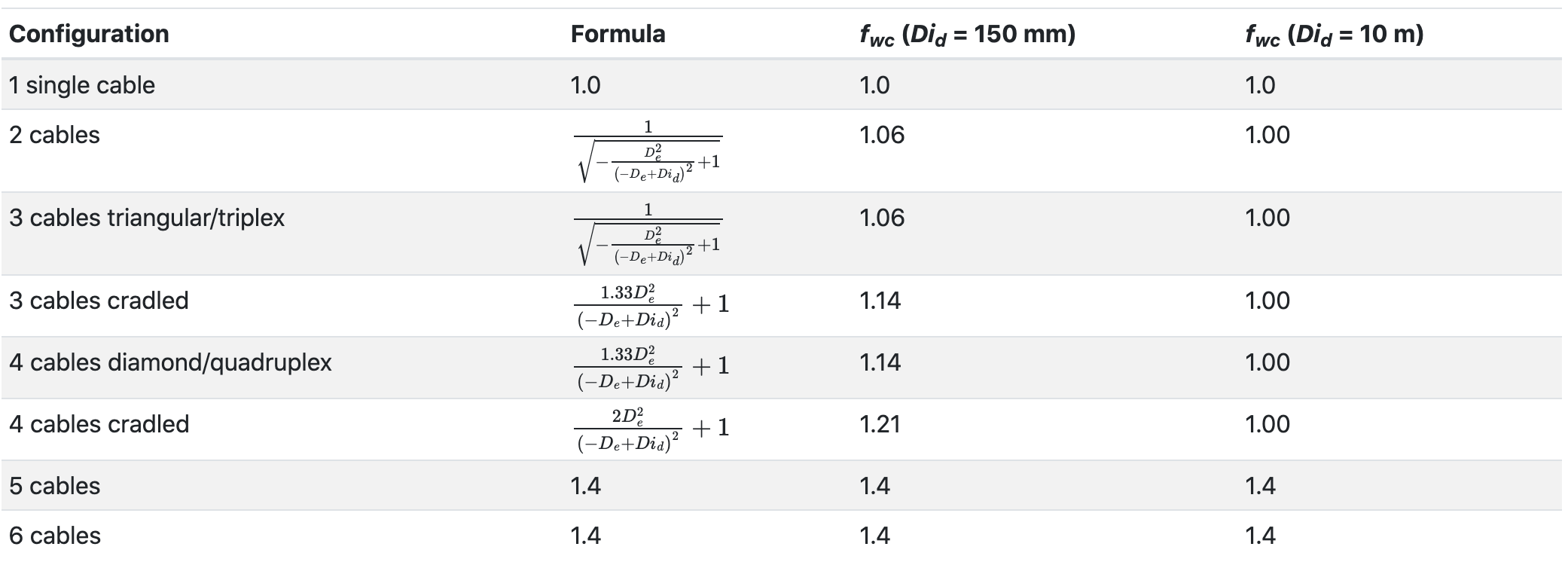
The above figures show that the weight correction factor is as expected incrasing with an incrasing number of cables pulled together.
Cradled configurations do have higher weight correction factors than when the cables are more organized (3 cables triangular/triplex or 4 cables diamond/quadruplex). If you are close to or exceeding the pulling force limits, it can therefore be of interest to investigate if binding the cables together can be an option.
Usage of sidewall bearing pressure factor
Generally, manufacturers do also consider the influence of the weight correction factor when calculating the sidewall bearing pressure.
In Cableizer, this is considered with the sidewall bearing pressure factor f_rad, which can be optionally selected. Its calculations is always dependent on the weight correction factor, but it can be applied to the calculations independently of the weight correction factor. A normal use case is to either apply both f_wc and f_rad or none of them.
The following examples are calculated with a cable with an outer diameter of 37 mm and a conduit with an inner diameter of 150 mm.
The sidewall bearing pressure F_rad is proportional to the sidewall bearing pressure factor and the pulling force. The pulling force F_pull itself is proportional to the weight correction factor and the gravitational force. The gravitational force F_g itself is proportional to the number of cables N_c being pulled together.
As a consequence, the factor f_rad⋅f_wc⋅N_c indicates to what extent the sidewall bearing pressure is increased as compared to the case where a single cable is being pulled.
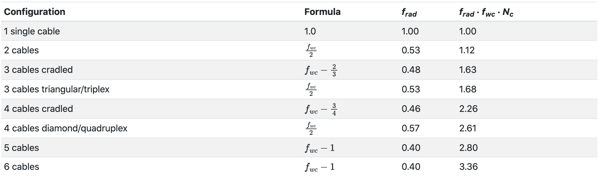
The above figures show that the sidewall bearing pressure on the most exposed cable is increasing steadily with an increasing number of cables being pulled. As expected, cradled configurations do have lower sidewall bearing pressures than when the cables are more organized (3 cables triangular/triplex or 4 cables diamond/quadruplex).
Conduit jamming ratio
Jamming is the wedging of three unbound cables when pulled into a conduit. This usually occurs because of crossovers when the cables twist or are pulled around bends. The conduit jamming ratio is the ratio of the conduit inner diameter Di_d and the cable outside diameter D_e. When calculating jamming probabilities, a 5% factor is used to account for the oval cross-section of conduit bends. The cable diameters should be measured, since actual diameters may vary from the published nominal values.
Cableizer indicates the risk for jamming according to the following table. As shown, different references use different ranges for quantifying the jamming risk. Cableizer does only indicate the jamming ratio for Three cables unbound because even while jamming can occur when pulling four or more cables into a conduit, the probability is very low.
Disclaimer
Always follow the instructions from the cable manufacturer when preparing your cable pull. While some manufacturers disregard the use of the weight correction factor (example I from Brugg Cables), others include it in their calculations (example II from Southwire). In Cableizer, both options can conveniently be calculated.
Cableizer specifically disclaims any warranties, including, but not limited to, the implied warranties of merchantability, accuracy, or fitness for any particular purpose of its calculation results.
The original article can be found on LinkedIn here
Cableizer – The Online Cable Optimizer
Model power cables and calculate current rating, magnetic fields, electrical parameters, short-circuit currents, pulling forces… Experience the full potential of our browser-based simulation platform cableizer.com! Our 14-day free trial includes full access to all the simulation features of Cableizer.
View the other blogs in the Cable Pulling Blog Series below:
- Cable Pulling Calculation Example From Brugg Cables
- Cable Pulling Calculation Example From Southwire
Cable Pulling & Laying Equipment
Suppliers & Distributors
Thorne & Derrick distribute the most extensive range of Low & High Voltage Cable Installation & Electrical Distribution Equipment to the Power Transmission & Distribution industry in the onshore and offshore wind, solar, rail, oil/gas, data centre, battery storage and utility sectors – this includes the most extensive range of Cable Pulling & Cable Laying Equipment to enable the installation of low, medium and high voltage power cables into underground trench or duct.
We service UK and international clients working on underground cables, overhead lines, substations and electrical construction at LV, 11kV/33kV and up to EHV transmission and distribution voltages.
Key Products: MV-HV Cable Joints & Terminations, Cable Cleats, Duct Seals, Cable Transits, Underground Cable Protection, Copper Earth Tapes, Cable Jointing Tools, Feeder Pillars, Cable Ducting, Earthing & Lightning Protection, Electrical Safety, Cable Glands, Arc Flash Protection & Fusegear.
Distributors for: 3M Electrical, ABB, Alroc, Band-It, Cembre, Centriforce, CMP, Elastimold, Ellis Patents, Emtelle, Furse, Lucy Zodion, Nexans Euromold, Pfisterer, Polypipe, ProGARM, Prysmian, and Roxtec.
- Scope –single-source supply of extensive range of products
- Stock – a multi-million pound stock holding provides complete global supply solutions
- Staff – technical support from a trained, proactive and friendly team
- Delivery – UK stock turnaround with express logistics to all international destinations
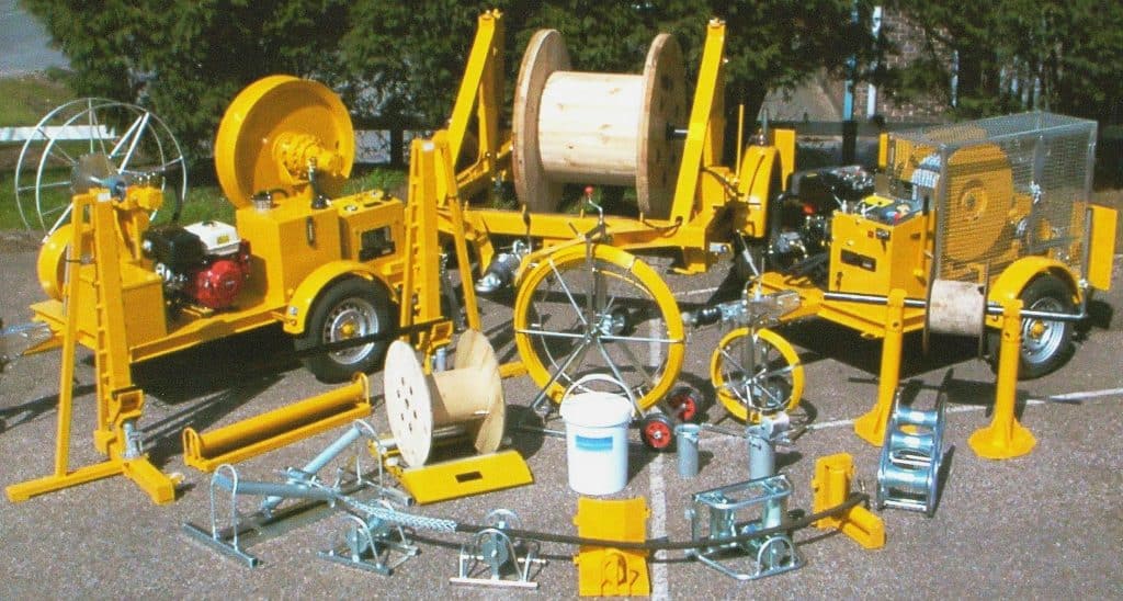

Thorne & Derrick International, based in the UK, are delighted to announce they have entered into an Approved Stockist Agreement with SEB International, the market-leading Cable Laying Equipment manufacturer.
Cable Pulling Calculation Example From Southwire
June 11th, 2021
Cable Pulling Example from Southwire Manual in Cableizer
-
Special thanks to Damian Aegerter at Braavos GmbH / cableizer.com
for the kind permission to republish
Cable Pulling
The 2nd of this blog series features the following cable pulling example from Southwire is an extract from their public document titled ‘Power Cable Installation Guide’, published in 2005. The cable pulling calculation example is found on pages 23ff in the section ‘Typical calculation for cables in conduit‘.
This example validates our cable pulling module and has been added to our test cases, ensuring that the cable pulling calculation won’t unexpectedly and unnoticeably change.
Cable selection
In the Cable tab of the cable pulling module the cable is selected, which in the example is a THHN single-conductor 4/0 AWG copper cable. In the Cableizer cable editor, standard conductor cross-sections A_c can be selected either in mm2 or in AWG/kcmil. Typical values of conductor diameters d_c for this cross section can conveniently be selected for AWG sizes up to 2000 kcmil from UL 1581 and beyond from ASTM B8-11 standards.
In Cableizer, all inputs/outputs are currently only supported in metric units so we converted them for this example. The following table shows the corresponding inputs regarding the cable selection for the Southwire example with cable weight m_tot and external diameter of cable D_e, which covers the case where three identical unbound cables are pulled together. Permissible pull force F_ppc and maximum sidewall pressure F_rad have been manually set to the same values as in the Southwire installation guide.

Conduit selection
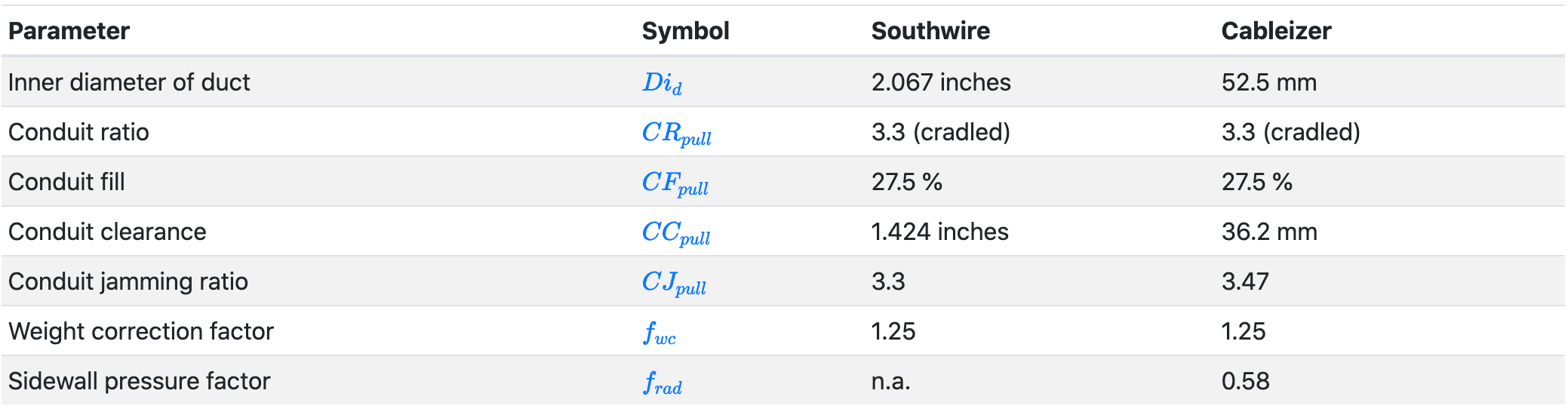
In the Conduit tab of the cable pulling module the conduit (EMT trade size 2 inch) is defined. The parameters include the inner diameter of duct Di_d, the conduit ratio CR, the conduit fill CF in percent, the conduit clearance CC in percent and the conduit jamming ratio CJ.
Cableizer does then verify if the installation is feasible and calculates the weight correction factor f_wc and the sidewall pressure factor f_rad as shown in the following table:
Route editor
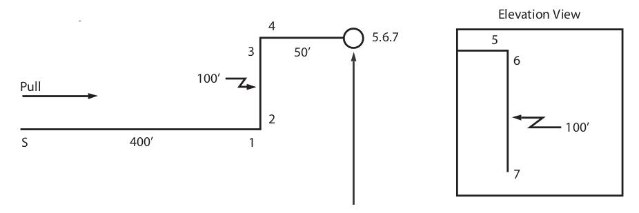
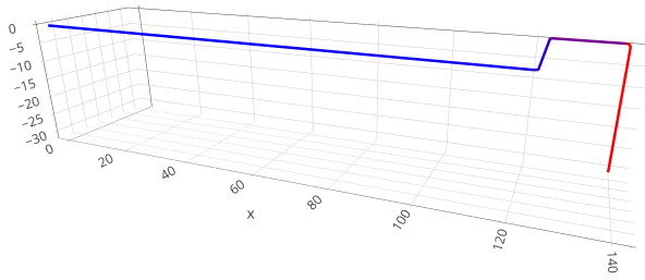
In the Routing tab of the cable pulling module the example route is composed of sections and bends. Bends have an angle ϕ_arc of 90° and a radius r_arc of 914.4 mm (36-inch sweep elbows with an inside radius of 2.91 feet). The friction coefficient μ_dyn is 0.4 all along the route. The following images show the Southwire conduit layout and the Cableizer cable route (in 3D):
Results
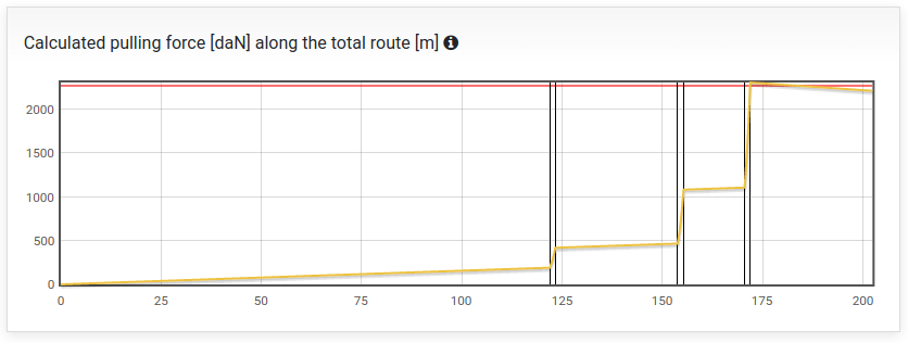
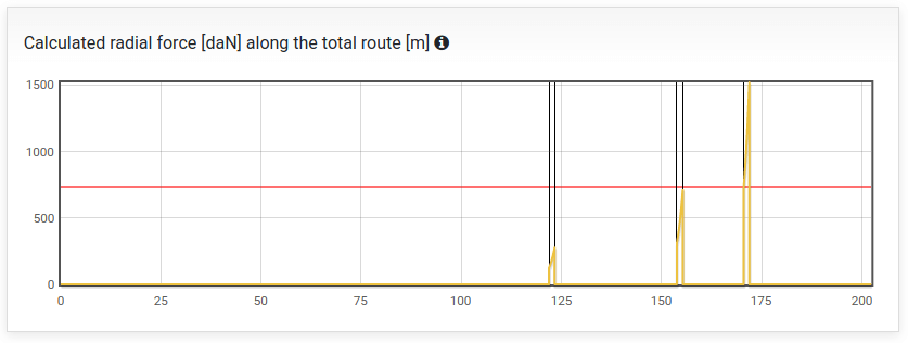
The results show a good agreement with the Southwire installation guide figures, both regarding the pulling force F_pull and the sidewall bearing pressure F_rad. In bend 3, both forces exceed the respective limits:
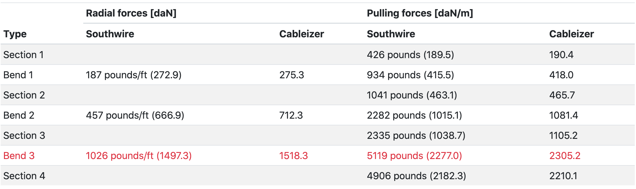
Part of the small differences in the above table can be explained by the fact that Southwire is using approximate equations for both horizontal bends and the vertical concave downwards bend (bend 3). The following figure shows the pulling forces along the cable route for the forward pulling direction. The red line shows the applicable force limits.
A figure showing the radial forces along the cable route is likewise generated.
Backwards pulling direction
In Cableizer, you can also simulate a pull in backward direction. In this case the maximum pulling force is reduced to 1443.7 daN and does not exceed the force limit anymore. The radial force is also considerably reduced to a maximum value of 825.5 daN/m, which is only slightly above the limit.
The forces are reduced despite the fact that the cable has to be pulled up the vertical shaft at the start of the cable route! But having the bends close to the start of the route instead of close to the end of the route significantly reduces the overall pulling forces.
The original article can be found on LinkedIn here
Cableizer – The Online Cable Optimizer
Model power cables and calculate current rating, magnetic fields, electrical parameters, short-circuit currents, pulling forces… Experience the full potential of our browser-based simulation platform cableizer.com! Our 14-day free trial includes full access to all the simulation features of Cableizer.
View the other blogs in the Cable Pulling Blog Series below:
Cable Pulling & Laying Equipment
Suppliers & Distributors
Thorne & Derrick distribute the most extensive range of Low & High Voltage Cable Installation & Electrical Distribution Equipment to the Power Transmission & Distribution industry in the onshore and offshore wind, solar, rail, oil/gas, data centre, battery storage and utility sectors – this includes the most extensive range of Cable Pulling & Cable Laying Equipment to enable the installation of low, medium and high voltage power cables into underground trench or duct.
We service UK and international clients working on underground cables, overhead lines, substations and electrical construction at LV, 11kV/33kV and up to EHV transmission and distribution voltages.
Key Products: MV-HV Cable Joints & Terminations, Cable Cleats, Duct Seals, Cable Transits, Underground Cable Protection, Copper Earth Tapes, Cable Jointing Tools, Feeder Pillars, Cable Ducting, Earthing & Lightning Protection, Electrical Safety, Cable Glands, Arc Flash Protection & Fusegear.
Distributors for: 3M Electrical, ABB, Alroc, Band-It, Cembre, Centriforce, CMP, Elastimold, Ellis Patents, Emtelle, Furse, Lucy Zodion, Nexans Euromold, Pfisterer, Polypipe, ProGARM, Prysmian, and Roxtec.
- Scope –single-source supply of extensive range of products
- Stock – a multi-million pound stock holding provides complete global supply solutions
- Staff – technical support from a trained, proactive and friendly team
- Delivery – UK stock turnaround with express logistics to all international destinations
Thorne & Derrick International, based in the UK, are delighted to announce they have entered into an Approved Stockist Agreement with SEB International, the market-leading Cable Laying Equipment manufacturer.
Cable Pulling Calculation Example From Brugg Cables
June 11th, 2021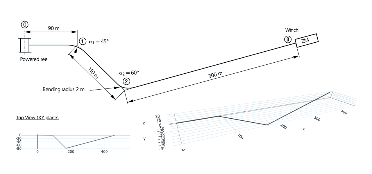
-
Special thanks to Damian Aegerter at Braavos GmbH / cableizer.com
for the kind permission to republish this article
Cable Pulling
In Part 1 of this Blog series we look at how Cableizer cable pulling calculation module has been much improved – today, we present you the application of the module in conjunction with Brugg Cables installation manual.
The following Cable Pulling Calculation example from Brugg Cables is an extract from their public document titled ‘Manual for Transportation and Cable Laying Maintenance’, published 2016. The calculation example is found on pages 12ff.
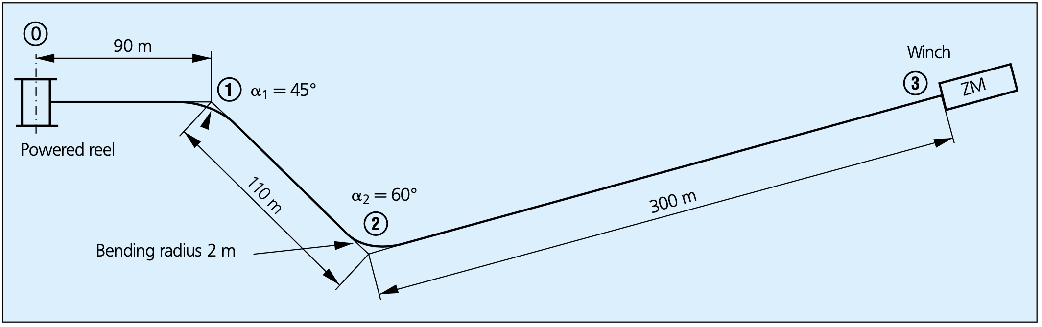
This example validates our cable pulling module and has been added to our test cases, ensuring that cable pulling calculations won’t unexpectedly and unnoticeably change.
Cable selection
In the Cable Tab of the cable pulling module the cable is selected, which in the example is of type XKDT 1×240/35 mm2, 20/12kV. Cableizer does display all relevant cable properties, which closely correspond to the values in the Brugg Cables manual (Cable weight m_tot per m of 3.36 kg, cable diameter D_e of 41 mm, minimum bending radius r_mbp of 615 mm, permissible pull force F_ppc of 9600 N).
Please be aware that Cableizer outputs all forces in [daN] (10 N = 1 daN). In addition it is shown if the cable is a single-core or a multi-core cable, and whether or not it is armoured (for armoured cables, it is possible to select pull on the armour in the cable editor as an alternative to pull on the conductor).

Once the cable has been selected, it is time to select the number of cables that are pulled in together, which in this case is 3. Brugg Cables does not mention whether or not the cables are bound together (Triplex), but from their admissible pull force which is 28800 N and thus thrice the permissible pull force of a single cable, it is concluded that the cables are assumed to be bound together.
For three unbound cables the total permissible pull force is normally assumed to be only twice the permissible pull force of a single cable, as the two cables on the bottom will take all the force (the cable laying on top is not exposed to any friction). If the automatically calculated limit is not suitable, it can be manually entered (e.g. if the pull is made with woven mesh pulling grips).
The admissible sidewall pressure has been selected as 10’000 N/m in accordance with the Brugg Cables manual. Both the permissible pull force and sidewall pressure limit values are optional. However, they should not be omitted as the program will clearly indicate if those limits are exceeded along your cable route.

Conduit selection
In the Conduit Tab of the cable pulling module a PE conduit with an inner diameter of 120 mm is selected in accordance with the Brugg Cables manual.

The conduit ratio CR_pull, the conduit fill CF_pull, and the conduit clearance CC_pull all show that the conduit dimensions are suitable for the intended cable pull. The conduit jamming ratio CJ_pull is not displayed since the three cables are bound together (triplex) and there is no risk for jamming.
💡 Conduit Ratio: this is the ratio between the diameter of a single cable to the inner diameter of the duct. The conduit ratio is a measure for the cable configuration in the duct and Cableizer uses the following ratio limits:
Three cables unbound have a triangular configuration for CRpull < 2.5 and a cradled configuration for CRpull ≥ 2.5.
Three cables triplex always have a triangular configuration.
Four cables unbound have a diamond configuration for CRpull < 3.0 and a cradled configuration for CRpull ≥ 3.0.
Three cables quadruplex always have a diamond configuration.
Please notice that the conduit preview is up to scale and helps to avoid possible input errors.

Brugg Cables calculates without weight correction factor f_wc and sidewall pressure factor f_rad, and so they have not been applied to our calculation. Please consult with your supplier whether or not to apply these factors to your calculations.
Route editor
In the Routing Tab of the cable pulling module the example route is composed of sections and bends.
Please notice that the length of the cable route is slightly different between Cableizer and the Brugg Cables example due to the way the bends are handled. We have also focused on the alternative with an elevation of 20 m within the last section.
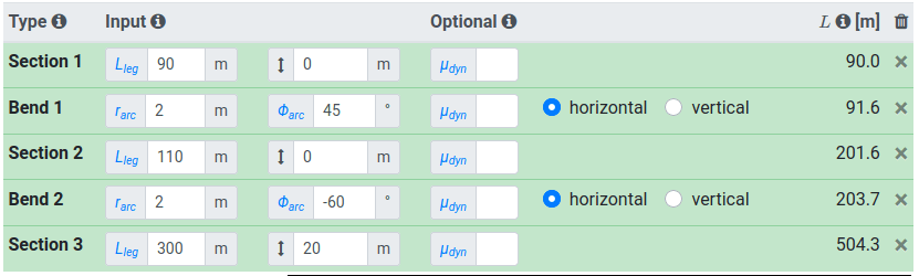
Our two- and three-dimensional preview help you to verify that the input is correct.

The friction coefficient μ_dyn is 0.15 all along the route (Cableizer does allow optional individual inputs for every section or bend). And since the reel is powered, there is no cable reel force.

💡 Dynamic Friction Coefficient: the coefficient of dynamic friction is a measure of the friction between a moving cable and the conduit. The coefficient of friction can have a large impact on the pulling force calculation. It can vary from 0.1 to 1.0 with lubrication and can exceed 1.0 for unlubricated pulls. Pulls should never be stopped and restarted because the coefficient of static friction will always be higher than the coefficient of dynamic friction. The coefficient of friction between a cable exterior (jacket/sheath) and conduit varies with the type of jacket or sheath, type and condition of conduit, type and amount of pulling lubricant used, cable temperature, and ambient temperature. High ambient temperatures can increase the coefficient of dynamic friction for cable having a non-metallic jacket.
Pulling lubricants must be compatible with cable components and be applied while the cable is being pulled. Pre-lubrication of the conduit is recommended by some lubricant manufacturers.
The coefficient of friction between a cable exterior (jacket/sheath) and conduit varies with the type of jacket or sheath, type and condition of conduit, type and amount of pulling lubricant used, cable temperature, and ambient temperature. High ambient temperatures can increase the coefficient of dynamic friction for cable having a nonmetallic jacket.
Pulling lubricants must be compatible with cable components and be applied while the cable is being pulled. Pre-lubrication of the conduit is recommended by some lubricant manufacturers.
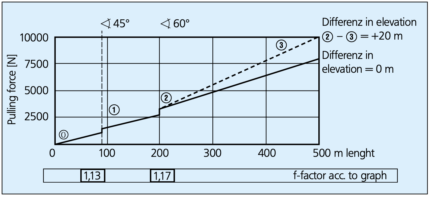
The approximate results show a good agreement with the Brugg Cables manual, which states a maximum pulling force F_pull of 10’215 N and a maximum sidewall pressure F_rad of 1’858 N/m.
The difference in the sidewall bearing pressure is due to the fact that Cableizer is calculating with the inside bending radius of the conduit, while Brugg Cables is considering the radius of the centerline of the bend r_arc (which is also used as input in Cableizer).
The results also show that it is beneficial to opt for a pull in the forward directions if possible, which has both lower pulling forces and sidewall bearing pressures than a pull in the backward direction.
➡ Cable Pulling Force & Tension: calculations of pulling forces or pulling tensions for cable trays are similar to those for pulling cable in conduit, adjusting the coefficient of friction to reflect using rollers and sheaves.
If the sheaves in the bends in cable trays are well-maintained, they will not have the multiplying effect on the force that bends in conduit have. The sheaves will turn with the cable, allowing the coefficient of friction to be assumed zero. This results in the commonly-used approximation for conduit bend equation becoming one. Even though cable tray bends produce no multiplying effect, it is essential for heavier cables to include the force required to bend the cable around the sheave. If the sheaves are not well-maintained, the bend will have a multiplying effect. The pulling force must then be calculated using the same equations used for installations in conduit.
Pulling lubricants must be compatible with cable components and be applied while the cable is being pulled. Pre-lubrication of the conduit is recommended by some lubricant manufacturers. The approximate results display only the pulling forces at the end of the respective sections, while the forward and backward direction tabs display the pulling forces all along the route. The approximate results also use a simplified equation for bends, which does not consider the gravitational forces or the vertical elevations.
Forward direction pulling forces
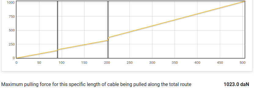
In the Forward Direction and Backward Direction tabs of the cable pulling module, the pull force curves and radial force curves can be calculate and displayed. As shown below, the forward pull force curve does correspond to the curve from the Brugg Cables manual.
Special feature
Pull a cable over a longer route
It is now possible to set a cable length that is shorter than the cable route and get corresponding pull force and sidewall bearing pressure curves.
The software calculates sequentially the pull force and sidewall bearing pressure of the cable being pulled over the whole route in steps of 10 cm. This leads to rising and falling values as the cable enters and leaves bends, slopes and cable pushers. The output provides the highest pulling force and sidewall pressure the cable experiences during the pull.
This feature has been added on customer request. Please let us know if you have any proposals for improvements or clarifications.
The original article can be found on LinkedIn here
Cableizer – The Online Cable Optimizer
Model power cables and calculate current rating, magnetic fields, electrical parameters, short-circuit currents, pulling forces… Experience the full potential of our browser-based simulation platform cableizer.com! Our 14-day free trial includes full access to all the simulation features of Cableizer.
View the other blogs in the Cable Pulling Blog Series below:
Cable Pulling & Laying Equipment
Suppliers & Distributors
Thorne & Derrick distribute the most extensive range of Low & High Voltage Cable Installation & Electrical Distribution Equipment to the Power Transmission & Distribution industry in the onshore and offshore wind, solar, rail, oil/gas, data centre, battery storage and utility sectors – this includes the most extensive range of Cable Pulling & Cable Laying Equipment to enable the installation of low, medium and high voltage power cables into underground trench or duct.
We service UK and international clients working on underground cables, overhead lines, substations and electrical construction at LV, 11kV/33kV and up to EHV transmission and distribution voltages.
Key Products: MV-HV Cable Joints & Terminations, Cable Cleats, Duct Seals, Cable Transits, Underground Cable Protection, Copper Earth Tapes, Cable Jointing Tools, Feeder Pillars, Cable Ducting, Earthing & Lightning Protection, Electrical Safety, Cable Glands, Arc Flash Protection & Fusegear.
Distributors for: 3M Electrical, ABB, Alroc, Band-It, Cembre, Centriforce, CMP, Elastimold, Ellis Patents, Emtelle, Furse, Lucy Zodion, Nexans Euromold, Pfisterer, Polypipe, ProGARM, Prysmian, and Roxtec.
- Scope –single-source supply of extensive range of products
- Stock – a multi-million pound stock holding provides complete global supply solutions
- Staff – technical support from a trained, proactive and friendly team
- Delivery – UK stock turnaround with express logistics to all international destinations
Further Reading | Handling Cable Drums & Laying Cables | A Guide from Nexans

Press Release | Thorne & Derrick Appointed Approved Stockist for UK Leading Cable Pulling Equipment Manufacturer
Feeder Pillars | A Survey of External Enclosure Performance By Ritherdon
June 10th, 2021
Feeder Pillars
Feeder Pillars
Water ingress, Corrosion & Paint Finish of Cabinets and Feeder Pillars
There are many thousands of Ritherdon cabinets and feeder pillars in service and, stainless steel being highly corrosion-resistant, that number is constantly growing.
There are a few enclosures around the UK which we keep an eye on to monitor their performance as they age. Over the years, this has helped improve their design and the materials that we use and this is the reason why Ritherdon external enclosures are among the highest quality on the market.
In May 2021, Ritherdon did a survey of several local pillars and cabinets to see how some of the old ones are doing but also to test that sealing the cabinet base of the enclosure prevents internal condensation and mildew on the backboard.
This report is a photographic summary of what we found.
Water Ingress Protection

Water Ingress Protection
It’s probably fair to say that most basic, small feeder pillars (e.g. with just the cut out and protection for a couple of circuits coming out of them) don’t have their bases sealed.
In many cases, where the ground water levels are low, this doesn’t cause a problem.
The electrical components inside this kind of feeder pillar are perhaps relatively less sensitive to humidity and usually housed within their own sub-enclosure, with an added layer of ingress protection.

Plate 2 – R300 (approximately 15-15 years old)
However, the inside of the feeder pillar in Plate 3 (R150, ~10-15 years old, just a few feet above a river) was very wet. There was condensation running down the sides of the enclosure and the backboard was clearly damp, with some mould growing on it.
The base was unsealed and, most likely because of the high water-table in that location, there was significant water ingress.
Apart from looking unsightly, the marine grade plywood backboard had still maintained its integrity and felt solid after well over a decade in those conditions. Also, as expected, there were no signs of corrosion on the pillar body either.

Plate 3: R150 Pillar ~10-15 years old
These RB460 cabinets in Plates 4 and 5 had been installed much more recently (probably within one or two years) however the backboard already had a lot of mildew growing on it. The base, while concrete, was not sealed with impervious material (grout or resin) and standing water could be seen in the ducting (Plate 5).

Plate 4: RB460 Metered Pillars ~2 years old

Plate 5: RB460 Metered Pillars ~2 years old
When an external enclosure is intended to house more sensitive electrical or electronic equipment it is definitely important to seal the base with an impermeable material.
The CP850 cabinet in Plate 6 is based on the RB cabinet range, with the same door sealing design as the RB460 in Plates 4 and 5. The CP850 is a much deeper cabinet and has internal 19” racking installed.

Plate 6: CP850 Cabinet with Sealed Base
Resistance to Corrosion

Plate 7: R150 ~ 20+ years old
Plate 8: R460 Rural Environment

Plate 8 R460 Rural Environment
- Pillars and Cabinets Designed for Water Ingress Protection Ritherdon enclosures are designed to keep water out (IP 24 with louvres, IP 46 without). So, if you see mildew on the backboard then moisture is likely to be coming up though the base.
- Signs of Mildew on Backboard Indicate Water Ingress Rather than treat backboard mildew with fungicide, it is better to stop the water entering the enclosure.
- Seal the Base of Cabinets and Pillars Ritherdon always recommend that you seal the base of your external enclosures. This is a reasonably straight-forward process and can easily be done retrospectively.
- Long Service Life and Performance Ritherdon stainless steel enclosures perform extremely well in typical, roadside environments; maintaining their integrity and functionality, with even the surface powder coating lasting for at least 15 to 20 years.
- BT Feeder Pillars
- EV Charging Feeder Pillars & Enclosures
- Power Supply Kiosks
- Stainless Steel Enclosures & Feeder Pillars
- GRP Feeder Pillars

T&D have the largest UK Feeder Pillar stocks – fast delivery from stock or on short lead-times
Thorne & Derrick
T&D are Specialist Distributors to UK Distribution Network Operators (DNO’s), NERS Registered Service Providers, ICP’s and HV Jointing Contractors of an extensive range of LV, MV & HV Jointing, Earthing, Substation & Electrical Eqpt – this includes 11kV/33kV/66kV joints, terminations and connectors for both DNO and private network applications.
Contact our UK Power Team for competitive quotations, fast delivery from stock and technical support or training on all LV-HV products.
Key Product Categories: Duct Seals | Cable Cleats | Cable Glands | Electrical Safety | Arc Flash Protection | Cable Jointing Tools | Cable Pulling | Earthing | Feeder Pillars | Cable Joints LV | Joints & Terminations MV HV

11kV Cable Joints – Lovink 11kV Transition Straight Joints 3 Core XLPE & PILC SWA
June 8th, 2021Images Courtesy of: Euan Palmer – EHV Cable Jointer (Grade 4) at Balfour Beatty Utility Solutions Ltd.
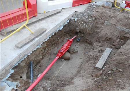
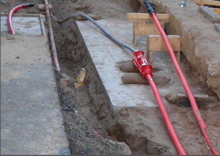
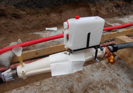
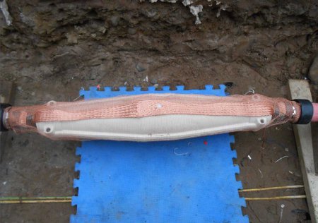
Lovink
Lovink manufactured cable joints are approved by UK DNO’s, including Western Power Distribution, for 11kV medium voltage straight, stop-ends, branch and loop joints.

Jointers blog
Subscribe now to our POWER NEWSLETTER– a monthly email circulation packed with news, projects, videos, technical tips, training information, promotions, webinars, career opportunities and white papers.
Includes access to our popular JOINTERS BLOG with contributions from utility professionals, linesmen and cable jointers working on MV HV EHV cables and overhead lines typically at 11kV, 33kV, 66kV and up to 132kV.
15,000+ Subscribers. ➡ 


