Extract from : Company Directive | STANDARD TECHNIQUE : SP1N
Owner : UK DNO Western Power Distribution
Sealing Cable Entries
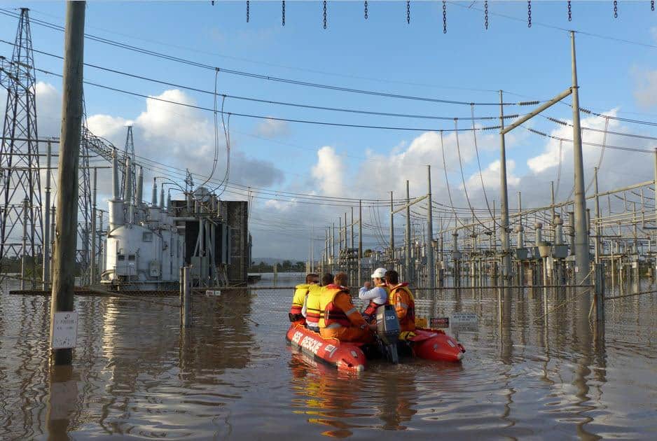
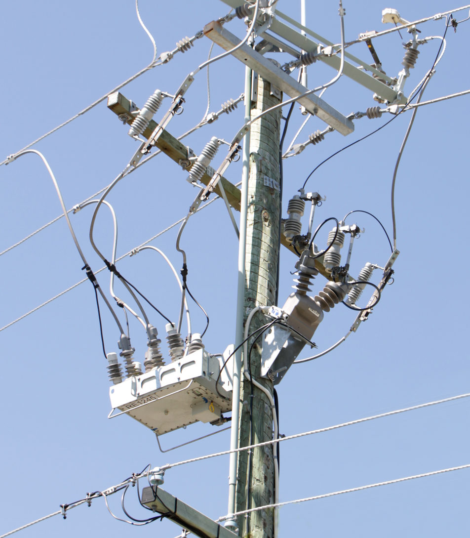
In the UK the DNO’s (Distribution Network Operator) hold a statutory requirement to prevent danger due to the influx of water, or any noxious or explosive liquid, hydrocarbon or gas from the surrounding ground into substations, street boxes and buildings. The electric utility will have an approved method and material to seal ducts in all new, altered or retro-fitted cable installations – this includes the sealing of cable ducts where the ducting enters the switch gear building. View our complete range of UK DNO Specification & Private Networkduct seals.
Thorne & Derrick
T&D are Specialist Distributors to UK Distribution Network Operators (DNO’s), NERS Registered Service Providers, ICP’s and HV Jointing Contractors of an extensive range of LV, MV & HV Jointing, Earthing, Substation & Electrical Eqpt– this includes 11kV/33kV/66kV cable joints, terminations and connectors for both DNO and private network applications.
Contact our UK Power Team for competitive quotations, fast delivery from stock and technical support or training on all LV-HV products.
All international sales enquiries can be serviced and supplied by our Export Power Team.
Uploaded by Chris Dodds - Thorne & Derrick Sales & Marketing Manager
Cembre HT131-C
Thorne & Derrick International are Main UK Stockists and Suppliers of Cembre tools including crimping and cutting types for all constructions of LV MV HV cable including medium/high voltage 11kV/33kV power cables.
The following short article provides useful information about maintaining optimum performance of the Cembre model HT131-C crimping tool.
Cembre HT131-C crimping tool is lightweight and ideal for LV-HV cable jointing, crimping, splicing and terminating applications.
The hydraulic crimping tool features spring loaded handles allowing the Cembre die sets to be advanced with one hand – the other hand free to position the electrical connector or cable lugs prior to crimping.
For competitive prices, stock availability and technical advice about the Cembre HT131-C tool please do not hesitate to contact us.
Maintaining Crimping Tool Optimum Performance – Model Cembre HT131-C
The Cembre HT131-C hydraulic crimping tool is robust and requires very little daily maintenance – ensuring you follow the instructions below will help to maintain the optimum performance of the tool:
Accurate Crimping Tool Cleaning
Dust, sand and dirt are a danger for any hydraulic device. It is essential that after every use the crimping tool should be wiped with a clean cloth removing all residue paying special attention to pivots and moveable joints
Tool Storage
Cembre HT131-C is supplied with VAL P3 plastic case.
When not in use, the HT131-C tool should be stored and transported in the plastic case to prevent damage.
The plastic case (Type VAL P3) has the following dimensions 620x380x135mm (height) and weighs 2.5 kg.
Air in the hydraulic circuit may affect the performance of the crimping tool. For example no lower die advancement, slow advancement of the lower die and lower die pulsating would all cause issues. If this is the case proceed as follows:
To Purge Air Bubbles From Hydraulic Circuit
Fig 4 – HT131-C Crimping Tool Position For Maintenance Operations
a – Hold tool upright in a vice with handles open (Fig 4)
b – By an hexagonal 2.5 mm key, remove screw (65) and main handle (04) to expose oil reservoir (03).
c – Remove reservoir cap (01).
d – Operate three or four times the moveable handle (56), to advance the ram (28).
e – Depress pressure release pin (73) until ram is fully retracted.
f – Repeat points (d – e) at least five times,to ensure all air bubbles in the hydraulic circuit are purged into the reservoir.
g – If the oil level is low top as described below
h – Remove all air from reservoir and fit cap (01).
i – Assemble main handle (04), and holding screw (65).
If the tool continues to malfunction return the tool for service.
Oil Top Up
Every six months check the oil level in the reservoir. If necessary, top up the oil level to the upper lip of the reservoir and remove all air from the reservoir (as described above).
Hydraulic or Battery Operated Crimping Tools
Cembre B1300-CE battery crimping tool is an 18.0V cordless hydraulic crimping tool which can be operated with one hand and is balanced for greater control – this tool is the battery operated version of the Cembre HT131-C with a crimping and compression range up to 400sqmm for LVand MV cables up to 33kV.
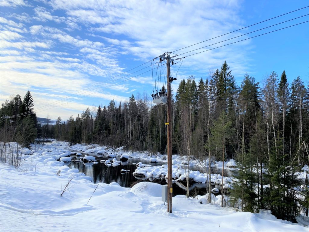
Special Thanks To Alex Veselov At Noja Power For The Above Image
My partners in Sweden just shared some great pictures of OSM27-SEF NOJA Power Reclosers surrounded by nice winter nature. Swedish 20kV distribution network has isolated neutral and therefore very low earth fault currents. This is where a special SEF (Sensitive Earth Fault) version of OSM27 can help as it works from as little as 0.2 A fault currents. View the NOJA Power OSM Automatic Circuit Recloser 15kV 27kV 38kV download.
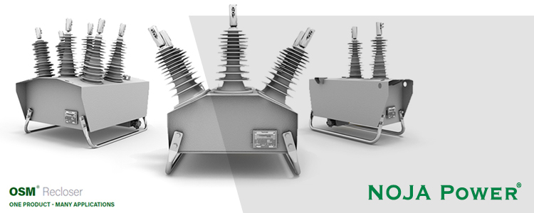
The OSM15, OSM27 and OSM38 automatic circuit reclosers incorporate vacuum interrupters inside solid dielectric insulated poles which are housed within the arc fault venting designed, stainless steel tank. This ensures maximum life and reliability with a fully insulated arrangement inside the long life housing.
NOJA Power
NOJA Power is a world leading manufacturer of Medium Voltage Electrical Equipment.
With more than 64,000 OSM units installed in over 92 countries, our SF6 Free equipment is essential to the future of electricity distribution.
We offer our customers integrated solutions using innovative products combined with unrivalled service and reliability world wide.
We specialise in Medium Voltage Outdoor Switchgear, covering applications such as overhead lines protection, substations, renewable, distributed generation connection & underground cable protection.
Thorne & Derrick
T&D are Specialist Distributors to UK Distribution Network Operators (DNO’s), NERS Registered Service Providers, ICP’s and HV Jointing Contractors of an extensive range of LV, MV & HV Jointing, Earthing, Substation & Electrical Eqpt– this includes 11kV/33kV/66kV cable joints, terminations and connectors for both DNO and private network applications.
Contact our UK Power Team for competitive quotations, fast delivery from stock and technical support or training on all LV-HV products.
All international sales enquiries can be serviced and supplied by our Export Power Team.
High Voltage Enabling Works at Bryn Pica Eco Park Development
High Voltage Enabling Works
Special Thanks To Tristian Jones For His Kind Permission To Republish
C&P’s high voltage company,C&P High Voltage Serviceshave been busy this week completing the 1st phase of construction of a high voltage ring for the future development of a multi-million-pound Eco Park development for Rhondda Cynon Taf Council – the facility will be the first of its kind in the UK.
Once completed the electrical infrastructure will be extended into phase 2 to supply further factory buildings for future recycled materials production.
C&P High Voltage services division will provide enabling works which includes design, supply, install, test and commissioning for a 2MVA package substation, Ring Main Unit (RMU), HV cable system for a 2MVA package substation, Low Voltage (LV) cable system for Mattress recycling, visitor centre fence distribution board, feeder pillar to replace perimeter fence distribution board and Low Voltage (LV) cable transfers.
This week a smartfeeder pillarwas installed, along with a 2MVA transformer and RN2D close coupled RMU with VIP protection on the circuit breaker. This will allow for remote monitoring and operation through a BMS or website control platform.
Eco Park Development – which would be the first of its kind in the UK
Over the past 18-months C&P has been rapidly expanding its high voltage services and maintenance activities, securing a number of critical projects and contracts across the UK.
David Demock, C&P’s High Voltage Engineering Director commented: “We are extremely pleased to partner with Rhondda Cynon Taf County Borough Council to deliver such an important phase for this prestigious project. We have been adding to our power engineering capabilities over the past few years which has assisted us to grow and offer clients such as Rhondda Cynon Taf Council even more value through our unique approach.
Using our own people, plant and highly experienced engineering solutions we are pleased that we can play a vital role in the development of the park. This will ultimately help to recycle more, protect the environment and create commercial opportunities and job creation in the Cynon Valley”.
About C&P High Voltage Services
C&P High Voltage Services provide a full range of high voltage electrical contracting services across a diverse range of customers. Their full turnkey high voltage engineering services cover design, installation, testing, commissioning, energisation, operation and maintenance for both new high voltage electrical installation and refurbishments for private networks up to and including 132kV.
Thorne & Derrick International are specialist distributors of LV, MV & HV Cable Installation, Jointing, Duct Sealing, Substation & Electrical Equipment – servicing UK and global businesses involved in cable installations, cable jointing, substation, overhead line and electrical construction at LV, 11kV, 33kV and EHV.
The following article on Cable Asset Management has been published with the kind permission of ERPA.
ERPA (Electric Power Reliability Alliance) are a collaborative practitioner community that works to advance awareness and understanding of electric power reliability.
ERPA are a “practitioner-to-practitioner” collaborative community, bringing proven and practical resources and shared experiences to practitioners in the industrial and commercial markets.
A reliable power system is the lifeblood of any production facility, distribution system, data center or business.
Join a growing community of industrial and commercial electric power reliability practitioners.
Cable Asset Management
A Scientific Approach to Cable Asset Management
By Ben Lanz, Director, Applications Engineering, IMCORP. Member, EPRA
Power Cables | Cable Care
Power cables are one of the most commonly overlooked power system assets and are, by default, typically addressed reactively after failure. They are also one of the most misunderstood. This article provides insight into how new scientific findings on cable care address these misunderstandings. In this article I will provide insight into some of these findings through case studies, and I’ll explain how a holistic, condition intelligence-based strategy can easily double the expected life of most assets — including cables — and maximize reliability with optimal life cycle cost.
Most medium- and high-voltage cable systems consist of plastic and rubber (solid dielectric) insulation. A significant percentage of assets containing those materials are reaching—or have passed—their assumed 30- to 40-year end-of-life. Asset managers are now facing a significant challenge in balancing reliable power delivery with budget priorities. As new assets are installed, reliability professionals are asking, “how can we make cable systems last longer with higher reliability?”
Cable Asset Management Best Practices
This broad reliability question comprises several smaller and more practical questions, which have been answered here with input from cable owners from all over the world. With their help, we have assembled the largest condition assessment database of its kind—and the findings are good news for cable owners.
We discovered that to extend the life of medium and high voltage cables, there are two key things to consider when developing a reliability plan, supported by four best-practice recommendations:
A. Practice “cable care” techniques.
With the proper care and maintenance, aged cable systems can outperform new cable systems.
B. Eliminate physical stressors and extreme duty stressors.
With these additional stressors removed, it is possible to extend the reliable life of cable to 100 years— and beyond.
C. Follow best practices
Install and maintain over voltage protection.
Perform IR inspection of connectors.
Perform offline 50/60Hz PD testing to ID insulation defects.
Eliminate or minimize over voltage tests such as fault location ‘thumping’ and withstand/hipot testing.
Medium and high voltage solid dielectric cable system insulation fails due to an erosion process associated with phenomena called partial discharge (PD).
PD is an electrical discharge (or ‘micro arcing’) that does not completely bridge the insulation. PD can arise from an extreme focus of electric stress, a lack of the appropriate solid insulation, or a combination of both.
A focus of electric stress, or stress enhancement, can be caused by issues such as accessory interface contamination, a foreign object, a protrusion of a semiconducting layer, or area of extreme moisture concentration. A lack of appropriate solid insulation filled by a gas, or a void, can be caused by such issues as:
a damaged semiconducting layer
overheating of the cable or accessory insulation
an insulation cut
a lack of accessory/cable interface void filler
or an incorrect accessory/cable interface dimension
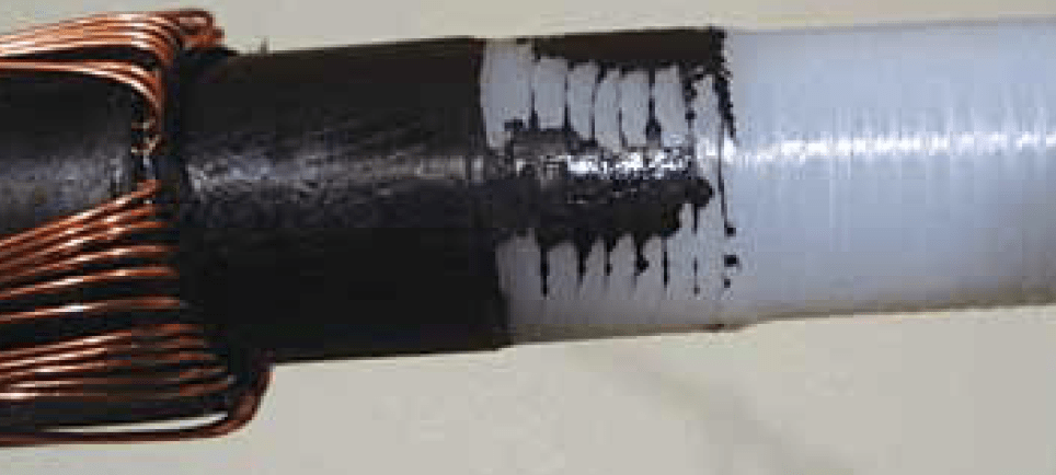
Failure to use correct jointing tools can lead to catastrophic cable failures at the connection interface of cables (straight joints) or at their ends (cable terminations) – core screen thickness and strippability varies from cable to cable manufacturer therefore it is essential for the MV-HV cable jointer to set the cutting blade of the cable tool to the correct screen cutting depth, this is usually tested on scrap cable lengths prior to jointing.
PD, and its associated erosion process at a defect site, is rarely active at steady-state operating voltage unless the failure is imminent. PD is initiated when localized electric stress overcomes the local dielectric strength.
Voltage transients—fast, short duration electrical transients—are the primary driver to turn on PD and propagate insulation failure. The sources of transients include:
circuit switching
restoration activities, such as breaker operations and fuse re closures
fault location and withstand tests
momentary flashovers and grounds (momentary contacts with air insulated components)
complete faults elsewhere in the system
sectionalizers
capacitor banks switching
transformer tap changes
and, especially, lightning
Transients reflect and resonate within the power system and can increase in magnitude exponentially. Voltage transients typically occur in the microsecond to millisecond time frame. This is more than enough time for PD, which occurs in the nanosecond range, to turn on, erode the insulation, and turn off.
Successive transients can cause intermittent growth of a carbonized fault channel sometimes described as an electrical tree. As the electrical tree grows, the turn-on voltage drops, and eventually the PD is active at the operating voltage. The erosion process fails this insulation.
Industry Questions Answered with Science
Many questions have been asked about proper cable care over the last few decades. These questions have often been answered with reasonable theories, which have helped the industry make reasonably accurate asset decisions. But now, with the aid of scientific research, a more precise understanding is driving more optimal solutions.
Answers to some of those frequently asked questions now follow, and each is informed by this research:
D. Does cable only last 30 to 40 years?
Research indicates for most applications, provided there is no extreme loading or voltage events or discrete physical defects in the cable system, there are no known significant long-term aging mechanisms to cause cables to fail short of 100 or more years.
E. Does moisture fail cable?
No. Random moisture only creates a more ‘leaky’ or lossy insulation. Aside from losing a tiny amount of power to operate the cable, this is not problem.
However, in the extremely rare event that moisture concentrates due to the higher stress of an original manufacturing or installation defect, extreme voltage transient can cause local stresses to exceed the insulation strength, start carbonizing insulation, and creating a fault channel (electrical treeing).
F. Does cable fail rapidly once a carbon track is formed?
In the vast majority of cases, No. Most carbon tracks or ‘electrical trees’ are not active at the operating voltage and thus only grow during short voltage transients. They can take years—or even decades—to grow to failure.
G. Do installation defects fail quickly?
Installation defects often take years or decades to fail. Since the defect erosion process is only turned on intermittently and the fault channel path is driven by the highest stress path which often is not the shortest path, the growth rate can be surprisingly slow. The first failure is often associated with an installation or manufacturing defect. However, once a cable is a couple of decades old, we need to be
very careful as the voltage transients associated with the fault location process often damages the cable causing new defects.
H. Can DC or VLF tests at least detect most of the gross defects?
DC and VLF (very low frequency or 0.1Hz) present such different stress distributions in cable insulation compared to in-service and factory test conditions, most defects are missed. By adding dielectric loss or tangent delta measurements—or even PD measurements—a few more percent of defects can be detected.
That said, these approaches are generally less than a ten percent solution and unfortunately can cause damage without warning. Best practice recommends, these tests be kept to less than the line to ground voltage for less than a minute just to check for existing shorts.
I. Are most cable failures due to overheating?
Overheating is generally a connector problem, not a cable issue. Most failures are actually due to insulation defects, not overheating problems. However, in high load applications, termination and joint connector installation problems on aluminum conductors are notorious for overheating and damaging cable insulation systems.
J. Is helical copper tape a robust shield design?
Helical copper tape functions just fine in paper insulated cable systems, since it is in oil and moisture is kept out by a lead sheath. Solid dielectric cable only has a polymer jacket to protect it and does not stop moisture from causing corrosion, initializing a process of arcing and pitting from the outside inwards which is commonly observed on aged cable.
Generally concentric neutral and longitudinally applied copper tapes have been shown to have a much better long-term performance.
K. Are there any standards we can use test solid dielectric cable systems?
Quality tests by cable and accessory manufacturers are performed on all new system components at the manufacturing plant prior to shipping and installation. All factory-built products must meet standards such as ICEA (Insulated Cable Engineers Association) or IEEE (Institute of Electrical and Electronics Engineers).
The manufacturers’ quality control tests require 50/60Hz partial discharge (PD) diagnostics at an elevated voltage, with generally better than 5 or 10pC sensitivity [Table 1]. These standards can be used to judge the performance of cable system in the field.
L. What can be done to enhance longevity?
The recipe for cable longevity is to push quality to the earliest point in the life of the cable system, and then minimize any extreme duty cycle events. As early in life as possible a cable system should be baselined with an offline 50/60Hz PD test to check for insulation issues and an IR test under high load conditions to check for connector issues.
Once any necessary repairs are complete, confirm sufficient over-voltage protection is installed at all significant impedance change points (primary cable end points). Finally, monitor the cable system for any extreme over-voltage or overloading events (including, re closing on faults, thumping, withstand or Hipot testing). If such events occur, a new baseline for the insulation and connector will need to be established.
Thorne & Derrick International are specialist distributors of LV, MV & HV Cable Installation, Jointing, Duct Sealing, Substation & Electrical Equipment – servicing UK and global businesses involved in cable installations, cable jointing, substation, overhead line and electrical construction at LV, 11kV, 33kV and EHV.