

- Ensuring Optimum Performance Of Cembre Crimping Tool – Model HT131-C
- Cembre Cutting Tools Instructions For Use – Model B-TC950
- Cembre B1350-CE v. B135-C Crimping Tools Performance Comparison
- Replacing Cembre Cable Cutting Tool Blades – Model HT-TC051
- Maintenance For Cembre Cable Cutting Tool – Model HT-TC051
Blog
Selecting & Positioning Dies In Cembre ECW-H3D Presshead Tool
June 13th, 2018
Cembre ECW-H3D Presshead Die Sets
-
Uploaded by Chris Dodds - Thorne & Derrick Sales & Marketing Manager
Cembre ECW-H3D
Thorne & Derrick International are Main UK Stockists and Suppliers of Cembre tools including crimping and cutting types for all constructions of LV MV HV cable including medium/high voltage 11kV/33kV power cables.
The following short article provides useful instructions about how to correctly select and position dies in the Cembre presshead model ECW-H3D – the tool is used primarily to joint and terminate lugs or connectors on LV MV HV cables including 11kV/33kV medium/high voltage electrical systems with a range of 500-630sqmm conductors.
The following excerpts are taken from the Operating Manual of Cembre ECW-H3D hydraulic presshead crimping tool.
Cembre ECW-H3D comes complete with complete with male quick automatic coupler for connection to a hydraulic pump with a working pressure of 10,000 psi max.
For competitive prices, stock availability and technical advice about the Cembre ECW-H3D tool please do not hesitate to contact us.
Cembre ECW-H3D
Selecting & Positioning Die Sets

Fig 1 Die Assembly & Positioning
Die Assembly (Fig 1)
- Dedicated Dies
- Select the appropriate die set for the connector to be crimped using ECW-H3D tool
- Extract the die retaining pin (09) from the tool head
- Insert the lower die (26b) and align the groove (30) in the die, with the guide pins (15) in the crimp tool presshead
- Insert the upper die (26a) into the tool head
- Insert the die retaining pin (09) in the head and through the upper die. Ensure the spring loaded pin (10) is fully released
- Semi-circular Dies
- Select the appropriate die set for the connector to be crimped using ECW-H3D tool
- Extract the die retaining pin (09) from the tool head
- Insert the lower half of adapter Cembre AU230-130D (31b) and align the groove (30) in the adapter, with the guide pins (15) in the head
- Insert the upper half of the adapter Cembre AU230-130D (31a) into the head
- Insert the die retaining pin (09) into the head and through the adapter. Ensure the spring loaded pin (10) is fully released
- Press pin (35) on lower part of adapter, AU230-130D and insert one half of the die set until secured by locking pin (34)
- Press pin (32) on upper half of adapter, AU230-130D and insert the other half of the die set until secured by locking pin (33)
♦ Warning: Before carrying out further operations make sure the die-stop pin is completely inserted; a partial insertion may cause damage to the head.
Dies Positioning
- Insert the conductor into the connector.
- Locate the connector between the dies at the desired crimp position. – Operate the pump until the dies touch the connector barrel
♦ Warning: Make sure that dies are exactly positioned on the area to be crimped; otherwise re-open dies and reposition the connector.

LV Lugs & Connectors – complete range of copper crimp connectors suitable for use with joints and terminations for low voltage cables | Cable Lugs | Cable Splice Connectors | Aluminium Lugs | Aluminium Splices | Bi-Metallic Cable Lugs

Cutting & Crimping Tools
Cable Crimping & Cutting Tools
This post is from a series of articles written to provide advice and guidance on the care and servicing of Cembre cable cutting and crimping tools.

HV Lugs & Connectors – complete range of copper crimp connectors suitable for use with joints and terminations for medium/high voltage cables | Cable Lugs | Transformer Lugs | 2 Hole Lugs | Pin Stalk Connectors | Through Connectors | 11kV 33kV
Thorne & Derrick
Key Product Categories: Duct Seals | Cable Cleats | Cable Glands | Electrical Safety | Arc Flash Protection | Cable Jointing Tools | Cable Pulling | Earthing | Feeder Pillars | Cable Joints LV | Joints & Terminations MV HV | Cold Shrink
Replacing Cembre Cable Cutting Tool Blades – Model TC055
June 13th, 2018
Cembre TC055 Cutting Head
-
Uploaded by Chris Dodds - Thorne & Derrick Sales & Marketing Manager
Cembre TC055
Thorne & Derrick International are Main UK Stockists and Suppliers of Cembre tools including crimping and cutting types for all constructions of LV MV HV cable including medium/high voltage 11kV/33kV power cables.
The following short article provides useful instructions about how to replace the cable cutting tool blades of the Cembre TC055 – this cutter has an application range suitable for cutting copper and aluminium cables having a maximum diameter of 55mm.
Note: TC055 cutting head features the same cutting capability as the Cembre HT-TC055 cable cutting tool.
The following excerpts are taken from the Operating Manual of Cembre TC055.
Cembre TC055 is a hydraulic cutting head tool developing a maximum pressure of 10,000 psi for cable and conductor cutting of LV MV HV cables.
For competitive prices, stock availability and technical advice about the Cembre HT-TC055 tool please do not hesitate to contact us.
Cable Cutting Blade Replacement
Cembre TC055

Fig 2 & Fig 3 Cembre TC055 Blade Replacement
The following instructions should be read in conjunction with the image above.
After extended use the blades of the Cembre TC055 may lose their cutting edge.
Replace the blades as follows:
Lower Cable Cutting Blade
Remove locking pin (4) and open the cutting tool head.
Operate the pump to advance the lower cutter blade (24) until split pins (22 and 23) are visible on the ram (18).
Remove split pins (22 and 23) using a drift and remove the lower cutter blade.
Insert the new blade and secure with spring pins.
♦ Warning: Before closing the cutting tool head release the oil pressure and retract the lower cutter blade otherwise the blade may hit the lower blade edge and damage it.
Upper Cable Cutting Blade
With the lower cutter blade fully retracted, the tool head closed and the locking pin (4) fully secured, hold the tool on the blade spacer (1) or (26) in a bench vice (Fig 3).
With a 6mm wrench, unscrew 4 screws (28), remove the two holding plates (29) and the upper cutter blade (25) noting the position of the cutting edge bevel.
Insert the new cutting blade, noting the position of the cutting edge bevel.
Fit the 2 holding plates (29) and secure with 4 screws (28) with relevant washer (30).
LV Lugs & Connectors – complete range of copper crimp connectors suitable for use with joints and terminations for low voltage cables | Cable Lugs | Cable Splice Connectors | Aluminium Lugs | Aluminium Splices | Bi-Metallic Cable Lugs
Cutting & Crimping Tools
Cable Crimping & Cutting Tools
This post is from a series of articles written to provide advice and guidance on the care and servicing of Cembre cable cutting and crimping tools.
- Ensuring Optimum Performance Of Cembre Crimping Tool – Model HT131-C
- Cembre Cutting Tools Instructions For Use – Model B-TC950
- Cembre B1350-CE v. B135-C Crimping Tools Performance Comparison
- Replacing Cembre Cable Cutting Tool Blades – Model HT-TC051
- Maintenance For Cembre Cable Cutting Tool – Model HT-TC051
HV Lugs & Connectors – complete range of copper crimp connectors suitable for use with joints and terminations for medium/high voltage cables | Cable Lugs | Transformer Lugs | 2 Hole Lugs | Pin Stalk Connectors | Through Connectors | 11kV 33kV
Thorne & Derrick
Key Product Categories: Duct Seals | Cable Cleats | Cable Glands | Electrical Safety | Arc Flash Protection | Cable Jointing Tools | Cable Pulling | Earthing | Feeder Pillars | Cable Joints LV | Joints & Terminations MV HV | Cold Shrink
Maintenance Of Flexible Hose In Cembre PO7000 Hydraulic Pump
June 13th, 2018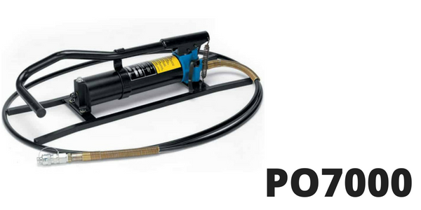
Cembre PO7000 Hydraulic Foot Pump
-
Uploaded by Chris Dodds - Thorne & Derrick Sales & Marketing Manager
Thorne & Derrick International are Main UK Stockists and Suppliers of Cembre tools including crimping and cutting types for all constructions of LV MV HV cable including medium/high voltage 11kV/33kV power cables.
The following short article provides useful instructions about how to correctly maintain the flexible hose in the Cembre hydraulic PO7000 hydraulic pump – supplied with 10 foot long high pressure flexible hose complete with an automatic, female, quick-coupler suitable for connection to a Cembre hydraulic crimping or cutting head.
The following excerpts are taken from the Operating Manual of Cembre PO700.
Cembre PO700 is a foot operated double speed hydraulic pump developing a maximum pressure of 10,000 psi for installing cable crimps, lugs and connectors.
Maintenance Of Flexible Hose

Cembre PO7000 Pump stored in plastic case VAL-P21.
The flexible hose is designed for high-pressure operation and should not be tightly bent, knotted, kinked or squashed.
♦ Warning: Take care when storing the pump in the plastic case, the hose should be coiled in wide loops.
High pressure flexible hoses are subject to a natural ageing process which can result in a reduction in performance potentially affecting safety of the operator and functionality of the hydraulic pump. In order to ensure safe use of the PO7000, Cembre recommends replacing the hose within 10 years from the date printed on the tool fittings. Pumps in the PO7000 range are supplied with a standard or non-conductive hose.
♦ Warning: Before using the pump always check the integrity of the flexible hose and the quick couplers making sure there are no abrasions, cuts, deformations or swellings.
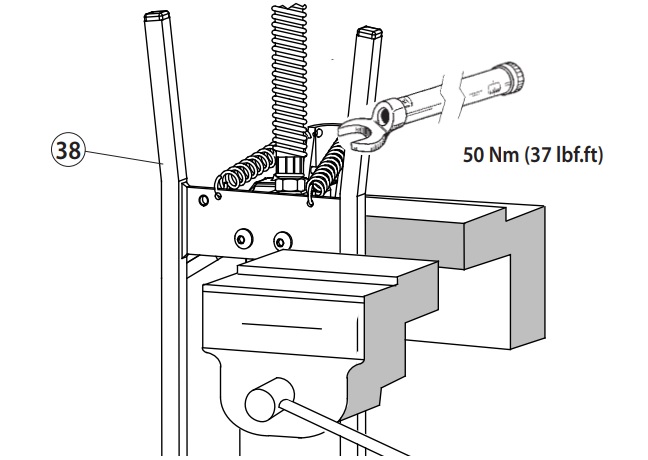
Fig 8 Hydraulic Pump Position For Replacement Of High Pressure Hose
Replacement Of The Pressure Hose
- Hold the pump base (38) in a vice, keeping the hose above the level of the vice
- Using a 19 mm fl at spanner, unscrew the hose from the pump body, while holding the coiled hose
- Carefully clean the thread of the pump body to remove any residual sealing materials
- Restore the gasket (tefl on tape) on the (male) thread of the new hose
- Connect the new hose, tightening the relevant nut to the correct torque ratio: 50 Nm (37 lbf.ft)
- Eliminate air in the hose as follows: unlock the pedal from the latch
- Depress the ball of the female quick coupler fitted to the end of the hose and pump slowly several times, until the oil flows
- Check the oil level and top up as described in operating manual
Cutting & Crimping Tools
Cable Crimping & Cutting Tools
This post is from a series of articles written to provide advice and guidance on the care and servicing of Cembre cable cutting and crimping tools.
- Ensuring Optimum Performance Of Cembre Crimping Tool – Model HT131-C
- Cembre Cutting Tools Instructions For Use – Model B-TC950
- Cembre B1350-CE v. B135-C Crimping Tools Performance Comparison
- Replacing Cembre Cable Cutting Tool Blades – Model HT-TC051
- Maintenance For Cembre Cable Cutting Tool – Model HT-TC051
Thorne & Derrick
Key Product Categories: Duct Seals | Cable Cleats | Cable Glands | Electrical Safety | Arc Flash Protection | Cable Jointing Tools | Cable Pulling | Earthing | Feeder Pillars | Cable Joints LV | Joints & Terminations MV HV | Cold Shrink
How to Correctly Clean & Store Cembre TC120 Cable Cutting Tool
June 13th, 2018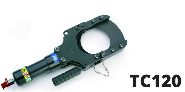
Cembre TC120 Cutting Head
-
Uploaded by Chris Dodds - Thorne & Derrick Sales & Marketing Manager
Cembre TC120
Thorne & Derrick International are Main UK Stockists and Suppliers of Cembre tools including crimping and cutting types for all constructions of LV MV HV cable including medium/high voltage 11kV/33kV power cables.
The following short article provides useful instructions about how to correctly clean and store the Cembre model TC120 cutting head – the head is designed for cutting copper, aluminium and telephone cables having a maximum diameter of 120mm.
♦ Warning: Do not attempt to cut steel ropes or steel reinforced cables (ACSR)
For competitive prices, stock availability and technical advice about the Cembre TC120 tool please do not hesitate to contact us.
Cembre TC120
How to Correctly Clean & Store
Cutting Tool Storage

Cembre TC120 provided with a special steel case VAL 120 to safely transport the cutting head and prevent damage
♦ Warning: Oil pressure inside the TC120 cutting head must always be completely released before disconnecting the head from the hose.
♦ Warning: All maintenance operations must be performed with the head disconnected from the hydraulic pump hose.
The Cembre TC120 cutting head is robust and requires very little daily maintenance – ensuring you follow the instructions below will help to maintain the optimum performance of the tool by cleaning and storing correctly:
Accurate Cutting Head Cleaning
Dust, sand and dirt are a danger for any hydraulic device. It is essential that after every use the cable crimping or cutting tool should be wiped with a clean cloth removing all residue paying special attention to pivots and moveable joints
Replacement Of The Automatic Quick Male Coupler
- To replace the automatic coupler from Cembre TC120 proceed as follows:
- Remove the old coupler.
- Carefully clean the thread to remove old sealant.
- Apply teflon tape to the thread.
- Fit the new coupler and tighten to 30 Nm (22 lbf ft)
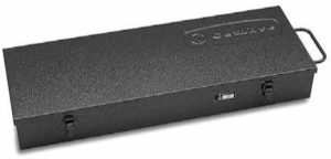
Steel Carry Case VAL TC120
Storage
When not in use, the Cembre TC120 tool should be stored and transported in the steel case to prevent damage.
The steel case (VAL TC120) has the following dimensions 590x209x84mm (height) and weighs 4.9kg.
LV Lugs & Connectors – complete range of copper crimp connectors suitable for use with joints and terminations for low voltage cables | Cable Lugs | Cable Splice Connectors | Aluminium Lugs | Aluminium Splices | Bi-Metallic Cable Lugs
Cutting & Crimping Tools
Cable Crimping & Cutting Tools
This post is from a series of articles written to provide advice and guidance on the care and servicing of Cembre cable cutting and crimping tools.
- Ensuring Optimum Performance Of Cembre Crimping Tool – Model HT131-C
- Cembre Cutting Tools Instructions For Use – Model B-TC950
- Cembre B1350-CE v. B135-C Crimping Tools Performance Comparison
- Replacing Cembre Cable Cutting Tool Blades – Model HT-TC051
- Maintenance For Cembre Cable Cutting Tool – Model HT-TC051
HV Lugs & Connectors – complete range of copper crimp connectors suitable for use with joints and terminations for medium/high voltage cables | Cable Lugs | Transformer Lugs | 2 Hole Lugs | Pin Stalk Connectors | Through Connectors | 11kV 33kV
Thorne & Derrick
Key Product Categories: Duct Seals | Cable Cleats | Cable Glands | Electrical Safety | Arc Flash Protection | Cable Jointing Tools | Cable Pulling | Earthing | Feeder Pillars | Cable Joints LV | Joints & Terminations MV HV | Cold Shrink
ASTM D120 Insulating Gloves
June 12th, 2018
-
uploaded by Chris Dodds - Thorne & Derrick
ASTM D120 specification covers manufacturing and testing of rubber insulating gloves for protection of workers from electrical shock.
Two types of insulating gloves are provided and are designated as Type I, non-resistant to ozone, and Type II, resistant to ozone.
Six classes of ASTM D120 compliant insulating gloves differing in electrical characteristics are provided and are designated as Class 00, Class 0, Class 1, Class 2, Class 3 and Class 4.
The following tests shall be performed as part of the ASTM D120 Standard Specification for Rubber Insulating Gloves:
- ac proof test
- ac breakdown test
- ac moisture absorption/proof test
- dc proof test
- dc breakdown test
- ozone resistance test
- chemical tests
- tensile strength
- tear resistance test
- puncture resistance test
This following abstract is a brief summary of the referenced ASTM D120 standard – this is provided for informational purposes only and not an official part of the ASTM D120 standard; the full text of the standard itself must be referred to for its use and application.
ASTM does not give any warranty express or implied or make any representation that the contents of this abstract are accurate, complete or up to date.
Scope Of ASTM D120
1.1 This specification covers manufacturing and testing of rubber insulating gloves for protection of workers from electrical shock
1.2 Two types of gloves are provided and are designated as Type I, non-resistant to ozone, and Type II, resistant to ozone
1.3 6 classes of insulating gloves each differing in electrical characteristics are provided and are designated as Class 00, Class 0, Class 1, Class 2, Class 3, and Class 4
1.4 The values stated in SI units are to be regarded as standard. See IEEE/ASTM SI 10
1.5 The following safety hazards caveat pertains only to the test method portion, Sections 16, 17, 18, and 19, of this specification. This standard does not purport to address all of the safety concerns, if any, associated with its use. It is the responsibility of the user of this standard to establish appropriate safety and health practices and determine the applicability of regulatory limitations prior to use.
Insulating Gloves
The following table enables the selection of ASTM D120 Insulating Gloves according to working voltage and insulating class category – should you require any assistance with the correct type, specification or size of gloves please do not hesitate to contact us.
| CATU Electrical Code | Insulating Glove Class | Voltage | Type | Inches | Colour |
| CATU CGA-00 | Class 00 | ≤ 500V | 1 | 14 | Black |
| CATU CGA-0 | Class 0 | ≤ 1000V | 1 | 14 | Black |
| CATU CGA-1 | Class 1 | ≤ 7500V | 1 | 14 | Bi-Colour |
| CATU CGA-2 | Class 2 | ≤ 17000V | 1 | 14 | Bi-Colour |
| CATU CGA-3 | Class 3 | ≤ 26500V | 1 | 14 | Bi-Colour |
| CATU CGA-4 | Class 4 | ≤ 36000V | 1 | 16 | Bi-Colour |




