

Blog
Electrical Safety – Arc Flash Accidents & Electrocution In LV-HV Installations
November 12th, 2017
10 Things You Should Know About Electrical Safety & Protection | Image ABB
by Chris Dodds T&D - estimated reading time 5 minutes

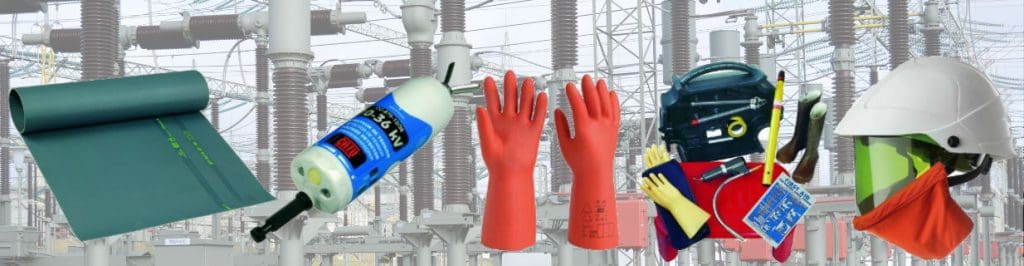
T&D Largest UK Stockist – CATU Electrical Safety Equipment For LV HV EHV Electricity Cables, Lines & Substations
The world of electrical safety, insulation and protection is rife with potential hazards and dangers. Electrocution risks prevail throughout low and high voltage power systems – whether by underground cable or via overhead line where the ampere flows danger goes with it.
Electrical Safety Foundation International has confirmed every 30 minutes during the work day, a worker suffers an electrically induced injury that requires time off the job for recovery.
Over the last ten years, more than 46,000 workers have been injured from on-the-job electrical hazards.
Engineers, installers, maintenance and other operatives working on or near HV and LV electrical installations are at risk from the dangers an arc flash, power surge or short circuit can cause.
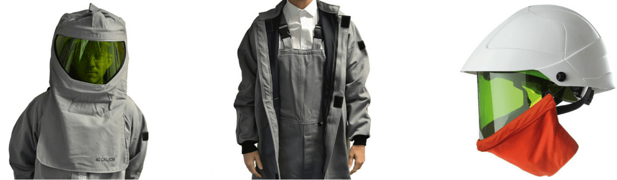
Arc flash clothing is essential to provide “head-to-toe” worker protection against arc incidents – this includes a complete range of arc flash gloves, arc flash helmets and garments for utility workers carrying out installation and maintenance tasks on LV MV HV underground cables, overhead lines and electrical substation equipment.
Cable jointers working on underground cables, linesmen stringing overhead conductors and SAP’s switching high voltage substations all confront daily dangers of electrocution which can only be moderated by a responsible attitude to electrical safety and risk assessment.
In a seperate post we have covered the all too real risk of cable jointers exposed to arc flash risk.
T&D World Magazine authored the following thought provoking article : Utility Line Workers: One of the Top 10 Most Dangerous Professions
Nothing has changed. Serious injury, high degree burns, electrocution and all to commonly death are the dangers that face these workers daily if the proper electrical safety precautions are not taken.
Here, we take a look at 10 of the most important factors that need to be considered regarding LV-HV Electrical Safety.
The list below is by no means exhaustive, however it does cover 10 of the most pertinent points that must be considered prior to carrying out any electrical installation, maintenance or other work:
- Arc Flash – calculation, risk assessment, protection and dangers
- Electrical Accidents – causes, courses and cable faults
- Electrical Isolation – what is lock-out tag-out?
- Electrical Accidents – prevention and risk assessment
- Arc Flash Protection – eliminating, reducing and quenching
- British Standards – domestic electrical protection and BS7671
- Partial Discharge – high voltage power systems and cable breakdown
- Electrical Equipment – correct use and selection
- Safe Working – 4 steps towards electrical safety
- Dead or Live – energised or de-energised electrical working

Image: Jim McDonald (Owner/Live Line Training at Powerline Training Consultants)
1. Arc Flash
The most common hazards typically faced when working on LV HV electrical cables, switchgear and substation installations are electrical arcing (often called a ‘flashover’ or ‘arc flash’).
♦ Arc Flash Statistic: According to NFPA and IEEE from 1992 to 2002, over 2,000 workers a year or more than 5 workers a day were victims of an arc flash.
Arc flash can generate intense levels of heat and flames which can cause deep set burns and serious injury. The dangers of arc flash incidents are well documented and calculating the potential level and power of an electrical arc to provide adequate arc flash protective clothing can save lives should an arc flash incident occur.
We recently asked Hugh Hoagland (Partner at ArcWear & e-Hazard.com) and “leading-light” in arc flash protection to recommend the 3 most effective and reliable software packages for Calculating Arc Flash Risk & Hazard in accordance with NFPA 70E and IEEE 1584.
Read more: Calculating Arc Flash Risk & Hazard To Enable Arc Flash Clothing Protection Selection

T&D Stockists Of Arc Flash Clothing | Coveralls | Jackets | Helmets | Sweatshirts | Gloves
In addition to the intense heat, the levels of ultraviolet radiation from an electrical arc can also cause damage to the eyes. It is often the case that those working with or near electricity do not appreciate the risk of serious injury and consequential damage to equipment that can arise from arcing.
Arc Flash
Read more: CATU MO-180-ARC All Integrated Helmet With Arc Flash Face Shield
In the case of oil filled switchgear, burning oil and gas can be ejected causing serious injury or death to those nearby and major damage to buildings located in the vicinity of the arc flash blast. Switchgear that may be using SF6 gas as the insulating medium presents other risks that must be controlled and managed as the presence of F-gas is pervasive throughout industries.
These risks are managed effectively through the installation of an SF gas detector. The Crowcon F-Gas is a fixed point gas detector enclosed in an IP54 case and delivers reliable detection of freon gases (F-gases).
The F-Gas monitors levels of a range of refrigerant gases and also sulphur hexafluoride (SF6) and can be connected to any control system that can accept an analogue signal and is ideal for use in substations, switchgear, plant rooms, MV switches, ring main units, contactors and circuit breakers covering the electrical safety and gas detection requirements of the electrical distribution industry.
Read more: SF6 Gas Detection For HV GIS Switchgear – Crowcon F-Gas Detector
By providing SF gas detection, electrical safety is improved generally and the potential risks are managed.
Not only is damage to human life a real hazard, electrical fire and the subsequent damage to property and electrical infrastructure can cause considerable financial loss.

GIS Gas Insulated Switchgear 220kV. Image ABB
Adequate training and the lack of it is a continuing theme as a contributory cause of arc flash incidents and accidents….

Occupational Injuries From Electrical Shock and Arc Flash Events – extract from Final Report (2015) by The Fire Protection Research Foundation.
The Full Report is available as Slideshare download :
CATU, a world leader and respected voice in the world of electrical safety recommend the following 5 points to determine the selection of suitable arc flash clothing for protecting against arc flash :
- Maximum fault current value
- Phase/ground rated voltage at location of risk
- Distance between the arc source and the reception source
- AC cycle number and the mono or three-phase circuit type
- Location of where the arc is produced (confined space)
This information enables an estimate of the arc flash risk level and determines the selection of arc flash clothing and PPE to use : 12 to 100 cal/cm³ or class 1 or 2. Arc flash site surveys and electrical risk assessments can be carried out by specialist service providers. For instance in the UK, ESUK is a specialist company concerned with the safe management of risk associated with LV-HV electrical work activities.
2. Electrical Accidents & Causes
The vast majority of electrical incidents occur because:
- People are working on or near equipment that is either thought to be dead but is still live or,
- By those working on equipment that is known to be live but they do not have the adequate training or are not using adequate protection equipment.
By not taking the required safety precautions and selecting the correct equipment for protection from the threats mentioned seriously increases the chances of an electrical incident occurring.
Here, we return again to the role of training and professionally educating electrical workers.
Investment both in terms of time and cash is required by responsible contractors to ensure the safety of their greatest asset, their workers.
Train and train some more. Training builds skills and confidence, it reinforces best working practises and should be encouraged throughout the lifetime of the career.
There is no shortage of training resources available, such as the High Voltage Training Courses for HV electrical engineers conducted by EA Technology’s Power Skills Centre.
Whether HV or LV, EA Technology are leading power engineering consultants and their courses and solutions are adopted by utilities across the globe.
- Substations Courses
- Specialist Courses
- Cables Courses
- Power Networks Courses
- Protection Courses
- Tailored Programmes

CableSniffer – Cable Fault Location For Low Voltage Cables
3. What is Lock-out Tag-out?

Lock-Out Tag-Out
Quite simply, lock-out tag-out (LOTO) is the safety procedure of securely locking machines and equipment with numerous electrical safety padlocks to ensure that it cannot be energised without the necessary workers being present.
LOTO controls the flow of electrical energy and in practice is the isolation of power from the system by physically locking it in safe mode. In most cases, the safety switch has a series of holes through which a number of securing devices are fastened to ensure the switch cannot be turned.
Only the authorised individual is permitted to lock out and is the only one who can unlock the devices. LOTO is vital to to maintain worker safety while these systems are being operated when non-routine activities such as maintenance, repair, or set-up; or the removal of jams, clogs or misaligned feeds are performed.
FREE Safety Training Video
Why Lock-Out, Tag-Out Is Vitally Important By Panduit
Send an e-mail to [email protected] to request your FREE copy. Please include within the e-mail your name, ship to address, company and your job title.
4. Electrical Accident Prevention
There are many steps and precautions that should be taken in order to minimise the risk of electrical accidents occurring. Firstly, a risk assessment should always be carried out prior to any work starting and this should focus specifically on the electrical hazards present.
Secondly, the equipment used should be suitable for the application in which it is to be used. It must be properly designed, constructed, installed and maintained so that it does not present a risk of electric shock, burns or explosion.
Certified “explosion-proof” equipment must be used in areas that are classified as hazardous areas where flammable gases and vapours constitute potentially explosive atmospheres. Also where possible live work should be avoided during commissioning and fault finding. There must also always be adequate light, space and access to work safely.

T&D – Worldwide Suppliers Of Hazardous Area Electrical Equipment
5. Arc Flash Protection Encore!
The arc flash point is worth re-iterating and here is why.
According to OSHA, 80% of electrically related accidents and fatalities involving “Qualified Workers” are caused by arc flash / arc blast. Between 2007 and 2011, more than 2,880 fines were assessed for not meeting OSHA regulation 1910.132(d) which averages out to 1.5 fines a day.
As mentioned earlier, the electrical hazard dangers posed by an arc flash or electrical explosion can seriously injure or kill workers and also cause significant financial damage to infrastructure and cause significant downtime. If an electrical arc does occur, it is imperative that workers are already protected by wearing the correct clothing, whether that is insulating gloves, insulating matting, helmets and insulating boots or a full arc flash protection suit.
T&D Largest UK Stockist – CATU Electrical Safety Equipment
Apologies for further product placement, but leading manufacturers have innovated a series of electrical equipment geared towards eliminating, reducing or quenching arc flash.
Here are just 4 of them :
Eaton Arc Flash Reduction Maintenance System
A circuit breaker equipped with an Arc flash Reduction Maintenance System by Eaton can improve safety by providing a simple and reliable method to reduce fault clearing time. Work locations downstream of a circuit breaker with an Arc flash Reduction Maintenance System unit can have a significantly lower incident energy level. Read more.
ABB REA Arc Flash Detection System
Ultra-fast clearing of arc flash faults in medium voltage (MV) switchgear panels is essential in controlling arc flash hazards. Reducing the arcing time through faster detection is the most practical way of reducing incident energy levels and improving workplace safety. ABB’s innovative REA fast arc flash detection system uses fibre-optic sensors to cut the typical relay operating time to less than 2.5 ms – far faster than conventional relay technology. Read more.
Littelfuse Arc Flash Relays
Littelfuse AF0500 and PGR-8800 Arc-Flash Relays help improve safety and reduce equipment downtime in the event of an arc flash. Both relays use reliable light to send a trip signal to the breaker in 1ms to interrupt power before damage occurs. Their simple plug-and-play installation make them the perfect, cost-effective solution to lowering equipment incident energy (HRC). Read more.
Safe-T-Rack Remote Racking Systems
Safe-T-Rack® is an innovative, patented tool for circuit breaker remote racking and control. The product was specifically developed to provide users of low and medium voltage circuit breakers, including GE vertical lift (MagneBlast) designs and a variety of horizontally racked breakers, a comprehensive alternative to arc flash protection garments. Read more.
ABB 15 HK Circuit Breaker Remote Racking System
The video below demonstrates the need for effective arc flash protection as when it does occur, the results can be deadly.
Arc Flash
6. British Standards & BS7671

British Standards
According to UK Wiring Regulations, the main standard governing electrical installations is BS7671 ‘Requirements For Electrical Installations’.
This BS standard describes how electrical systems and equipment can be designed, conducted and installed in order for them to be used safely – to provide electrical safety in the workplace and in our homes.
Non compliant “BS7671” installations often feature a potentially lethal cocktail of manufacturers devices that may not have been tested as a completed unit – whilst this “pick and mix” attitude might be acceptable practice in Europe, it definitely does not comply with British Standards.
Read more: BS7671 Non-Compliance – Safe Selection of Devices For Installation in Assemblies
Earlier this year, we joined forces with Michael Halverson, owner of M-Spec Services Electrical Contractors, a respected UK based electrical contractor. We discussed the recent changes to the BS7671 Wiring Regulations and their affect on the selection and installation of Domestic Household Consumer Units.
Read more: Consumer Units For Use In Domestic (Household) Premises – The Impact Of Amendment No.3 To BS7671

“Shoddy cowboy builder charged £49,000 to turn our home into a deathtrap. One light switch turning on a bulb elsewhere in the home.” Via Daily Mail.
In addition, further guidance can be taken from three British Standards – BS6423, BS6626 and BS6867.
HSG230 Keeping Electrical Switchgear Safe includes guidance on the selection, use, care and maintenance of high voltage and low voltage switchgear.
When using electrical equipment in explosive atmospheres, certified products must be used and the Dangerous Substances and Explosive 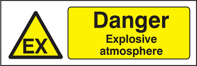 Atmospheres Regulations 2002 covers the regulations that should be followed for onshore installations.
For offshore applications, the Offshore Correct Selection & Use Of Equipment Electricity at Work : Safe Working Practices Page 8 of 33 Health & Safety Executive Installations (Prevention of Fire and Explosion, and Emergency Response) Regulations 1995 should be followed.
7. Partial Discharge & High Voltage Cable Breakdown

Partial Discharge Damage To Electrical Cable Insulation. Image HVPD
A Partial Discharge (PD) is an electrical discharge or spark that bridges a small portion of the insulation between two conducting electrodes.

Partial discharge is an electrical discharge or spark that bridges a small portion of the insulation between two conducting electrodes.
PD can occur at any point in the insulation system, where the electric field strength exceeds the breakdown strength of that portion of the insulating material.
Electrical failures of three phase HV switchgear are most likely to occur during, or shortly after, switchgear operation. The way switchgear is operated, its condition and the conditions in the electrical system at the time it operates will largely determine whether it will function safely.
The use of handheld partial discharge equipment can be considered for use as an additional safety measure during a routine inspection or when entering a substation. The use of partial discharge detection equipment can reduce the risks to people who perform inspections by providing a warning that something may be wrong.
HV electrical switchgear should not be used where its strength and capability may be exceeded unless there is no potential danger of anybody being exposed to the results. In order to prevent any future danger, switchgear and machines must be adequately maintained and details for guidance on the maintenance of HV electrical switchgear can be found in BS6626.
BS6626 is a British Standard which gives recommendations and guidance for the maintenance of electrical switchgear and controlgear having a rated a.c. or d.c. voltage above 1kV and up to and including 36kV.
Older switchgear may contain parts that were manufactured from asbestos or asbestos-containing materials (ACMs).
Read more: Video Tutorial Masterclass – PD Partial Discharge & Electrical Cable Breakdown
8. Electrical Equipment – Correct Selection & Use
Getting it right first time. When electrical installations are commissioned and installed, the correct equipment must be used to not only prevent electrical explosions and arc flash but to also minimise the financial costs associated.
If any old equipment is still in use including old type switchboards and fuse-boards used by electricity distributors, then this is not designed to prevent people touching live conductors and suffering injuries from shock or burns.
Electrical equipment to be used in hazardous areas must be certified for use and have adequate certification.
Consideration must also be given to the environment in which the equipment is being used and whether there is any potential for an explosion or leak to occur.
Potentially explosive atmospheres are regulated under the ATEX Directive in Europe and geo-specific hazardous area classifications cover the rest of the world. Adverse external factors should be considered for the electrical equipment such as excess damp or humidity conditions.
The assessment of the working area must be carried out before work commences – given average travel distance from an oil rig to the nearest hospital (by helicopter) offshore locations consequently have extremely rigorous electrical safety working practises. We covered BP’s recently….
Read more: ATEX Solenoid Valves – ASCO Valves for International Hazardous Area Installations
9. Assessing Safe Working Practices
Assessing safe working electrical practices can be divided into four stages :
- Deciding whether to work live or dead
- Planning and preparations for actions that are common to both dead and live working
- Procedures for working dead
- Procedures for working live
This basic flow chart for assessing safe working practices helps to assess exactly what should be taken into consideration:

Selection chart for assessing safe working practices
The age of switchgear and other electronic equipment should be taken into account as the risk of catastrophic failure increases with age and a process of assessment should be carried out to decide on the appropriate action for dealing with aged switch-gear.
10. Should You Work Dead Or Live?
Working either live or dead is dependent upon the work being carried out and the equipment being worked upon. Working dead simply means working on or with electrical equipment of which the power source has been switched off. Working live means the opposite – the power is still on and the equipment is live.
Typically, normal policy is to work dead and deciding whether to work dead or live is extremely important. It is normal for utilities to recommend work on or near electrical apparatus to be on de-energised equipment, not live, i.e. isolated.
There are a series of questions and points to consider when deciding between working and working dead live:
- Can the normal policy of dead working be carried out?
- There are three conditions that must be met for live working to be considered acceptable over dead working. These are: It is unreasonable in all the circumstances for the conductor to be dead? It is reasonable in all the circumstances for the person to be at work on or near that conductor while it is live; and suitable precautions (including, where necessary, the provision of personal protective equipment) have been taken to prevent injury.
- Is it unreasonable for the work to be done dead?
- There are some circumstances in which it would be unreasonable to make the equipment dead due to the difficulties it would cause. Situations where it may not be technically feasible, a DNO needs to connect a new low-voltage service to an existing main or switching off a system, such as the supply to an electric railway track would cause excessive financial cost.
- Identify, assess and evaluate the risks and methods for controlling them
- If it has been decided that the work must be carried out live, then a risk assessment is required to evaluate the work on or near the specific equipment and it must be carried out by someone with comprehensive knowledge and experience of the type of work.
- Decide whether it is reasonable to work live
- The risk assessment should inform managers and supervisors whether it is safe to work live. At this stage the operational and economic factors of the work being live should be taken into consideration and evaluated against the risks of working live.
- Decide whether suitable precautions can be taken to prevent injury
- Providing the required points have been met, live work can still only be justified if suitable precautions are taken to prevent serious injury arising from the hazards noted in the risk assessment.
Arc Flash – HV Substation Switching
Thorne & Derrick are global distributors for the full range of CATU electrical safety products.
The range that ensures your worker safety and prevents and injury or serious harm occurring.
Catu Electrical Safety Blog
- CATU Dexteri+ Electrical Insulating Gloves For Electrical Engineers, Linesmen & Cable Jointers
- 11kV-33kV Voltage Detection Using CATU CC765-10/36 For Substations, Cables & Overhead Lines
- CATU Electrical Safety Life Saving Kits For Offshore Oil & Gas Substations
- CATU CZ-54-RM Life Saving Kits For High Voltage Substations
THORNE & DERRICK SPECIALIST ELECTRICAL DISTRIBUTOR
LV ♦ MV ♦ HV
T&D distribute the most extensive range of LV, MV & HV Cable Jointing, Terminating, Pulling & Installation Equipment – we service UK and international clients working on underground cables, overhead lines, substations and electrical construction at LV, 11kV, 33kV and EHV transmission and distribution voltages.
- Key Products: MV-HV Cable Joints & Terminations, Cable Cleats, Duct Seals, Cable Transits, Underground Cable Protection, Cable Jointing Tools, Feeder Pillars, Cable Ducting, Earthing & Lightning Protection, Electrical Safety, Cable Glands, Arc Flash Protection & Fusegear.
- Distributors for: 3M, ABB, Alroc, Band-It, Catu, Cembre, Centriforce, CMP, Elastimold, Ellis Patents, Emtelle, Furse, Lucy Zodion, Nexans Euromold, Pfisterer, Polypipe, Prysmian, Roxtec.

LV – Low Voltage Cable Joints, Glands, Cleats, Lugs & Accessories (1000 Volts)

MV HV – Medium & High Voltage Cable Joints, Terminations & Connectors (11kV 33kV EHV)
Cable Laying – Underground Cable Covers, Ducting, Seals & Cable Pulling Equipment
T&D, CATU Electrical Safety & Arc Flash Protection Specialists for SAP’s, Linesmen, Jointers & Electrical Engineers – Largest UK Stockist
INVITATION
Thorne & Derrick invite you to join LinkedIn’s largest LV-HV Electrical Discussion Group : Low & High Voltage Power, Cabling, Jointing & Electricals. Discussion subjects include cable installations, cable jointing, substation, overhead line and electrical construction at LV, 11kV, 33kV and EHV. Network, engage and promote your profile, company or products with over 10,000 influencers.


OCS Group – Hazardous Area & High Voltage Commissioning, Inspection & Training Services
November 8th, 2017
by Chris Dodds T&D - estimated reading time 5 minutes
Headquartered in the USA, OCS Group is one of the largest independent inspection company’s, developing many proprietary services and products over the last 20 years for all their clients within the oil, gas, energy and hazardous area industries.
OCS Group works in collaboration with the regulators, government agencies and leading industry bodies for electrical safety in the work place to provide the best training available in the USA in respect to hazardous areas and high voltage power systems.
It is acknowledged that OCS Group is the industries leading expert in electrical safety and this has resulted in a growing relationship and ongoing collaboration with UL to provide the best of industry related competency based training. In addition, OCS is the leading training provider to drilling contractors and operators working in hazardous area and on high voltage systems in their region.
With offices in the USA, Singapore, Australia, Indonesia, Malaysia, Saudi Arabia, UAE and India, OCS Group provides a wide range of services to international oil and gas industries and other industrial engineering and energy markets.

OCS GROUP – Life Cycle of Services
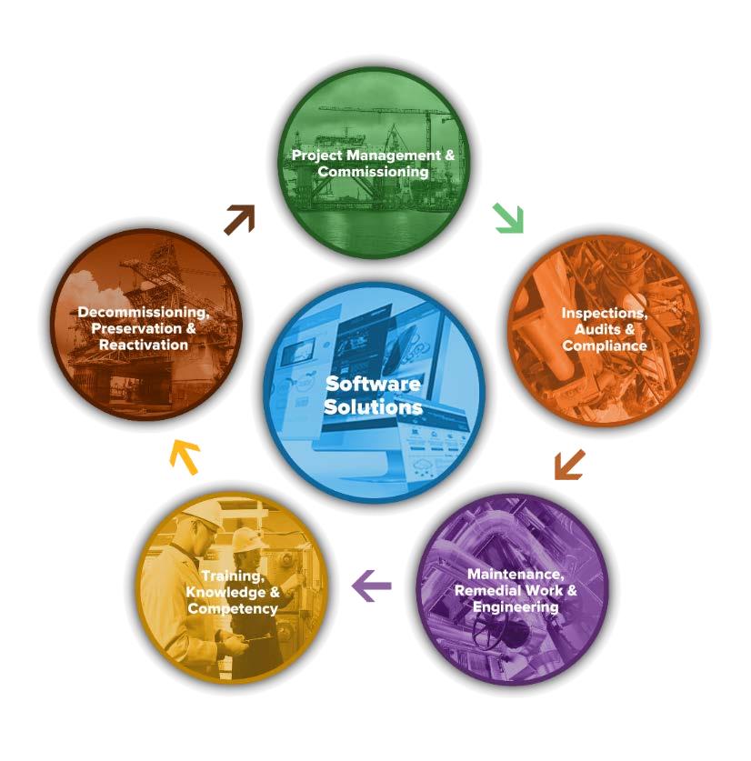
OCS Group delivers these services with an unwavering commitment to the highest safety and quality standards, evidenced by IS0 9001:2015 certification.
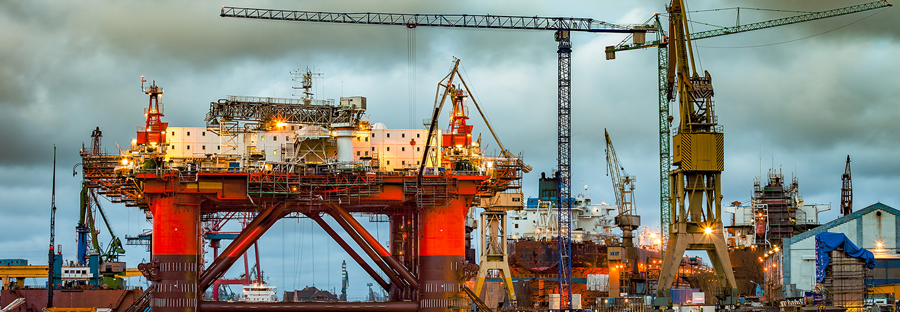
Project Management & Commissioning
OCS has global experience of over 150 successful hazardous area and high voltage project management, engineering, testing and acceptance projects delivered on time and budget.
All projects are managed through proprietary software developed in house specifically for land assets, jack-ups, platforms, FPSO’s, drill ships and refineries.
Inspections, Audits & Compliance
OCS Group over 20 years has built strong relationships with operators and contractors providing solutions for all types of hazardous area and high voltage inspections, audits and compliance surveys.
- Rig Inspections
- Hazardous Area
- DROPS
- NDT
- MCT
- Valuation
- Rope Access
- Competency Audits

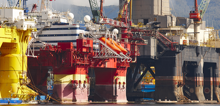
Preservation & Reactivation
OCS Group provides VCI materials, experienced and qualified personnel for application and preservation management for large and small projects. For 20 years OCS Group has been providing rig and asset re-activation services, continuously proving the process by ensuring your asset is ready to operate.
Software Solutions
- Hazard Trac: Hazardous Area Strategy and Management Software
- Drops Trac: Managing Drops on an asset, regional or global scale.
- Project Trac: Managing complex asset builds ensuring project delivery
- Inspection Trac: Tracking routine inspections and corrective action closeouts
- MCT Trac: Managing and Maintaining the required MCT register

Training & Competency
- CompEx Scheme: 01-04
- CompEx Mechanical
- Marine High Voltage (STCW-USCG)
- Hazardous Areas HAET – IADC
- Electrical for Industrial Applications
- Electrical for Renewable Applications
- Customized Training Programs
- Online Training
High Voltage
Houston based OCS Group has been awarded the United States Coast Guard (USCG) Marine High Voltage Safety accreditation as a Marine High Voltage Training Provider.
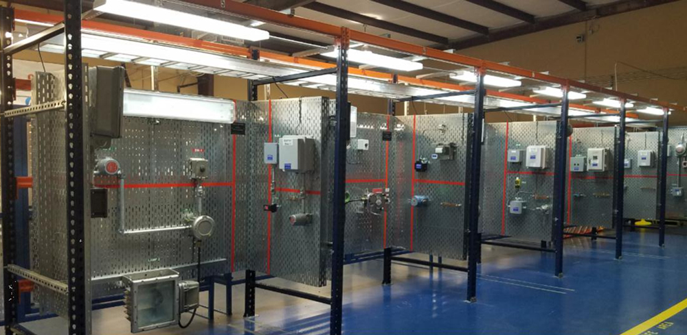
Hazardous Area Electrical (Ex) Management
OCS Group is a leading hazardous area (Ex) equipment Inspection Company, evidenced by their loyal clientele comprised of renowned, international drilling companies.
OCS Group follows IEC and NEC standards, employing CompEx certified inspectors to work on every Ex hazardous area inspection. Additionally, the technical training of staff ensures the professionalism of the entire inspection crew and operations personnel have the specialised knowledge and skills necessary to comprehensively complete the job with utmost client satisfaction.
The hazardous area management plan includes creating a register of every item within the Ex location. The equipment is inventoried, logged, inspected, tagged and verified for compliance. The end result is a detailed report outlining the remedial tasks required to make the hazardous area zone safe.
The Hazardous Area Electrical Register (HAER) Inspection consists of several Phases to choose from. Client Preparation required is an up to date area drawings and to provide all hazardous area equipment certification and maintenance system records for review.
- Phase One is a detailed inspection of all Ex equipment located in the identified ‘Hazardous Area Locations’ (or Zones)
- Phase Two is a separate scope of work of remedial task management to correct the deficient items identified in Phase One
- Phase Three is optional and can consist of a specific scope of work such as an Emergency Shutdown Devices (ESD), or a competency assessment of the assets’ workforce in a live simulation of an electrical Safe Work Practices
(SWP) audit
OCS Group – Solutions For Success
THORNE & DERRICK are national distributors of LV, MV & HV Cable Installation, Jointing, Substation & Electrical Equipment – we service UK and global businesses involved in cable installations, cable jointing, substation, overhead line and electrical construction at LV, 11kV, 33kV and EHV.
Since 1985, T&D have established an international reputation based on SERVICE | INTEGRITY | TRUST.
Contact us for 3M Electrical, ABB, Alroc, AN Wallis, CATU Electrical, Cembre, Centriforce, CMP, CSD, Elastimold, Ellis Patents, Emtelle, Euromold, Filoform, Furse, Lucy Electric & Zodion, Nexans, Pfisterer, Polypipe, Prysmian, Roxtec, Sicame, WT Henley.

Invitation
Thorne & Derrick invite you to join LinkedIn’s largest LV-HV Electrical Discussion Group : Low & High Voltage Power, Cabling, Jointing & Electricals.
Discussion subjects include cable installations, cable jointing, substation, overhead line and electrical construction at LV, 11kV, 33kV and EHV. Network, engage and promote your profile, company or products with over 10,000 influencers.


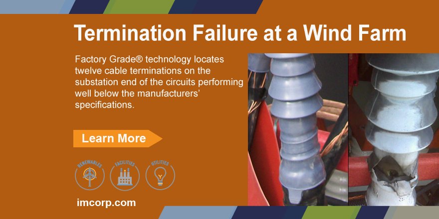
MV Heat Shrink Cable Terminations Can Fail Despite Passing VLF Tests
November 8th, 2017
IMCORP – Providers of Factory Grade® technology, bringing MV HV power cable and accessory manufacturers’ QC reliability to field installations worldwide.
by Chris Dodds T&D - estimated reading time 5 minutes
OVERVIEW
0.1 Hz VLF test and IMCORP’s Factory Grade® technology are compared side-by-side at utility solar site
CHALLENGE
VLF test passes cables, but cable terminations were still failing
RESULTS
Based on distribution system experience, utility uses IMCORP’s Factory Grade® technology to identify workmanship defects and VLF test induced damage
A utility client of IMCORP asked them to commission medium voltage cable systems at a new generation facility after experiencing several MV 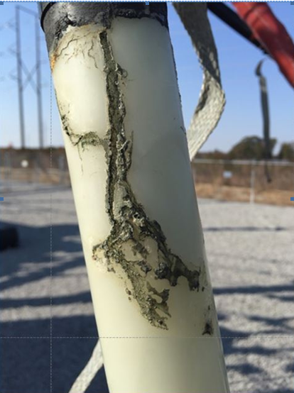 cable termination failures.
The cable installation contractor had already tested the MV cable systems with a very low frequency (VLF) test.
Uninformed contractors often make a claim based on a common myth that ‘proper’ VLF testing would detect serious MV-HV cable defects while not harming healthy cable insulation or aggravating minor defects.
In addition, the misguided claim often states that passing a VLF test means the medium or high voltage cable system will deliver years of trouble free service.
Wrong.
Unfortunately the owner initially believed these commonly held myths, energised the MV power system and subsequently experienced several catastrophic failures that damaged switchgear, costing them significant down time and losses in generation revenue.
Substandard MV HV cable jointing and installation necessitated the replacement of multiple HV heat shrink cable terminations after a succession of in-service cable termination failures.
Pictured opposite the heat shrink anti-track tubing has been removed shown the tracking between the medium voltage heat shrink and XLPE cable insulation.
The IMCORP Factory Grade® technology pinpointed dozens of MV cable terminations that did not meet the accessory manufacturer’s minimum performance standards.
When the cable terminations were dissected the technician not only found cable jointer workmanship issues, including insufficient shrinkage of heat shrink layers, but clear evidence of damage caused by the VLF test that passed the medium voltage cable terminations a short time before.
Ben Lanz (Director, Applications Engineering at IMCORP) comments, “a VLF test passed this heat shrink termination. An offline 1.5Uo 50/60Hz PD partial discharge assessment with 5pC sensitivity identified this MV cable termination which is why we have the picture. The original installation defect and VLF test damage are plainly visible. This case along with many others is the reason IMCORP recommend a factory comparable PD test for critical medium/high voltage power installations and QC spot checks for newly trained cable jointers and installers of MV-HV joints, terminations and connectors. I acknowledge that a VLF test was the best the utility and power industry had 10 years ago but with the evidence we have now, I generally don’t recommend going over the operating voltage with a VLF test since it can not find most MV-HV cable detects found by a factory comparable PD test.”
The 2 most serious cable termination anomalies were small voids on the medium voltage XLPE cable insulation shield interface and “fall-in” cable insulation problem at the conductor shield interface.
Could a failure to remove the semicon screen from the XLPE insulation of MV-HV cables contribute to this type of cable failure?
Here, the semicon screen was removed sufficiently from the MV-HV cable using correct cable jointing tools. Most likely the VLF test burned a track in voids caused by insufficient void filling mastic at the semicon cutback and/or insufficient shrinking of the heat shrink tube with the green zinc oxide (ZnO) stress controlling layer on the inside of the cable termination.
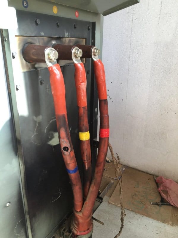
MV Cable Termination Failures
Here, failure of the heat shrink stress control component of the cable termination was poorly placed in relation to the semi-conductor screen cut causing termination failure of the substation cables linked to a generation plant on an onshore windfarm.
Manufacturers Standards
| Component Standard | Testing Frequency | Sensitivity | Voltage |
| Cable Terminations IEEE 48 | 50/60 Hz | 5pC | < 1.5 Uo |
| Cable Joints IEEE 404 | 50/60 Hz | 5pC | < 1.5 Uo |
| Separable Connectors IEEE 386 | 50/60 Hz | 5pC | < 1.3 Uo |
| MV Extruded Cable ICEA S-97/94-682/649 | 50/60 Hz | 5pC | < 4.0 Uo |
| HV EHV Extruded Cable ICEA S-108-720 | 50/60 Hz | 5pC | < 2.0 Uo |
Reducing Cable Termination Failures
Of course site standards and international working procedures vary but the following professional advice has universal methodology:
“There are three main components to reducing the risk of failure during the infant mortality phase of an installation’s life (bathtub curve): 1) Have policies that ensure you only procure high quality equipment 2) Ensure that equipment is installed by qualified, trained and experienced personnel who work to high standards 3) Commission it thoroughly with a view to exposing flaws and weaknesses and then correcting them. As has been proven many times before, thousands saved today may cost you millions tomorrow.”
Jason St Martin (Senior Electrical Inspector at DMIRS Building and Energy State of Western Australia)
Thorne & Derrick International
Cable Installation, Jointing, Substation & Electrical Equipment Distributors
Since 1985 T&D have serviced UK and international businesses involved in cable installations, earthing, duct sealing, jointing, substation, overhead line and electrical construction at LV, MV & HV.
Our customers are contractors, specifiers and end-users involved in cable installations, cable jointing, substation, overhead line and electrical construction at LV, MV & HV.
Medium voltage power cables can fail for several reasons – pictured below is a common installation error near the outer semicon screen cutback by the cable jointer on the heat shrink cable termination – the highest electrical stress point in an open air cable termination.
To prevent this IMCORP recommend MV HV Jointer Training coupled with a factory comparable partial discharge test after installation to provide feedback to the cable installer – 50/60Hz offline PD test with better than 5pC sensitivity.
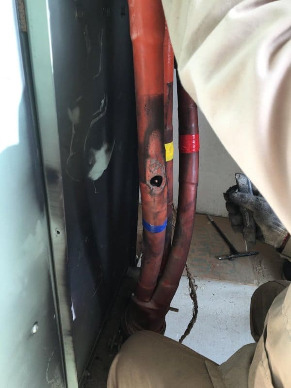
Partial Discharge (PD) at the crossed cores of the HV cable causing failure of the heat shrink cable termination
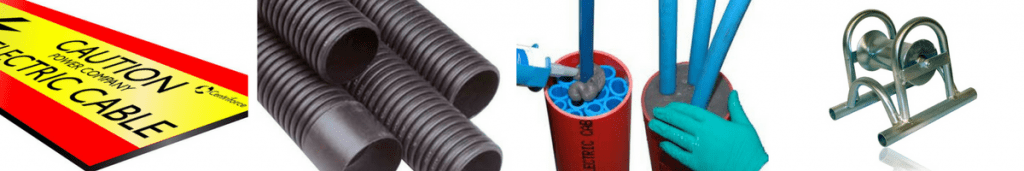
NPG Northern Power Grid Cable Protection & Tapes & Covers (LV MV HV)
November 7th, 2017
NPG LV MV HV 11kV 33kV | Tile Tape | Stokbord Covers
Northern PowerGrid Tile Tape & Stokbord Covers
Northern Powergrid, NPG, are a UK Distribution Network Operator distributing low and high voltage electricity covering North East England, – we overview current NPG recommendations and specifications for Cable Protection Tapes & Covers using Tile Tape and Stokbord products.
This should assist LV-HV Cable Jointing, Installation & Civil Engineering Contractors installing the appropriate level of LV-HV Cable Protection for underground power cables.
T&D are Approved Vendors to NPG and their contractors providing competitive prices and technical support for LV, MV & HV Cable Installation, Jointing, Substation & Electrical Equipment.
Trenchless Excavation
Where appropriate, trenchless excavation shall be considered as a viable option when installing underground cable. Application of this option shall always employ the cable being laid in a suitable and approved duct as shown below.
| Trenchless Installation Duct Requirements | ||
| Cable Type | Cable Size | Duct (Outside Diameter) |
| Metallic Auxiliary | All | 125mm PE SDR-11 Black |
| Fibre Auxiliary | All | 125mm PE SDR-11 Black |
| Fibre Auxiliary (Sub-Duct) | All | 32mm PE SDR-11 Black |
| LV Service | All | 75mm PE SDR-11 Black |
| LV Main | All | 125mm PE SDR-11 Black |
| 11kV to 20kV | Triplex up to 300sqmm | 125mm PE SDR-11 Black |
| Triplex above 300sqmm | 160mm PE SDR-11 Black | |
| 33kV | Single Core | 160mm PE SDR-11 Black |
| Triplex up to 400sqmm | 160mm PE SDR-11 Black | |
| 66kV to 132kV | All | 180mm PE SDR-11 Black |
All ducting used in trenchless excavation shall be solid wall circular section duct (SDR-11) as specified in ENA-TS 12-24 – ‘Plastic Ducts for Buried Electric Cables 2008’and NPS/002/003 – ‘Technical Specification for Protective Tile, Tile Tape and Cable Ducting’ and all cables require advanced warning and this will normally be in the form of an embossed black duct compliant with ENA-TS 12-24 – ’Plastic Ducts for Buried Electric Cables 2008’.
Open Cut Trench
| Open Cut Trench Installation Requirements | |||||
| Cable Type | Cable Size | Public Footpath (OD / ID mm) | Private Domestic (OD / ID mm) | Private Non-Domestic (OD / ID mm) | Road (OD / ID mm) |
| Metallic Auxiliary | All | 96.5/90 Duct & Tile Tape | 96.5/90 Duct & Tile Tape | 96.5/90 Duct & Tile Tape | 96.5/90 Duct & Tile Tape |
| Fibre Optic Auxiliary | All | 96.5/90 Duct & Tile Tape | 96.5/90 Duct & Tile Tape | 96.5/90 Duct & Tile Tape | 96.5/90 Duct & Tile Tape |
| LV Service | All | Laid Direct & Tile Tape | 38/34 or 46 Duct & Tile Tape | Laid Direct & Tile Tape | 150/125 Duct* & Tile Tape |
| LV Main | All | Laid Direct & Tile Tape | 150/125 Duct* & Tile Tape | Laid Direct & Tile Tape | 150/125 Duct* & Tile Tape |
| 11kV to 20kV | Up to 300sqmm | Laid Direct & Tile Tape | 175/150 Duct* & Tile Tape | Laid Direct & Tile Tape | 150/125 Duct* & Tile Tape |
| Above 300sqmm | Laid Direct & Tile Tape | 175/150 Duct* & Tile Tape | Laid Direct & Tile Tape | 175/150 Duct* & Tile Tape | |
| 33kV | Triplex up to 400sqmm | 160/150 Duct & Tile Board | 160/150 Duct & Tile Board | 160/150 Duct & Tile Board | 160/150 Duct & Tile Board |
| All Single Core | 160/150 Duct & Tile Board | 160/150 Duct & Tile Board | 160/150 Duct & Tile Board | 160/150 Duct & Tile Board | |
| 66kV to 132kV | All Single Core | 160/50 Duct & Tile Board | 160/150 Duct & Tile Board | 160/150 Duct & Tile Board | 160/150 Duct & Tile Board |
*Assumes twin wall ducting. All others are single smooth wall design.
All sizes for ducts installed in open trenches are nominal diameter measurement and should have tile tape or tile board installed above the cables / ducts ensuring an overlap of 50mm either side of the cable(s)/duct(s).
Cables in the range 230V to 20kV shall be laid under tile tape positioned 150mm directly above the top of the uppermost cable / duct and 33kV to 132kV shall be laid under tile boards positioned 75mm directly above the top of the uppermost cable / duct with each tile board shall be closely interlocked with adjacent covers throughout the length of the cable.
All ducting used in open trench excavation shall be used as part of cable installation works shall be as specified in NPS/002/003 – ‘Technical Specification for Protective Tile, Tile Tape and Cable Ducting’.
Cables installed for future jointing to existing cables shall be adequately overlapped to allow easier jointing.
➡ View our complete range of LV-HV Cable Protection.
Cable Pulling & Laying Equipment LV HV
T&D supply Utilities & Approved Contractors with cable pulling products including cable rollers, cable socks and drum lifting jacks to enable the installation of low voltage and high voltage cables intro trench or duct: this includes single core, 3 core and Triplex 11kV/33kV power cables and LV waveform, mains and service cables.
Cutting 11kV Cables Using Cembre Battery Cable Cutting Tools
October 23rd, 2017
by Chris Dodds T&D - estimated reading time 5 minutes
Product Category: Cable Cutting Tools
Featured Manufacturer: Cembre
Cable Cutting Tool Model: Cembre B-TC950 Cordless Hydraulic Cutting Tool
Contributed By: Watkins and Jacomb Construction Power & Consultancy
WJCPC are specialist LV HV Cable Jointing contractors with over 20 years experience in the electrical industry covering the utilities, renewable energy, rail, data centre and general industry sectors – with UKPN competency for LV HV Jointing, Confined Spaces, Substation Entry and Fault Finding.
The video below shows WJCPC cutting a section of BS6622 11kV 3 core medium voltage power cable using the battery operated Cembre B-TC950 tool prior to terminating into the MV cable box using heat shrink terminations.
The Cembre B-TC950 battery operated cable cutting tool has a capacity to cut up to 95mm outside diameter power cables including 11kV and 33kV. The Cembre tool features a dual speed cutting action – the two speed operation and automatic switching from a rapid advancing speed of the ram to a slower, more powerful speed for cutting copper and aluminium conductors.
Not suitable for cutting steel wire armour (SWA) or live/energised cables.
Cembre B-TC950 has a cutting power of 880 bar (12,700 psi).
How To Use Cembre Cutting Tools
Cutting Blade Advancement
The user or jointer should press the operating button (5) to activate the motor-pump – the ram will gradually move forward until the lower cable cutting blade (3) touches the cable conductor. To halt the advancement of the tool blade, release the button (5) and the motor will cut out. Ensure the cutting blade is exactly positioned on the desired cutting point of the cable – if not re-open the blade following instructions and reposition it.
Cable Cutting
Firmly hold the Cembre tool and operate the button (5) to gradually move the lower cutting blade (4) to cut through the conductor. When the conductor cut is clean and complete, release the button (5), otherwise the maximum pressure relief valve has activated.
Blade Retraction
By operating the pressure release button (6), the ram will retract and open the lower cutter blade of the tool.

Cembre B-TC950 Cable Cutting Tools – Distributed by T&D
Cembre B-TC950 Battery Operated Hydraulic Cable Cutting Tool
Construction & Spare Parts

Dimensions 518 x 468 x 83 (20.4 x 18.4 x 3.3).
- Locking Lever
- Upper Cutting Blade
- Lower Cutting Blade
- Tool Handle Grip
- Operating Button
- Pressure Release Button
- Battery
- Battery Capacity Indicator
- Battery Checkbutton
- Battery Release
- LED Worklight
- Ring For Shoulder Strap
T&D distribute a complete range of cable cutters including ratchet, hydraulic and battery operated for precise and clean cutting of power, control and instrumentation cables with steel wire armour or braid and lead covered sheathings – ratchet cable cutters are recommended for cropping cable conductors of LV-HV cables where working space and access is confined in high voltage cable end termination boxes.
11kV Cable Preparation
Training & Tools
Failure to effectively and precisely prepare MV-HV cables by the jointer is a common cause of 11kV cable failure – images 1+2 below are clear examples of jointers workmanship deficiencies on a recent project which WJCPC were contracted to correct and complete following the condemning of the 11kV cable installation by the main contractor.
The 11kV 3 core XLPE medium voltage power cables show a reckless finish to the easy peel semiconductor screen with a toxic mixture of jagged edges, scoring marks and deep ringing – this could have been caused by the jointers using fully bonded screen removal tools with incorrect depth setting rather than the correct semicon stripping tool. The use of the correct cable jointing tools for each stage of cable preparation is critical to ensure safe and reliable installation and service of MV joints and terminations.
Compare images 1+2 with the perfect uniformity of MV cable preparation in image 3 achieved by WJCPC.
Critical to the long term stability and field performance of 11kV cable terminations and joints is perfect preparation of cable – care should be taken to ensure appointed MV HV Cable Jointing contractors are suitably trained and equipped with the required jointing, cutting and crimping tooling to perform medium/high voltage cable installations.

THORNE & DERRICK are national distributors of LV, MV & HV Arc Flash Clothing, Cable Installation, Jointing, Substation Duct Seals & Electrical Equipment – we service UK and global businesses involved in cable installations, cable jointing, earthing substations, overhead line and electrical construction at LV, 11kV, 33kV and EHV.
Since 1985, T&D have established an international reputation based on SERVICE | INTEGRITY | TRUST.
Contact us for 3M Electrical, ABB, Alroc, AN Wallis, CATU Electrical, Cembre, Centriforce, CMP, CSD, Elastimold, Ellis Patents, Emtelle, Euromold, Filoform , Furse, Lucy Electric & Zodion, Nexans, Pfisterer, Polypipe, Prysmian, Roxtec, Sicame, WT Henley.
