

Cable Cleats
Cable Hangers for the Support & Management of Cables
March 17th, 2022
Ellis Patents | Cable Hangers & Cleats Supplied in the UK by Thorne & Derrick
Cable Hangers & Support
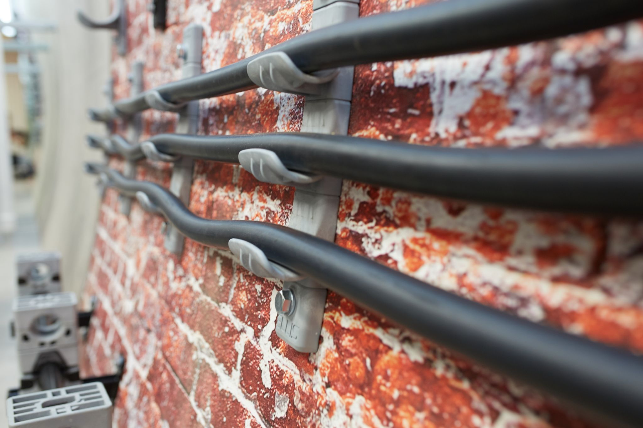
Pegasus is a modular cable hanger system that is stronger, lighter and, because it is has been designed to be made to order, incredibly flexible in comparison to traditional J-type galvanised steel cable hanger systems.
Pegasus from Ellis Patents comprises a non-corrosive marine grade, extruded aluminium spine that supports any number and combination of plastic cable hangers that are manufactured from a high strength nylon especially formulated to meet the requirements of the London Underground 1-085 specification.
Pegasus Benefits for Hanging Cables
– Corrosion free nature as a result of there being no bimetallic contact and the aluminium spine being fully enclosed to protect the hanger system against the corrosive effects of brake dust.
– Curved saddle shape on all cable hangers that prevents cable damage caused by sharp edge contact with the outer sheath or jacket of the supported cables.
– Modular design that allows assembly with any number of hangers in any combination, giving designers the ability to produce the cable layout they want.
Manufactured by Ellis Patents, the global market-leader in the manufacture of cable cleats for the management and support of LV MV HV cables.

February Rail Project | Working with Ellis Patents we completed the specification and have now moved into manufacturing for our largest contract to date to supply TfL (London Underground) approved cable hangers across several depot modernisation projects.
Thorne & Derrick in consultation with the Asset Manager at Transport for London and their appointed Telecoms & Power contractor secured formal Authorisation & Approval for the Pegasus range of non-metallic cable support hangers.
The product will provide safe cable management of the cable route within the Bridges & Structures category – over 1000 hangers with proven lifecycle performance and utilising the standard J-type design for support of multiple cable runs including single, 3-way and 5-way configurations are now scheduled for delivery.
Associated Articles
- Cable Hangers for Railway Tunnels | Ellis Pegasus Cable Hangers
- Ellis Patents Pegasus Cable Hangers For Rail Cable Support
- Cable Cleats Help Tackle Copper Cable Theft on Railways
Rail Cable Accessories, Electrification
& Installation Equipment
Thorne & Derrick supply an extensive range of 400V-33kV Rail Cable Accessories & Power Distribution Sytems including feeder pillars to contractors undertaking Low Voltage Power Distribution, HV Electrification & Substations, DC Traction & Networks, OLE and Track Feeder Cable Renewals – a complete range of Network Rail PADS approved track terminations, cable joints, cable repair and connection products up to 25kV AC.
Full range of Cable Pulling Equipment & Products to ensure safe and efficient of rail cables in to cable ducts and containment infrastructure including cable troughs.

MITA GRP Cable Support Systems | Press Release
February 14th, 2022
MITA GRP Cable Support Systems
The below is a Press Release announcing that the MITA Brand are now empowered by Wibe Group.
We are MITA, and we are back.
As a matter of fact, we never left.
We have been supporting our customers through their technical journey on choosing the right product in cable support applications for almost five decades.
With our Mita GRP Cable Ladder, CABSYS Cable Tray, Troughing and Fibastrut ranges, we continue to lead the industry towards a sustainable future.
I am proud to share that as of the 1st of January 2022, we will be fully separated from Schneider Electric operationally and will have stand-alone presence in the UK with our “Made in UK” products which are fully compliant to the related cable management standards.
We cannot hide our enthusiasm having the legend, a 50 year young brand Mita, back on track in the UK market. We are grateful for Schneider Electric’s support so far.
We are now dedicated to bring the best-in-class products and services directly to you with the least time to market and highest competitive advantage. We have our focus on you and are ambitious to grow together.
Wibe Group
This stand-alone company, namely Wibe Group UK Ltd, is a part of Wibe Group. Wibe Group is headquartered in Sweden and is owned by Storskogen which is a publicly listed company founded in 2012, with a mission to acquire and operate well-managed and profitable companies with leading positions in their respective markets.
Wibe Group hosts four of the world’s leading cable management brands WibeR, StagoR, DefemR and MitaR. Looking ahead to the next century, we are reinventing ourselves. This new independent group company offers a complete, innovative range of cable ladders, cable cleats, cable trays and mesh trays for applications ranging from commercial buildings to extreme demanding industrial environments.
We see a bright future where we continue to create clever uplifting solutions together. We are here, stronger than ever.
Patrick Arcidiacono
CEO, WIBE Group UK Ltd and WIBE Group

RAIL CABLE ACCESSORIES, ELECTRIFICATION

& INSTALLATION EQUIPMENT
Thorne & Derrick supply an extensive range of 400V-33kV Rail Cable Accessories & Power Distribution Systems including feeder pillars to contractors undertaking Low Voltage Power Distribution, HV Electrification & Substations, DC Traction & Networks, OLE and Track Feeder Cable Renewals – a complete range of Network Rail PADS approved track terminations, cable joints, cable repair and connection products up to 25kV, including 3M Cold Shrink, Pfisterer CONNEX and Nexans Euromold products.
Full range of Cable Pulling Equipment & Products to ensure safe and efficient of rail cables in to cable ducts and containment infrastructure including cable troughs.
Cable Cleats | Cable Hangers | Cable Joints | Cable Glands | Cable Lugs | Cable Transits | Arc Flash Clothing
Cable Hangers for Railway Tunnels | Ellis Pegasus Cable Hangers
October 7th, 2021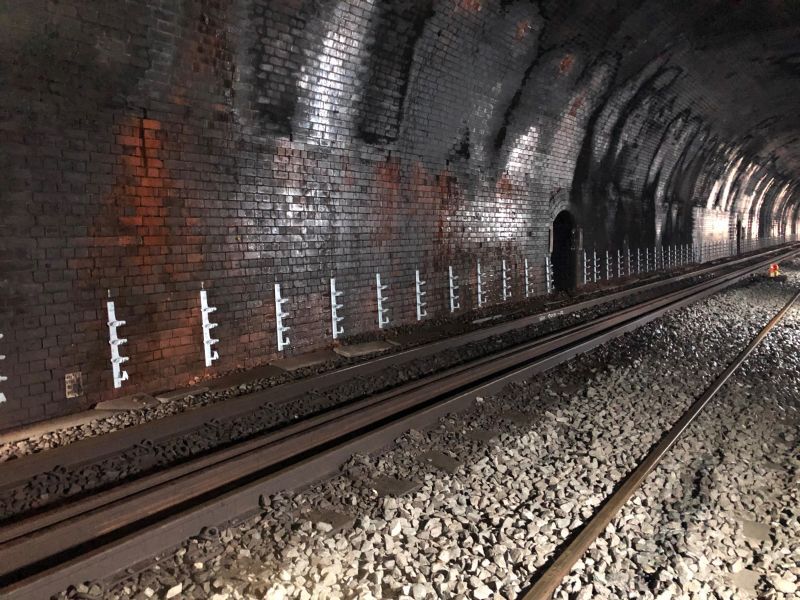 Pegasus Cable Hangers
Manufacturer of cable cleats and industry innovator, Ellis Patents has secured an order that has seen its Pegasus cable hangers hung at one metre intervals throughout the 1.6-mile length of one the world’s oldest railway tunnels.
The Summit Tunnel, which runs beneath the Pennines between Littleborough in Greater Manchester and Walsden near Todmorden in West Yorkshire, was constructed between 1838 and 1841.At the time of its opening, it was the longest railway tunnel in the world.
Ellis Patents’ Pegasus cable hangers were installed as part of a track renewal project being carried out in conjunction with Network Rail under the auspices of the Central Rail System Alliance (CRSA).

Ellis Pegasus | Non Metallic Cable Hangers
Kelly Brown, Ellis Patents’ Head of Sales, said: “The size of the railway structure in the UK is staggering. There’s over 20,000 miles of track, 30,000 bridges, tunnels and viaducts and many thousands of signals, level crossing and stations – and huge swathes of it date back to the 19th century.”
“With that in mind every product we design and manufacture for the rail industry is developed with longevity as well as ease of installation, maintenance and renewal very much to the fore.”
As with all its products, Pegasus was designed and developed completely in-house by Ellis Patents. Featuring an aluminium spine that can support any number and combination of plastic cable hangers, the modular cable hanging system is stronger and lighter than any other similar products – and because it’s been designed to be made to order it’s also the most flexible solution available.
“Traditionally cable hanging systems have been anything but convenient,” continued Kelly. “They have come in set sizes and configurations; have weighed so much they needed at least two people to install them; and because they have been manufactured from galvanised steel they are subject to corrosion. In contrast, Pegasus is light, but exceedingly strong, corrosion and fire resistant and has all the necessary rail industry approvals.”
Pegasus Non Metallic Cable Hangers
The cable hanger material is a high strength nylon especially formulated to meet the requirements of the London Underground 1-085 Specification.
Independent testing is carried out to prove conformance to the standard including toxicity, limited oxygen and smoke emission. The extruded aluminium spine is marine grade and its specially shaped profile has been designed to offer high strength rigidity.
Resistance to ‘self-corrosion’ and ‘bi-metallic corrosion’ are considered in the design and the non-metallic nature of the materials ensures that corrosion would not occur even in the harshest of environments.

Cable Hangers – Non Metallic Cable Hanging Systems (LV MV HV Cable) – Dimensions

LV, MV & HV Jointing, Earthing, Substation & Electrical Eqpt
Thorne & Derrick International are specialist distributors of LV, MV & HV Cable Installation, Jointing, Duct Sealing, Substation & Electrical Equipment – servicing UK and global businesses involved in cable installations, cable jointing, substation, overhead line and electrical construction at LV, 11kV, 33kV and EHV.
THORNE & DERRICK Product Categories: Duct Seals | Cable Cleats | Cable Glands | Electrical Safety | Arc Flash Protection | Cable Jointing Tools | Cable Pulling | Earthing | Feeder Pillars | Cable Joints LV | Joints & Terminations MV HV

WITHDRAWN IEC 61914:2009 | Cable Cleats for Electrical Installations
August 4th, 2021
By Chris Dodds | Sales & Marketing Manager at Thorne & Derrick International | Specialist Distributor for Ellis Patents | UK Leading Manufacturer of Cable Cleats for LV MV HV Power System Protection

The following article has been authored with the intent to highlight a serious specification shortcoming with respect to the understanding of conformance to the current IEC standard and the short-circuit testing and purchasing of cable cleats.
Working with Ellis Patents, Thorne & Derrick have successfully addressed this issue across several recent UK projects in the offshore wind, battery storage, utility substation and data centre sectors – needless to say, power is everywhere, and we hope this article will lead to a more widespread correction and update at specifier and contractor levels throughout the electrical industry.
Thorne & Derrick are a leading Specialist Distributor of LV HV Jointing, Earthing, Substation & Electrical Eqpt; this includes Cable Management, Fastening & Support Systems such as cable ties, cable hangers and strapping systems for LV up to 132kV power cable networks located onshore and offshore in industrial, hazardous and high voltage applications.
To nutshell this for us, you should ensure your cable cleats are tested to IEC61914:2015 – IEC61914:2009 is Revised, Superseded and Withdrawn. Here is why.
So What’s Changed?
IEC 61914:2009 Is Withdrawn
IEC 61914:2015 is available as IEC 61914:2015 RLV which contains the International Standard and its Redline Version, showing all changes of the technical content compared to the previous edition.
IEC 61914:2015 specifies requirements and tests for cable cleats and intermediate restraints used for securing cable in electrical installations. Cable cleats provide resistance to electromechanical forces where declared. This standard includes cable cleats that rely on a mounting surface specified by the manufacturer for axial and/or lateral retention of cables.
This 2nd Edition of IEC61914 cancels and replaces the first edition published in 2009. This edition constitutes a technical revision. This edition includes the following significant technical changes with respect to the previous edition:
a) Additional declaration and test for lateral load retention depending on cleat mounting orientation with associated new figures;
b) Additional declaration of the distance between the cable centres in any short-circuit test and associated new figures;
c) Specification of the cable to be used in short-circuit testing and relaxation of the ambient temperature limits for the test;
d) Additional requirement to photograph the short-circuit test arrangement before and after the test and to record more complete details of the cable used;
e) Revised parameters for the test of resistance to UV light.
This edition also includes the following editorial changes with respect to the previous edition:
f) Revised and updated normative references and bibliography;
g) Editorial clarification of definitions;
h) Editorial clarification of procedures for selection of test samples and the testing of cleats designed for more than one cable;
i) Relaxation of some mandrel material requirements;
j) Clarification of the inspection requirements following a short-circuit test and adding the option of either a.c. or d.c. voltage testing following a second short-circuit;
k) Clarification that the resistance to corrosion test applies to all types of fixing;
l) New cleat example illustration;
m) Limitations of use of the formulae in Annex B added.
“Cable cleats are critical electrical safety products – in the event of a short circuit they can protect your people, not just plant. During a recent tender bid we were alerted to non-conformance of a competitor product during the technical qualification procedure for a major UK infrastructure project. Simply, their product was tested to the cancelled 2009, not superseding 2015 version. Thorne & Derrick distribute LV HV Cable Accessories & Electrical Equipment from market-leading manufacturers tested to the current range of international standards,” comments Chris Dodds (Sales Manager at Thorne & Derrick).
“The closest example I can think of for this is car seat belts. If you were on the market to purchase a car and were advised that the seatbelts on the car you had chosen were not compliant to the latest industry standards, you may decide against purchasing that car due to safety concerns. Moreover the car would not be safe for sale in UK or European markets and would not bear the required UK CA or CE mark. Cable cleats for cables can be viewed in a similar way to seatbelts in cars as they both perform safety functions, adds Noman Shabir (National Sales Manager at Ellis Patents).


All cable cleats stocked and supplied by Thorne & Derrick are short-circuit tested to the current updated version IEC61914:2015.
The Trackside Conduit
July 6th, 2021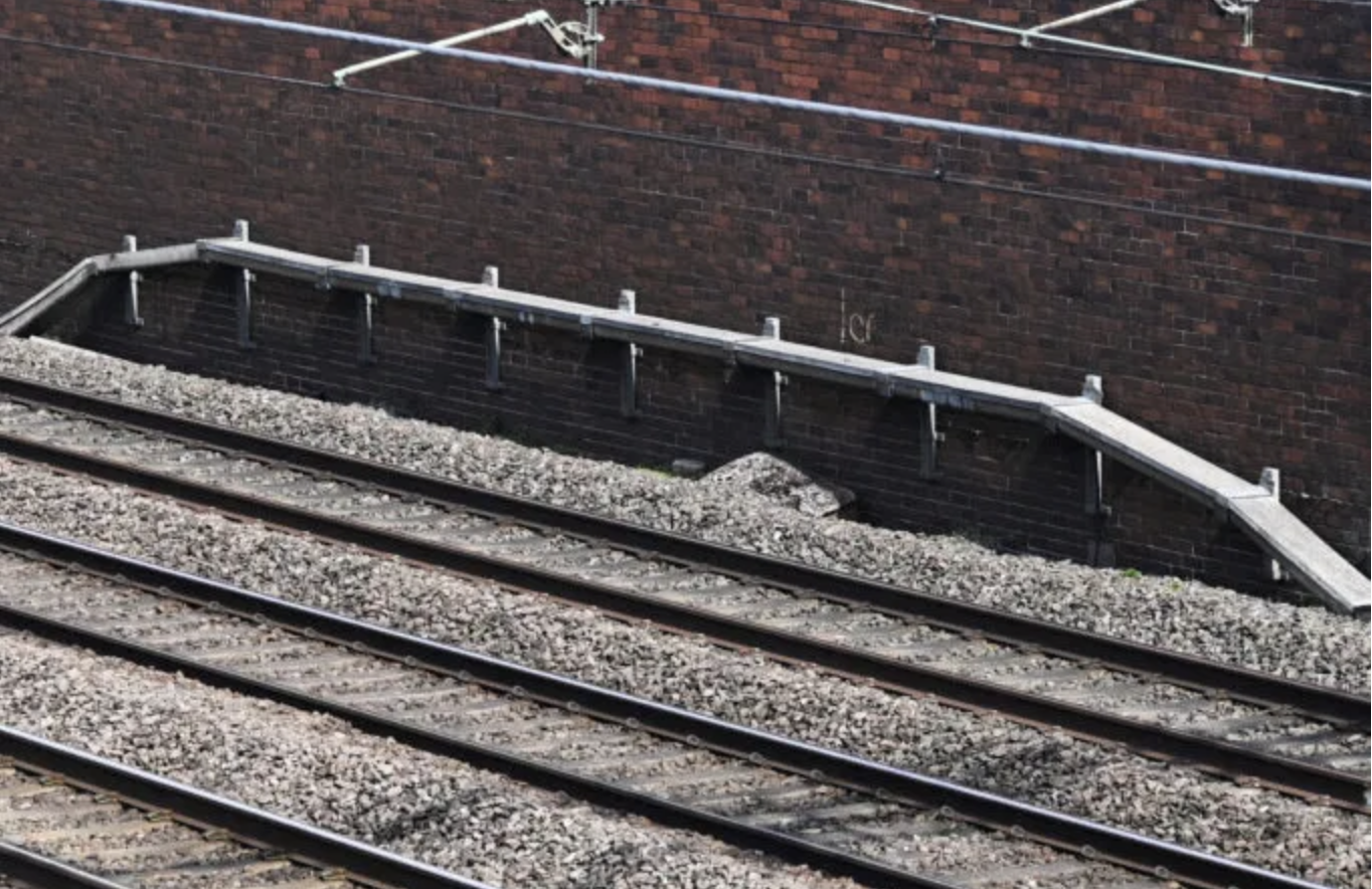
-
Special thanks to Paul Darlington from the Rail Engineer magazine for kind permission to republish this article
Data connectivity is vital for all aspects of society and industry, and is becoming increasingly important for railway operations. Signalling, electrification control, fixed and radio communications: all rely on cables running alongside the railway.
However, the integrity and value of these rail cables is only as good as the protection offered by the lineside cable route. Often overlooked or taken for granted, it is vital for the safe, efficient operation of any railway.
The primary function of any form of cable route is to protect the cables within.
Ideally it should provide mechanical protection, so it must be robust and stable, fire and vandal proof, capable of being opened and closed to maintain the cables or run new ones, be cost effective and safe to install, and require minimal maintenance.
Cable routes can be constructed from a variety of materials and come in different sizes and shapes. Transition modules may be required along with ‘T’ junctions, bends and joint bays.
All these requirements are not easy to achieve and can conflict. An assortment of route types have been used over the years and the search for an ideal cable route is never ending.
An evolutionary approach
The first types of cable routes were open copper wires raised on wooden poles. With the introduction of overhead electrification, signalling and telecoms cables were run at ground level in some form of cable containment. On the majority of non-electrified lines or those with conductor rails, cables are now provided at ground or sub-surface level.
Wooden cable routes were used initially, but these soon rotted and have not been used for many years. Asbestos cable routes mounted on posts were then provided, but these didn’t offer much mechanical protection and introduced a health and safety risk.
One of the more successful systems was concrete ground-level troughing, generally known as GLT. With detachable lids, this has been used for many years and is supplied in various sizes, generally in 1m lengths.
It provides reasonable mechanical strength, although the natural walkway it forms encourages its use as a lineside pathway. It was not designed for this purpose and a misaligned lid can easily cause injury if walked on.
The weight of concrete troughing gives it reasonable stability, but makes it difficult to handle manually and its installation can require extensive possessions for off-loading.
Deeper and higher ballast shoulders have, in places, transformed the troughing into ballast retaining walls or totally burying it. Any displaced alignment may put strain on the cables within and make it even more hazardous to walk on. While concrete troughing is reasonably inexpensive for the protection achieved, it is costly to install with manual labour and requires frequent replacement of damaged lids
In the 1960s, to obviate many of the disadvantages of the precast concrete route whilst retaining its inherent advantages, a continuous slip-formed concrete route was trialled. A train with an earth plough formed a trench alongside the track. Concrete was then discharged from the train into the trench, after which the train made a further pass with a plough to create a trough in the concrete. Once dry, precast concrete lids were off-loaded.
This method removed much of the manual labour involved in construction, but required a site with soil suitable for the earth plough, precise control of the concrete mix consistency, accurate rate of discharge into the trench and consistent train speed. It was also found that an unplanned thunderstorm turned a near-finished length of route into a disaster area! The trial was abandoned.
Buried cables
In areas of theft risk, cables can be buried directly in the ground at a depth providing adequate protection. Installation is generally required immediately after the trench has been dug as heavy rain can collapse it prior to backfilling. Alternatively, a duct system can be buried prior to the cables being pulled through or, in the case of fibre cables, blown through with compressed air.
Any buried route is expensive to install – particularly with manual labour – and may require rail-mounted machinery for excavation. Gaining access to the cables requires careful selection of the breakout point locations, together with jointing bays. The chosen cable must be suitable for direct burial and it is not easy to subsequently connect into the cable route.
Another method of direct burial is by utilising a rail or vehicle-mounted mole plough.
This is a hydraulically controlled plough blade, with the cables fed through trackside conduits in the blade.
In the right situation the method has some advantages, but large cables can present problems as certain types of soil do not consolidate and can leave a damaged embankment or cess. The method requires careful planning and preparation, with robust buried service checks prior to the cable-laying.
It only takes one old signal base to break the plough and seriously delay the programme. In locations with sharp stones, additional cable protection is required with sheathing or sand backfill. However, ploughing small fibre cable ducts could be an answer for the future. We’ll come back to that later.
Plastic routes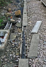
Over the years, various sorts of plastic cable routes have been trialled for lineside cable containment. Unfortunately, they have generally not provided the required mechanical strength, especially when faced with ballast alongside the route. Plastic also contracts and expands as the temperature varies and it is not easy to incorporate adequate expansion mechanisms.
Railtrack had some success installing a 100mm plastic surface pipe with thermal expansion mitigation which was staked into the ground every few metres. This provided protection to a telecoms cable running between signal boxes on rural routes and is still in use 25 years later. This wasn’t suitable for larger volumes of cables on main lines and it wasn’t easy to provide regular cable breakout points.
Recycled polymer
Over the last ten years, cable routes made from 100% recycled polymers – such as polypropylene – have been introduced which offer similar high strength and impact resistance to traditional concrete, but are approximately five times lighter for the same size and far easier to cut.
A further enhancement – building on the problem of walking on narrow concrete lids – was the introduction of a combined cable route and safe walkway, also made from recycled polymer. Two routes with the equivalent capacity of two concrete troughs were located under a 700mm wide non-slip surface. The lids were constructed so that cables could be laid with half the route open. Fixings were also provided for a removable handrail and the ability to secure the lids to the troughing to deter cable theft.
Following removal of the lids for installation purposes, there have been reports of a route’s sidewalls being deflected inwards due to the weight of the adjacent ballast, preventing the lids being replaced correctly.
This caused the lids’ outer edges to be unsupported and move unexpectedly under the weight of footfall, thus creating a trip hazard. This illustrates the need for maintenance of all cable routes and, in this case, to ensure the lids were securely attached to the sidewalls and not displaced from their correct positions.
Elevated troughing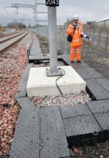
In cuttings susceptible to slippage, the toe cannot be excavated to accommodate a trough or buried route, so an elevated troughing route may be required, mounted on posts which only interfere with the soil formation at a minimal number of points. As well as early use of asbestos, elevated troughing has been constructed from a variety of materials over the years including timber, cement, glass-reinforced plastic, metal, recycled polymer and glass-fibre reinforced concrete (GRC).
Many elevated routes lose their alignment during their lifetime due to movement in the soil foundation and are particularly prone to damage as they form an obstruction to track work and make natural seats. Nevertheless, elevated GRC routes have, in particular, been widely used and are easy to transport and install.
Theft & vandalism
Vandalism and theft of copper cables have produced particular problems. Concrete routes may require lids to be fixed with metal clips or epoxy adhesive to deter theft.
In high-risk areas, cables have been sealed into GLT with concrete, but this is generally not recommended as cement can harm some cable sheath types and filling the trough route with concrete makes it unusable for other cables.
It is also expensive and labour intensive. Putting blobs of concrete in the trough is not good either as thieves have been known to cut and steal the intervening length, making it difficult to run a replacement cable.
Buried routes are quite effective as a deterrent if sufficient depth is maintained and the soil is well consolidated, although it has proved necessary in some locations to anchor the cables to prevent them being pulled from the ground using road vehicles.
Fibre cables – Trackside Conduit
When the national fixed telecoms network was deployed by Network Rail, a heavily armoured variant of the normal armoured optical fibre was chosen to deploy without any cable route. This was known as Double-Insulated Super Armoured Cable or DI-SAC which was approved for use where only optical fibre cables were required.
DI-SAC comprised 24 single-mode optical fibres divided equally into two stainless steel tubes, helically wound around a solid aluminium former, encased inside a medium-density polyethylene inner sheath and thick steel-wire armour, with a green over-sheath of fire-retardant ethylene vinyl acetate.
In walking areas and those prone to vandalism, DI-SAC was scratch-buried so it did not protrude above ground level. Nominally, it was secured into the ground every 40m, but this distance varied to prevent the DI-SAC being pulled onto the track. Its use without a cable route was questioned by many in the industry, but it saved the national fibre project several hundred million pounds. The cable was specially made in high volumes and is no longer commercially available.
Blown fibre
Fibre optic technology has now become the norm for telecoms transmission as it provides huge data transmission capability, solves the problem of inductive interference with long distance copper cables and has no theft value.
Fibre cables were traditionally installed in concrete trough routes in lengths of up to 2km. Selected fibres would be broken out to connect to the digital transmission equipment. Originally, such equipment would use local copper cable tails to provide connections to equipment such as telephones, data terminals, radio base stations and signalling interlockings.
With the introduction of all-IP (internet protocol) networks, fibre-borne digital signals right to the end device are now becoming the norm which has led to the concept of ‘blown fibre’ as an option.
This involves a composite material pipe incorporating several ducts of different sizes being installed either on the surface or buried. Bundles of fibres can then be blown into the duct using compressed air and further bundles can be similarly installed into different tubes at a later date, as required.
One drawback of normal routes is that new cables tend to be laid on top of existing cables in the route. When new signalling or telecom systems are brought into use, the redundant cabling remains in place and the trough becomes over-full. With fibre blowing it is relatively easy to remove fibre bundles and replace them should this be required.
Conventional troughing routes and copper cables are far larger than the blown-fibre solution and more expensive to install. As the blown-fibre duct can be coiled and directly ploughed into the ground using smaller machinery, it may be more cost effective and flexible than traditional buried routes.
Blown fibre has been trialled in Scotland for lineside installation, but is yet to receive national approval due to concerns with route expansion. At the very least, blown fibre may be a good option for fibre in buildings and stations.
So, the search for the ideal cable route and trackside conduit continues in order to maintain the integrity and value of the vital cables which support a safe, efficient railway.
Original Source Rail Engineer Magazine article written by Paul Darlington
About Rail Engineer

Rail Engineer is the leading independent quality monthly magazine for engineers, project managers, directors and leading rail executive decision makers.
Besides publishing the latest up-to-date rail engineering news, our team of engineer writers report on the engineering and technical aspects of many of the major projects being undertaken day in, day out, above and below ground, and across the globe.
In the UK we work in close consultation with Network Rail, Docklands Light Railway and the Underground, where our team of rail engineers actively visit the project sites, meet project engineers and provide in-depth analysis on the engineering skills being used and the latest innovations.
From trams and fleet refurbishment to new rolling stock and high speed rail, the rail engineer reports on the engineering and environmental challenges for manufacturers and operators. Our engineers visit factories and depots, meeting with specialist engineers to bring you the latest engineering updates on all aspects of rolling stock, whether onboard technology or mechanical enhancements focussing on safety, energy and the passenger experience.
To Subscribe Click Here
RAIL ENGINEER MAY / JUNE 2021
View the latest edition below or click the following link where the original The Trackside Conduit Article can be found https://www.railengineer.co.uk/rail-engineer-may-june-2021-hs2s-largest-bridge-decarbonising-scotland-and-piccadilly-line-trains/
Paul Darlington joined British Rail as a Trainee Telecoms Technician in September 1975. He became an instructor in telecommunications and moved to the telecoms project office in Birmingham, where he was involved in designing customer information systems and radio schemes. By the time of privatisation, he was a Project Engineer with BR Telecommunications Ltd, responsible for the implementation of telecommunication schemes included Merseyrail IECC resignalling.
With the inception of Railtrack, Paul moved to Manchester as the Telecoms Engineer for the North West. He was, for a time, the Engineering Manager responsible for coordinating all the multi-functional engineering disciplines in the North West Zone.
His next role was Head of Telecommunications for Network Rail in London, where the foundations for Network Rail Telecoms and the IP network now known as FTNx were put in place. He then moved back to Manchester as the Signalling Route Asset Manager for LNW North and led the control period 5 signalling renewals planning. He also continued as chair of the safety review panel for the national GSM-R programme.
After a 37-year career in the rail industry, Paul retired in October 2012 and, as well as writing for Rail Engineer, is the Managing Editor of IRSE News.
Thorne & Derrick
Thorne & Derrick are leading Specialist Distributors & Stockists of LV, MV & HV Cable Installation, Jointing, Substation & Electrical Equipment to the Rail industry.
RAIL CABLE ACCESSORIES, ELECTRIFICATION
& INSTALLATION EQUIPMENT
Thorne & Derrick stock and distribute an extensive range of 400V-33kV Rail Cable Accessories & Power Distribution Systems including feeder pillars to contractors undertaking Low Voltage Power Distribution, HV Electrification & Substations, DC Traction & Networks, OLE and Track Feeder Cable Renewals – complete range of Network Rail PADS approved track terminations, cable joints, cable repair and connection products up to 25kV, including 3M Cold Shrink, Pfisterer CONNEX and Nexans Euromold products.

Cable Joints, Terminations & Connections | Distributors & Stockists for 3M Cold Shrink | Nexans Euromold | Pfisterer CONNEX
GRP Cable Trough | GRC Cable Trough | Concrete Cable Trough | Cable Ducting


