How To Correctly Combine Aluminium & Copper Cable Lugs
Are you installing, maintaining and connecting Aluminiumpower cables?
Here’s a useful article by Klauke to explain why you should use bi-metal cable lugs when transitioning to copper bus-bars or jointing Copper to Aluminium cables.
Thorne & Derrick can make recommendations to overcome the potential problems encountered when cable jointing aluminium to copper cables and provide guidance on best practice to avoid potential corrosion problems within resin cable joints up to 3.3kV/33kV.
Combining aluminium and copper can be problematic.
High-quality Al/Cu compression cable lugs are perfect for coupling and connecting aluminium conductors with copper elements. A compound in the aluminium connecting material improves the contact properties. Aluminium-copper connectors are necessary for the skilled connection of aluminium and copper conductors.
We want to focus on the not-so-simple task of connecting aluminium and copper.
As previously mentioned, aluminium is used quite often, but not always on its own. As copper has been the material of choice for decades, and continues to be used, there are problems in safely connecting both materials. In practice, electrical engineers are faced with this challenge more and more often.
Connecting aluminium and copper is required more often than you might think.
For example, it is necessary if an aluminium ring conductor is located in an industrial area, but the adjacent plants are supplied via copper conductors. Even in transformer stations, aluminium conductors need to be connected to copper bars.
Electrical engineers are confronted with the problem that aluminium and copper are not easily connected. For a durable and secure connection, special Al/Cu cable lugs and connectors should be used.
Aluminium/copper: a special Cable connection
Aluminium has proven itself to be corrosion-resistant in practical situations.
However, aluminium is generally an extremely reactive material that oxidises quickly. The durability of the material is down to a resistant oxide layer that is formed on its surface when atmospheric oxygen is applied – a process also known as self passivation.
If an electrically conductive liquid, such as condensation, comes into contact with an aluminium and copper connection, this results in an electrochemical reaction and the subsequent formation of contact elements.
The difference in potential by means of the electrochemical series plays a key role in this process. The contact element is formed by the copper electrode (anode), the electrolyte (water) and the aluminium electrode (cathode).
The voltage generated as a result is shorted by the contact between copper and aluminium. The aluminium is deposited and/or corroded in line with the current flow that is generated.
This process is visible as a vibrant oxidation mark and is applied to even the very smallest copper particles on the aluminium – with this being a permanent reaction as the copper does not therefore corrode. If there is an electrical connection, the consequence is an increase in the contact resistance, which can result in a temperature rise and, in the worst case scenario, a fire.
When combining copper and aluminium, it is therefore essential than you aim to prevent moisture from getting into the junction between both materials under any circumstances. In spaces where condensation builds up, you will therefore need to protect the contact point between copper and aluminium by way of special processing methods.
Use of aluminium/copper cable lugs and connectors is the most important step here. These items do not have any so-called creepage distances in which conductive liquid that is ultimately responsible for kicking off the oxidation process can accumulate.
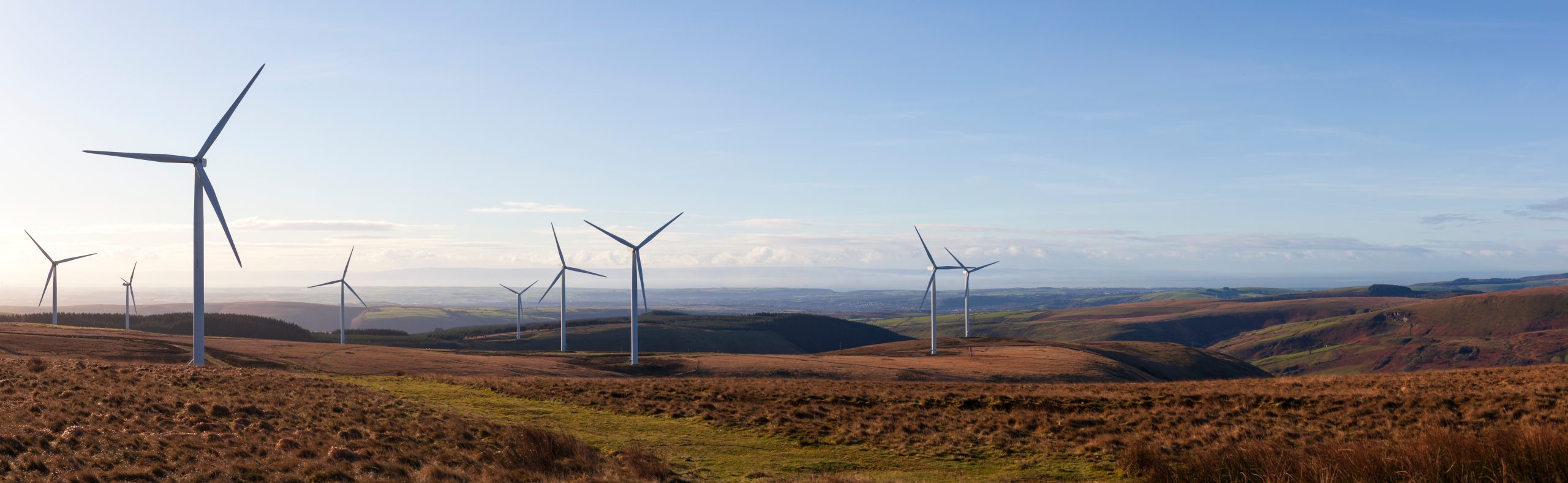
As a result, aluminium/copper compression cable lugs and connectors are also particularly suitable for use in offshore wind turbines. There is also the option to use tin plated aluminium cable lugs. This solution should only be used in spaces that are kept constantly dry, as even small amounts of damage to the tin layer are enough to start the contact corrosion process.
Al/Cu compression cable lugs
Compression cable lugs which are developed for the special connection of aluminium conductors and copper bars are made of electrolytic aluminium (E-Al). They feature an attached copper mounting bracket according to EN 13600.
Aluminium conductors at a glance
Pursuant to DIN 60228, four different types of aluminium conductors are available – some of which require special processing methods. The following conductor types are available:
single-stranded round conductors, class 1 (re)
single-stranded sector shaped conductors, class 1 (se)
multi-stranded round shaped conductors, class 2 (rm)
multi-stranded sector shaped conductors, class 2 (sm)
The abbreviations and other information can be found among the markings on the Al/Cu compression cable lugs. This will help you to determine which cable lug is best for which aluminium connector.
The markings »8 KL16 50 rm 70 se« mean
8:Metric bolt dimensions of the connecting bolt bore (in this case M8 bolt)
KL: Manufacturer code (Klauke in this particular instance)
16: Tool code
50 rm/sm: Nominal cross-section of the conductor in mm², when using a round or sector shaped multi-stranded conductor
70 re/se:Nominal cross-section of the conductor in mm², when using a round or sector shaped single-stranded conductor
For crimping Al/Cu compression cable lugs, we recommend using a hexagonal crimping die, according to DIN 48083 Part 4, or EKM60ID. Incidentally, Klauke aluminium inserts are silver, whereas copper inserts are gold/yellow. It is therefore very easy to tell them apart.
Al/Cu connectors: securely jointed Cables
Klauke offers reduction connectors to ensure that aluminium and copper are securely joined. Reduction connectors are often used in network repairs – more specifically in the production of non-tension connections for aluminium conductors in accordance with DIN EN 60228, and copper conductors in accordance with DIN EN 60228.
The connectors are made of two components: aluminium parts (E-Al) and copper parts (pursuant to EN 13600). The aluminium side generally has a larger diameter, because the lower conductivity is compensated by a correspondingly higher nominal cross-section.
As with compression cable lugs, the aluminium side of the connector also contains a compound, which is prevented from running out and drying out by a protective cap.
To ensure safe results when processing the Al/Cu compression joints, follow the relevant copper and aluminium processing specifications.
When using compression connectors underground, make sure that the joints are protected from moisture. It is best if you use a cast resin joint. The joint permanently protects the connections from moisture, dust and the penetration of foreign bodies.
Lastly, an important note on aluminium and copper cable lugs and compression joints. Do not expose these products to bending stress, otherwise there is a risk of breakage at the contact point between the two materials. Use in the overhead line sector is therefore not possible.
Crimping Cables, Lugs & Tools
Thorne & Derrick distribute Cable Lugs & Cable Connectors to terminate, splice and joint LV MV HV cables – this includes copper, aluminium and bi-metallic connectors and a range of crimping tools for specific use on all Low, Medium & High Voltage cable types.
Thorne & Derrick are Specialist Distributors to Solar EPC’s & High Voltage Jointing Contractors working on the design, construction and maintenance of UK, European and international projects supplying an extensive range of LV HV Solar Cables, Jointing, Substation & Electrical Eqpt.Based in the UK, we are highly customer responsive and absolutely committed to providing a world-class service.
We stock LV HV Solar Cables, Accessories & Electrical Equipment to enable the construction, maintenance and operation of utility-scale PV installations – our products connect 600V/1500V solar cables into combiner boxes, inverters, transformers and energise switchgear up to 33kV/132kV for high voltage grid connections.
Since 1985, we have provided expert technical support and express delivery from extensive UK stocks to world-wide destinations.
Thorne & Derrick | Distributed from Stock | Approved Supplier | UK & Export Sales
Klauke Cable lugs
The choice of cable lugs available for all kinds of applications in the electrical sector is huge.
Making the right choice can be harder than you might think. However, choosing the right lug is essential to ensuring a clean and secure crimping result.
This overview provides a more detailed insight into the most common lugs for copper conductors, helping explain to you what you need to look out for when making your choice so that your connection will indeed be secure and long-lasting.
Cable lugs for copper conductors, connected to the conductor by way of so-called cold forming, are some of the most common connectors in electrical engineering.
Choosing the right cable lug also depends on the conductor class to be processed. As an example, the following cable lug types are available for cables according to DIN EN 60228:
Class 1, 2, 5 and 6 conductors: compression cable lugs according to DIN 46235
Class 2 conductors: standard type tubular cable lugs
Class 2, 5 and 6 conductors: solderless terminals according to DIN 46234
To ensure safe crimping of conductors using DIN compression cable lugs, crimping tools with coded dies according to DIN 48083-4 are recommended in the standard. The requirements of the respective manufacturer must be observed for tubular cable lugs.
Solderless terminals according to DIN 46234 are processing using indent crimping.
Quality and resistance: on the test bench
Standards also apply to the electrical and mechanical properties of cable lugs. The international standard IEC 61238-1 part 1 applies in this particular instance. It specifies the tests that an electrical connection needs to fulfil in order to ensure long-term safe operation for its intended use.
The electrical connections must undergo different tests for this purpose. This involves an electrical durability test alongside a mechanical tension test. A test cycle simulates a practical application in this test.
Electricity is used to heat up the connection 1000 times to approx. 120 °C in order to bring about artificial ageing. The contact resistance is reviewed at regular intervals in between the tests.
Six high current tests are also carried out where the conductor is heated up to approx. 250°C in one second thanks to a short circuit. This high current test is required if the connector is due to be tested to check it is short-circuit protected.
The Klauke connecting material has also passed this test. The crimping connection passes the test if the contact resistance remained constant throughout.
Manufacturers are responsible for being able to guarantee the safety of their connections. With these additional tests that are carried out, you can rest assured that our connecting material satisfies the highest demands.
In addition, a significant amount of our materials are UL-tested and certified. This is particularly useful when control cabinets are to be supplied to North America, for example.
Electrical and mechanical properties of cable lugs
However, we also place additional requirements on the quality of our products that go beyond these standard requirements. Cable lugs made by Klauke are annealed as part of an additional manufacturing stage. This means we can reduce any hardening and tension in the material, as well as reduce the risk of breaking during crimping.
The quality of our cable lugs is already evident from their visual characteristics. Burr-free production and a consistently flat palm are signs of a high-quality product – likewise clean final machining of the tube section.
Contact our Sales Team for prices, technical support or to place an order for cable lugs or installation tooling for cutting and crimping cables manufactured by market-leader Klauke.
Klauke cable lugs and crimping tools are used by Jointers, Linemen, Panel Builders and Electrical Engineers to install underground cables and overhead line conductors on power, transmission and distribution networks including LV MV & HV systems, 11kV-33kV.
Crimping Cables, Lugs & Tools
Thorne & Derrick distribute Cable Lugs & Cable Connectors to terminate, splice and joint LV MV HV cables – this includes copper, aluminium and bi-metallic connectors and a range of crimping tools for specific use on all Low, Medium & High Voltage cable types.
Should you require technical assistance to select the correct cable crimping or cable cutting tools please contact us.
Thorne & Derrick are Specialist Distributors of cable tools to enable the preparation of all LV MV HV cables prior to the installation of Joints, Terminations & Connectors – this includes Klauke, Cembre, Alroc and Boddingtons cable jointing tools for removal of cable sheath, screen and insulation on 11/33kV (MV) and 66kV/132kV (HV) power cables.
This Case Study covers the problems caused by low oil level trips on aging transformers, the impact it has on downtime, availability and power generation. It goes on to discuss how Thorne & Derrick assisted Ventient Energy in custom designing and supplying a fit for purpose electrical heating solution to overcome the problem and effectively Winterise assets preventing downtime.
Who should read this? – Asset Managers in the onshore wind industry with responsibility for managing and maintaining oil filled transformers.
Causeymire – Ventient Energy
Thorne & Derrick have recently worked in partnership with Ventient Energy to provide a bespoke electrical heating solution for an onshore wind application. After a number of site meetings and application surveys with the client to understand the problem, T&D proposed a bespoke heating jacket solution to prevent downtime due to low temperatures.
Jon Priddy of Ventient Energy describes the problem
“For those of you managing assets with ageing oil filled transformers you may find this useful. If you do you’ll know that the tank expands and contracts with heat and cold. As they age the tank loses that capacity to contract and so now you have a bigger volume but the same amount of oil and usually a very finely tuned oil level sensor which as we know is a primary safety and protection feature.
Come the winter and those high pressure low wind speed days and bang, we have a trip. I have spent many a late night with the site team topping up, getting the contacts to close and getting everything back on. The result is downtime, a hit on availability and a hit on generation.
What’s the answer? A hugely costly campaign to change out all the transformers, a nearly as expensive retrofit of conservators (if you have the room and a good design), heating the transformer compartment in a large drafty steel tower fighting the physics of heat loss.
Obviously it doesn’t affect every site but typically anything over 15 years where the tank has lost that capacity to contract back to normal shape after the summer or high generation is a candidate.”
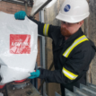
The nature of the problem included a number a variables and it was agreed that T&D would provide 5 trail heating jackets which would be put into use throughout the winter of 2022/23. The jackets were installed to the “top 5 offenders” during previous winters. The trials have proven successful and the client experienced no outages as a result of low oil trips during one of the harshest UK winters on recent record.
Pictured – fabricated model of the bottom of the transformer was made using the measurements taken from site survey. This meant the electrical heating jackets could be manufactured and test fitted prior to delivery.
The Solution for Oil Filled Transformers
Ventient approached Thorne and Derrick with a request for feasibility on applying a thermostatically controlled electric heating blanket to the base of the transformer with a view to stopping the oil from contracting to the point of a trip. This typically applies on high pressure (clear skies) low wind speed days and nights when there’s little in the way of current going through the transformer and temperatures drop to or minus zero.
Consideration had to be given to:-
Jacket Design – the client needed a solution which was simple and could be easily fitted, ideally as a single piece. The jacket also had to provide a very good fit as any additional heat losses may have negatively affected the overall performance. Representatives from T&D made the journey to Causeymire wind farm to carry out a site survey.
Power Supply – the power available was restricted due to only a single socket outlet being available.
Energy Efficiency – the design needed to be fit for purpose but using excessive power to solve the problem wasn’t an option.
Heat Loss – T&D have many years trace heating design experience and have carried out thousands of heat loss calculations for pipes, tanks and vessels. This was particularly challenging as we didn’t know the optimum oil temperature that would prevent it contracting enough to cause a trip. A safety factor had to be built into the design without using unnecessary power/energy.
Maintenance – any solution needed to be low/zero maintenance due to the remote location. The solution offered a fit and forget heating jacket. Once commissioned the jackets will operate using built in digital control thermostat. Any maintenance/inspections can be carried out alongside other routine maintenance.
Before & After Jacket Was Fitted to the Oil Filled Transformers
Heating Blanket For Oil Filled Transformer
Custom Heating Solution
Bespoke Heating Jacket
Client feedback
“The blankets were installed last year and wired up in November. A winter with some spectacularly low temperatures and some nights with low wind speeds has followed. And until 2 weeks ago, no low oil trips. This is the first winter in the last 6 where we haven’t had the problem.
Almost by way of verification the low oil trip 2 weeks ago occurred on one of the transformers without the blankets. The blankets are currently set to come on at 5°C ambient air temperature.
As usual with these things team work makes for the dream work. A huge shout out to Terry McDonald of Thorne & Derrick for crunching the numbers, doing the physics and coming up with a design, that was easy to fit and forget.
The great support and encouragement from the Ventient team, Alexa Belsham, Rui Meneses, who were willing to spend the cash and give it a try. For the support as ever from Tony Crombie who helped make the case and for Colin McIver of DWT for coming up with a power supply solution. A true “can do” team and collaboration.
So in short, it looks like we have a fix for this expensive (in every sense) issue with ageing oil filled transformers in colder climes.”
T&D have over 30 years process heating experience and are your pro-active problem solvers. If you are reading this and experiencing similar issues, please reach out to T&D and we will be happy to arrange an initial meeting to discuss your requirements.
Who are Ventient Energy?
Ventient Energy is a dynamic, pan-European renewable energy business and is one of the leading generators of renewable energy in Europe. They are Europe’s leading independent onshore wind group, with over 140 generating sites.
Thorne & Derrick distribute the most extensive range of MV HV Medium & High Voltage Cable Joints, Terminations & Connectors from manufacturers including 3M, Prysmian, Nexans Euromold, Pfisterer CONNEX & SEANEX and Shrink Polymer Systems.
Heat shrink, cold shrink, push-on and slip-over cable accessories enable the jointing, terminating and connection of 11kV-33kV and 66kV-132kV cables to oil, air or gas insulated switchgear, transformers, motors and overhead lines distributing electricity at medium/high voltages. Thorne & Derrick hold large stocks of 11kV 33kV 66kV Joints & Terminations suitable for XLPE, PILC and EPR cables, in both heat shrink and Cold Shrink technologies, to service the medium/high voltage power cable accessory requirements of UK and international customers.
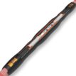
Nexans 400AR-4BC HV Bushings
Thorne & Derrick, UK Distributor for Nexans Power Cable Accessories, are pleased to announce the release of the new EUROMOLD® Interface C in-air bushing 400AR-4BC, up to 24kV – 1250 A. The new Interface C in-air bushing 400AR-BC will replace the Interface D in-air bushing 672TBC, for use in medium voltage electrical equipment insulated with air in hazardous area locations according to the ATEX Directive.
The in-air MV equipment bushing is used in industrial applications such as the manufacture of motors, pumps and locomotives – the bushing is ATEX Certified for use in Potentially Explosive Atmospheres according to the following classification:
II 2 G
Ex eb IIC Gb
Ts= -20°C to 95°C
Thorne & Derrick distribute the most extensive range of MV HV Medium & High Voltage Cable Joints, Terminations & Connectors from Nexans Euromold to connect, splice, repair and maintain medium/high voltage cable and power distribution systems
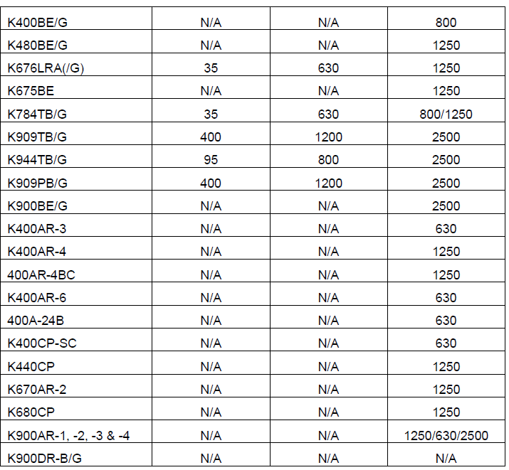
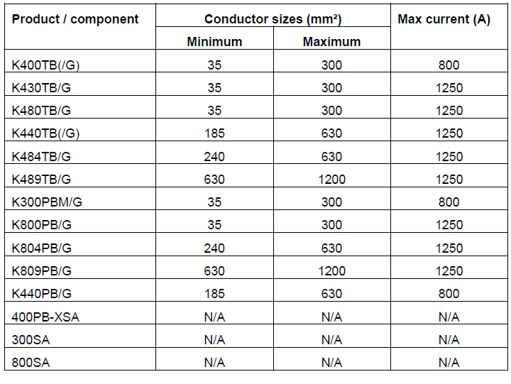
The correct selection and specification of Nexans Euromold connectors is dependent on the cable specification and the electrical equipment MV HV bushing type. There are 6 bushing interfaces common to MV electrical equipment (A, B, C, D, E or F).
Nexans 400AR-4BC In-Air Bushing
400AR-4BC Advantages
On the new Interface C in-air bushing you can install all separable connectors of the Interface C product family. It also offers the possibility to install a Surge Arrester.
The new Interface C in-air bushing is also available with ATEX/IECEx/UKEx certification.
Part Number
703937 – K400AR-4BC/J + KBC-RING CLAMP 3 *SS
703939 – K400AR-4BC/J-ATEX-IECEx + KBC-RING CLAMP 3 *SS
The bolted type equipment bushings 400AR-4BC are moulded epoxy insulated parts and meet the requirements of CENELEC EN 50180. A non-tracking insulating rubber boot is installed over the bushing shank.
Specification | Construction & Electrical Characteristics
T&D Win Excellence in Customer Service Award At HazardEx 2021| Read Press Release
Thorne & Derrick International, based in the UK, were voted Winners of the Award for ‘Best Customer Service’ at the HazardEx Gala Dinner in 2021. The competitive Award category at the prestigious event was for providing excellent customer service over previous 2 years.
Thorne & Derrick are leaders in the development and distribution of Product Innovations that deliver significant improvements to clients plant, people and operational safety in the explosive atmosphere industries. Your proactive problem solvers experienced in succession planning for the replacement of obsolete, non-conformant and legacy equipment in hazardous areas. Your first-choice provider of innovative and competitive solutions to ensure ATEX & IECEx ComplianceforLow & Medium Voltage Cables & Hazardous Area Electrical Equipment to UK and international projects.
THORNE & DERRICK
SPECIALIST ELECTRICAL DISTRIBUTOR
Thorne & Derrick supply LV HV Cable Accessories, Installation & Electrical Equipment – we can assist with the Competitive Supply & Technical Specification of joints, terminations, connectors and preparation tools for the energisation of all types of air or gas insulated electrical equipment from stock up to 66kV.
MV HV – Medium & High Voltage Cable Joints, Terminations & Connectors (11kV 33kV EHV)
Electrical Safety
Solar Farms
Guest Article By Paul Hopton Deputy Managing Director at Electrical Safety UK Limited
Thorne & Derrick distribute electrical safety equipment to substation engineers, cable jointers, overhead linesmen and utility workers – this includes insulating gloves, voltage detectors, insulating mattingand portable earthing to ensure worker safety when carrying out maintenance on LV-HV switchgear, substations, cables and electrical equipment in the solar industry.
Electrical Safety UK have helped many companies in different industries in a number of locations around the World to improve their electrical safety management systems.
In this Article we are going to focus on Solar Farms and discuss whether there any hazards that may be specific to that industry.
We recently carried out an electrical safety audit in the Middle East at one of the largest solar farms in the world. The brief was to carry out an audit of their current operations and safety management system to identify if any improvements could be made.
We started by interviewing Electrical Managers, Supervisors and Tradesmen to ascertain where they had good practice and where improvements could be made. The scope of these interviews covered but was not limited to:
Electrical Accident Investigation and Root Cause Analysis
Software and Device Parameter Backups
Reliability and Bad Actors
Safe Systems of Work including Switching Programs and Earthing Diagrams
We also carried out site surveys and asked personnel who were working on site about electrical safety and the management of electrical risks.
Results
We identified several areas where there were opportunities to improve. These were presented to the site management team in a feedback presentation and more formally in a report. The findings showed significant opportunities in Arc Flash Risk Management, Isolations and Electrical Shock Risk Management.
Hazards specific to Solar Farms
The main issue specific to Solar Farms that we identified was with the Solar Panels themselves as they generate electricity. The good news is that Solar Farms are modular and so it is easier to produce isolation and safe working procedures, than for more typical industrial or commercial electrical distribution systems.
“Test before touch” or “Test for dead” processes are very important. You should ensure that the correct type of test equipment is used. Voltage indicators should be tested immediately before and after use with a proprietary proving unit.
There are also a lot of power inverters and other enclosures out in the field that should be shrouded to IP2X to minimise electric shock risk during fault finding activities. As the Solar Farm gets older, it is important to make sure that the IP2X protection is maintained by auditing and inspection especially during and after maintenance activities.
Electrical Safety Management Systems
I think it is fair to say that Solar Farms have not been around as long as many industrial and commercial electrical networks and can be operated by organisations that do not have a long history of electrical safety management experience. This lack of experience can lead to gaps in their Electrical Safety Management Systems.
Unfortunately, failures of an Electrical Safety Management System can result in serious injury or fatality. Fortunately, these events are rare but because of the complacency that can result from their scarcity, when the holes in the Swiss cheese line up, the worst can happen.
Far better to have someone independent to the Organisation to audit your Electrical Safety Management System to prevent the accident before it happens.
Solar Farms can sometimes be operated and maintained by the Company that designed and installed them rather than the owner. Dependent upon the Company supplying the Solar Farm, they may or may not have a great deal of operational and electrical safety management experience. If they do lack experience, they might be more likely to have an electrical accident.
The Company owning the asset (Electrical Duty Holder) might not take kindly to the exposure to public/regulatory scrutiny that this would bring.
Calculating the arc flash hazard for each of piece of equipment on a Solar Farm should cost significantly less that carrying out an arc flash study on a typical industrial or commercial electrical distribution system.
The reason for this is that Solar Farms tend to be very modular in their construction. Therefore detailed modelling of one of the modules can be quickly and cheaply replicated many times for the rest of the network.
This obviously reduces the overall cost of the arc flash study for a Solar Farm versus other types of electrical networks.
About Electrical Safety UK
Electrical Safety Management is our core business. We provide expert consultancy and advice services for blue chip organisations across Europe concerned with the safe management of risk associated with all electrical work activities.
Electrical Safety UK provide a multi-faceted holistic approach including a full electrical safety management programme, project management and policy documentation all bespoke to the client’s requirements including fully accredited and bespoke training courses and personnel assessment programmes.
2 Genesis Business Park
Sheffield Road
Rotherham
S60 1DX
Tel: 0800 652 1124
Tel: 01709 961 666
Thorne & Derrick are Specialist Distributors to Solar EPC’s & High Voltage Jointing Contractors working on the design, construction and maintenance of UK, European and international projects supplying an extensive range of LV HV Solar Cables, Jointing, Substation & Electrical Eqpt. Based in the UK, we are highly customer responsive and absolutely committed to providing a world-class service.
We stock LV HV Solar Cables, Accessories & Electrical Equipmentto enable the construction, maintenance and operation of utility-scale PV installations – our products connect600V/1500V solar cables into combiner boxes, inverters, transformers and energise switchgear up to 33kV/132kV for high voltage grid connections.
Since 1985, we have provided expert technical support and express delivery from extensive UK stocks to world-wide destinations.
Compound Box Filling Compound end boxes rarely get attention — until one fails. Across ageing networks, replacement of compound-filled end boxes is becoming more frequent, particularly where original insulation systems have deteriorated and air insulation is not practical because...
Nexans 240–300mm² Multi-Joint – Medium Voltage Cable Joint Installation Medium voltage cable jointing requires reliability, consistency and safe installation practices. The Nexans 240–300mm² Multi-Joint is designed to simplify medium voltage jointing while maintaining high electrical performance for demanding power...


")


")