

Blog
MV HV Cable Laying, Installation & Support Products | Offshore Windfarms
January 22nd, 2020
MV HV Cable Laying, Installation & Support Products | Offshore Windfarms
Cable Laying, Installation
& Support Products
Courtesy Slingco – Manufacturer of Cable Pulling & Support Products
Uploaded by Chris Dodds | Thorne & Derrick Sales & Marketing Manager
Slingco has developed a range of cable socks and cable grips tailored for the support and installation of LV MV HV cables in the renewable energy sector:
- Cable installation – offshore and onshore
- Cable support inside wind turbines
- Cable management
WIND TURBINE CABLE SUPPORT socks
These cable socks incorporate special features for wind turbines. With rounded copper ferrules, the cable pulling socks offer reduced cable contact for high vibration environments while still allowing excellent working loads and LV MV HV cable support.
MARINE CABLE Grips
Galvanised steel type cable grips are extremely heavy duty and suitable for large diameter underwater cable installation. Available in single eye, double eye lace closing and double eye, sizes range from 4 inches to over 20 inches. Special application cable socks are manufactured to order.
Option 1 – Limited Lay Down
Galvanised cable grips with aluminium ferrules are suitable for cable installation / loading and typically used for OSS pull in.
Option 2 – Limited Lay Down / Wet Storage
Galvanised grips with galvanised steel ferrules for installation / loading with limited wet storage that can be further extended for longer wet storage with the addition of an anode.
Option 3 – Lay Down / Wet Storage up to 1000 Hours
Stainless steel cable grips with stainless steel ferrules for laying and limited wet storage up to <1000 hours, subject to inspection after such time elapsed.
Option 4 – Lay Down / Wet Storage over 1000 Hours
Non-metallic grips in Aramid for used for cable laying and wet storage applications over >1000 hours, these would be the preference of the leading installation contractors based in the Netherlands and Europe, degradation was not seen other than some signs of salt on the surface. Non-metallic cable grips are specified to provide safe cable handling and are used for offshore saltwater environments when prolonged lay down durations are required.
LACE-UP CABLE socks
Mainly used where a ‘typical’ cable sock cannot be fitted over a connector at the end of a cable, ‘L-type’ cable socks are used in cable pulling when the end is not accessible. The mesh is wrapped around the cable, then closed with the wire lace provided.

MV HV Windfarm

3M Nexans Euromold Pfisterer Stockists | Joints Terminations Connectors up to 66kV

Press Release | Thorne & Derrick Appointed Approved Stockist for UK Leading Cable Pulling Equipment Manufacturer
CABLE SOCKS & PULLING PRODUCTS LV MV HV
Complete range of LV, MV and HV cable pulling products for installation and enabling cable jointing in trench or ducts including LV, 11kV/33kV medium voltage (MV), 66kV/132kV high voltage (HV) and EHV transmission and distribution cables up to 400kV.
➡ See Also Cable Laying, Installation & Support Products | Offshore Oil & Gas Cables

Cable Rollers | Duct Rods | Cable Socks | Cable Lubricant | Duct Seals | Cable Duct
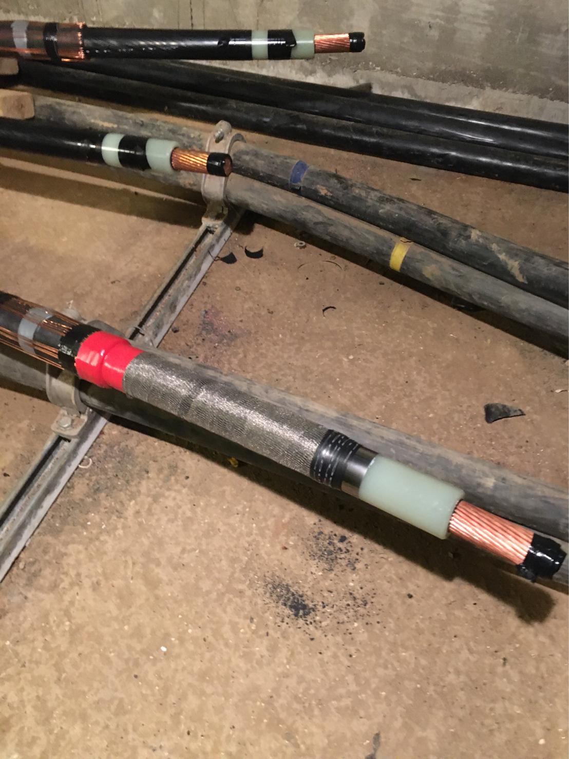
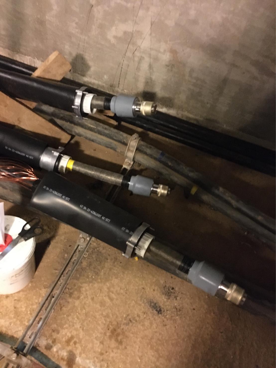
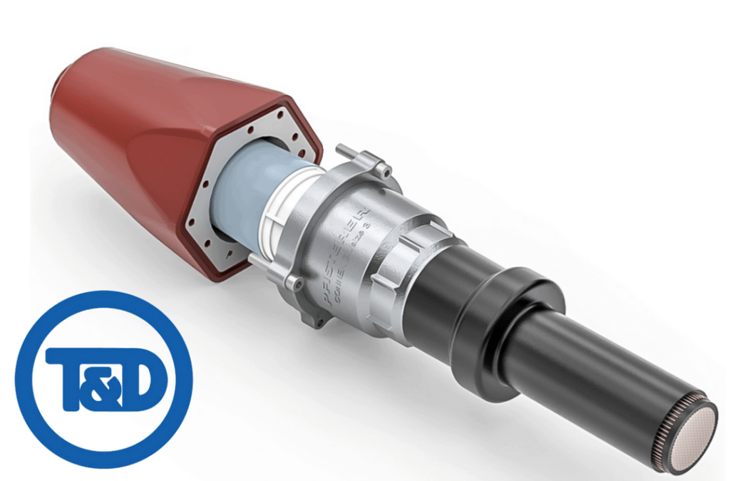
Pfisterer 3XL Cable Terminations | Cables Stripped & Pluggable
January 22nd, 20203XL
Pictured : 6 x 630sqmm 33kV 3XL Pfisterer Cable Terminations.
Image Courtesy : Lee Richards (Self Employed Cable Jointer at LR Power Services).
T&D are Main Distributors & Stockists for the Pfisterer range of Medium Voltage Power Products including Connex Plugs, Cable Jointing Tools, Sicon Connectors, Surge Arresters and Electrical Safety Equipment.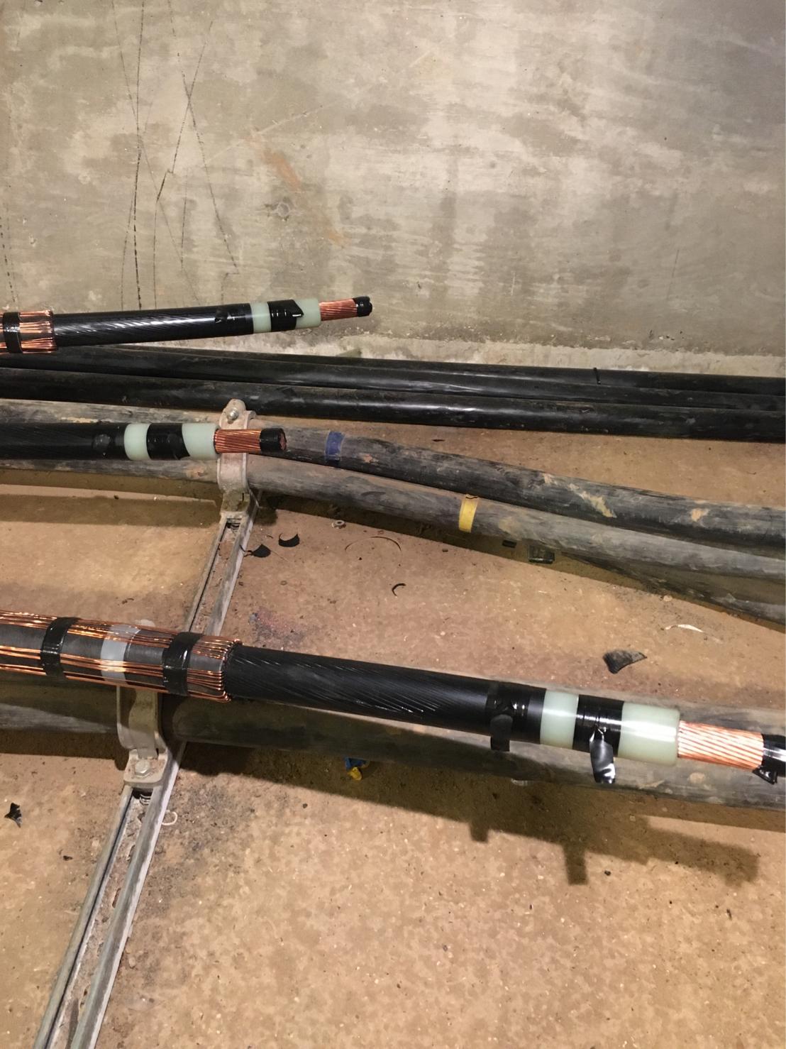


further reading
More Jointing work from Lee Richards ➡
- LV Cable Diversion 4 Core PILC to 4 Core Wavecon Straight Joint
- PILC Cable Joints & LV Switchgear Connections
MV Connex Training with Pfisterer
pfisterer training courses
CABLE JOINTER TRAINING FOR MV HV CONNEX CONNECTORS
PFISTERER have announced the launch and opening of their Medium Voltage CONNEX Training Courses covering CONNEX Size 1 to 3-S-XL products up to 52kV – the training courses are being conducted from their new purpose built training facility in the UK.
Safety and reliability are essential factors in medium voltage power system applications placing particular demands on assembly and installation skills of the cable jointer.
It is therefore imperative that all medium / high voltage cable jointers who work with CONNEX products are trained and certified by PFISTERER.
You can contact Thorne & Derrick to arrange your PFISTERER training course today.
![]()
Jointers blog
Subscribe now to our POWER NEWSLETTER– a monthly email circulation packed with news, projects, videos, technical tips, training information, promotions, webinars, career opportunities and white papers.
Includes access to our popular JOINTERS BLOG with contributions from utility professionals, linesmen and cable jointers working on MV HV EHV cables and overhead lines typically at 11kV, 33kV, 66kV and up to 132kV.
15,000+ Subscribers. ➡ 
Installation of Rail Foot Cables
January 20th, 2020
Installation of rail foot cables
Installation
Lay the cable down outside the area of the tracks and align it.
When doing so the cable must not be unwound over the flange of the delivery drum. In that case loops will occur which cannot be compensated during the lay. Lay the cable along the external side of the rail foot. When installing the cable, ensure that there is a reserve length of approximately 5 metre on each side.
If local conditions are met, the cable may also be laid directly along the external side of the rail foot from a slow moving railcar. Installation of the rail foot cable and fastening to the rail foot should take place from one end only or from the middle towards both ends. If installation is attempted from both ends, loops will occur in the cable. In this case damage to the cable by passing trains could not be ruled out.
At earthings, points, track magnets, level-crossings or in the case of a necessary joint the rail foot cable should be led away from the track with the help of a rail foot junction authorised and released by the rail operator. The cable should then be laid in the ground or in cable troughs, or at least be placed inside a protective pipe. For this procedure the minimum bending radius of the cable, as stipulated by the manufacturer, must be observed.
The placing of cable joints directly at the rail foot is not permitted.
Instead the cable ends to be joined must be led away from the rail foot and brought together in a sleeve next to the tracks.
Ideal installation of rail foot cables

Inadequate installation creates loops
Fastening Cables
The cable may only be fastened with rail foot clamps which are approved for the particular type of track, since the permissible downward pressure is dependent on the type of cable and the track shape.
We recommend allowing one rail foot clamp in at least every second sleeper spacing and never fitting more than one single cable under the rail foot clamps at the rail foot.
In principle the installation of two rail foot cables under one rail foot clamp is possible. Special attention need to be paid to the diameter of the cable and the guidelines of the manufacturer of rail foot clamps. A combination of very small with larger rail foot cables shall be avoided as the expansion of both cables due to temperature changes are different and will result in loops. Furthermore the smaller cable shall always be installed on top.

Inadequate installation creates loops of the lower cable

Installation of Rail Foot Cables
Further Reading
- Cable Laying | The Importance of Cable Installation Instructions
- Cable Drums | Recommended Transport & Storage
- How to Prepare Cables To Avoid Cable Damages & Faults
- Cable Pulling | Safe Pulling of Cables Using Motorised Pullers
- Cable Pulling | Safe Pulling of Cables Using Manual Laying
- Installation of Cable Sleeves | Jointing & Splicing Cables

Cable Pulling Equipment
Thorne & Derrick distribute an extensive range of Cable Pulling & Laying Equipment to enable the safe installation of fibre and copper cables within the telecommunications industry. Safely installed cables reduces operational and maintenance requirements to the network and reduced service interruption to telecom cables, wires, ducts, cabinets and exchanges – products include cable spiking tools, conduit rods, cable lubricant, cable socks and rollers.

Installation of Cable Sleeves | Jointing & Splicing Cables
January 17th, 2020
Installation of Cable Sleeves
The pulled in cables are not always long enough to join together two connection points without interruption. Sometimes the position and type of laying run require the use of separate lengths of cable.
For reasons of cost and space there-fore the simple lengthening of a cable is usually achieved with cable sleeves. Junctions from the cable or division of a cable into several continuing cables must be carried out with suitable distributing boxes. The connection of two or more cables within boxes or cable sleeves must be undertaken with the greatest care and be protected from dampness or moisture.
A tent must be erected for the duration of the installation. Work on the sleeve and box should be undertaken quickly and without interruption.
On the below Draka provide a verbal and pictorial description of the procedure for installing a sleeve. Please note in every case the parameters of the sleeve manufacturer, the information sheets of the cable manufacturer, as well as the safety regulations of the network operator.
LV MV HV Cable Preparation
Preparation begins with the choice of the correct sleeve for the corresponding cable.
For our example we have chosen a signal cable with reduction factor of the type Draka SIGDRAK® AJ-2Y(L)2YDB2Y 3x4x1.4 (H45) rk-group 500 as well as the matching connecting heat-shrinkable sleeve and protective heat-shrinkable sleeve.
Although Draka carried out the installation indoors, the same procedure applies outdoors: both cable ends must be fixed to cable stands or similar devices in such a way that the work environment is clean, tidy and protected from moisture. The cable ends should generously overlap the external edge of the sleeve.
➡ Recommendation: feel free to allow a little extra here.
Removal of the Cable Sheath
Removal of the outermost protective cable sheath must take place according to the instructions of the sleeve manufacturer.

Removal of the cable sheath
Removal of the Armouring
Removal of the armouring (steel band) occurs according to the stipulation of the sleeve manufacturer. When sawing into the steel band the shielding wires lying beneath must not be damaged. For thick cables and thick steel bands it is possible to use an iron saw with a depth marker. In our case a simple small hacksaw also served the purpose.

Removal of the armouring
The upper layer of steel band is sawn into and can now be carefully unwound using a pair of pliers. Please take care with sharp edges and points: danger of injury!
The same procedure is followed with the second layer of steel band. Please pay careful attention here in particular to the intactness of the shielding wires which lie beneath.
The opposite cable end is to be prepared as appropriate.

The opposite cable end is to be prepared as appropriate
The shielding wires are also shortened according to instructions. Then there are two possibilities: armouring and shielding wires can now be connected immediately or, as in our example, at the end after the connecting heat-shrinkable sleeve has been installed.

The shielding wires are also shortened according to instructions

Cutting shielding wires
Making Contact with the Laminated Sheath
The inner laminated sheath is carefully stripped to the prescribed length. Damage to the core layers below can reliably be avoided by using a special stripping tool.

Making contact with the laminated sheath
An incision is made in the remaining laminated sheath in two places at a maximum distance of 15 mm apart, each cut being 30mm long. The resulting folds in the sheath are carefully bent upwards .In the picture on the right the laminated sheath, drain wire and plastic film are fixed with some plastic tape.

An incision is made in the remaining laminated sheath
The V-clip of the shield continuity wire is laid sideways around the edge of the cut fold of cable and closed tightly with combination pliers. In this way the teeth on the clip cut through the cable sheath into the aluminium band. A secure contact is thus guaranteed.

V-clip of the shield continuity wire is laid sideways around the edge of the cut fold of cable
Then the V-clip and laminated sheath are wrapped with three layers of plastic tape. The drain wire can be cut off or additionally wrapped around the clip. If necessary please note any supplied customer instructions for this.
Once the cores have been spliced, the shield continuity wire is lined up, without the spare loop, straight along the splice, where it is connected as appropriate with the laminated sheath of the second cable.

Once the cores have been spliced, the shield continuity wire is lined up
Splicing the Cores
When splicing the copper cores the correct stranding order must be observed. In our case the tracer quad is suitably clearly marked by knotting the thin blue plastic tape.

Splicing the cores
The cores are individually stripped of insulation with the help of a suitable cable stripper. Please take care that the copper conductors do not become soiled or damaged or exposed to dampness or moisture.

Cores are individually stripped of insulation
Both stripped core ends are connected with a crimp splice and joined together with a pincer to be tension-proof. Please be absolutely certain to follow the correct coding and sequence of the cores and quads to be connected. Errors are usually not discovered until the final check or first operation and lead to costly correction measures.

Both stripped core ends are connected with a crimp splice
After installation the crimp splices are carefully shrunk with a burner. Released glue and the closely fitting plastic protect the bare copper joint mechanically and against dampness.

After installation the crimp splices are carefully shrunk with a burner
This is what the splices look like following successful shrinkage. When a connection has been shrunk correctly, some glue will seep out at the sides.

This is what the splices look like following successful shrinkage
Staggered splices result in a narrow joint. If you have not already done so, you should now connect the shield continuity wire with the laminated sheath of the opposite cable.

Staggered splices result in a narrow joint
Preparation of the Inner Connecting Heat-shrinkable Sleeve
The two laminated sheaths facing the core splices are now cleaned with a cleansing cloth so that a 150 mm wide area is oil-free.

Preparation of the inner connecting heat-shrinkable sleeve
Once the oil has been removed the laminated sheath is roughened across the cable axis with an emery cloth. Any pitted areas in the sheath must also be roughened.

Laminated sheath is roughened across the cable axis with an emery cloth
Following this the cleaned and roughened areas are heated with a burner until they are hand-hot.

Following this the cleaned and roughened areas are heated with a burner until they are hand-hot
Before installation of the actual heat-shrinkable sleeve, the drying agents supplied with the packaging should be fixed around the core splice with adhesive tape.Please do not wrap the entire drying agent with isolating tape as this will prevent it from fulfilling its function. Simple wrapping to keep the agent in place is sufficient.

Before installation of the actual heat-shrinkable sleeve, the drying agents supplied with the packaging should be fixed around the core splice with adhesive tape.
The protective padding should be rolled together before the installation (pre-formed) and then laid as tightly as possible overlapping the core splice and secured with adhesive tape.

The connecting heat-shrinkable sleeve
The lamellar areas of the protective padding should be unwound with adhesive tape.

The lamellar areas of the protective padding should be unwound with adhesive tape
Line up centrally the seal for the heat-shrinkable sleeve. It must extend beyond the protective padding by the same length on each side.It is helpful to mark at least on one side of the laminated sheath how far the seal will extend.

Line up centrally the seal for the heat-shrinkable sleeve

The seal is laid completely around the splice and the sealing edge pulled up.
When shrinking the sleeve, begin in the middle. For this procedure heat the complete area of the sleeve and shrink it towards one end. Then work on the other end. Move the flame back and forth evenly and continuously to avoid localised burning.

When shrinking the sleeve, begin in the middle
The shrinking process is over when the seal has evenly shrunk, the green colour pigment in the sleeve material has disappeared and the white indicator line is easily visible under the sealing edge. At the ends small amounts of glue must be seeping out of the cable.
Caution: the shrunken seal and the sealing edge retain the heat for a very long time (danger of burns!). As it cools the sleeve shrinks a little further.

The shrinking process is over when the seal has evenly shrunk
Connecting the Cable Armouring
Before connecting the armouring and the shielding wires, the exposed areas of the latter should be cleaned metallically bright and roughened. When doing this, please also heed the armouring layer beneath.

Connecting the armouring
The copper fabric tape should be wound according to instructions in a single layer around the armouring and shielding wires. The remaining fabric tape should be cut off and retained.

The copper fabric tape should be wound according to instructions
The supplied contact plates are pre-formed according to instructions, laid around the copper fabric tape and wrapped and secured with one layer of the copper fabric tape (with a max. 5 mm overlap).

The supplied contact plates are pre-formed according to instructions
The earth wire is cut to 1.5 times the length of the removed section of the outer protective coating, and pulled over the neighbouring protective tube in such a way that approximately 100 mm are left bare and free at both ends of the earth strand. The end of the earth strand is fanned out and, flush with the removed edge of the armouring, laid flat onto the copper fabric tape and secured close to the end of the removed edge with a roll spring. The earth wire is fixed with the second roll spring with three layers, then pulled back and secured with the remaining layers of the roll spring.

The earth wire is cut to 1.5 times the length of the removed section of the outer protective coating
At the end of installation the earth wire looks like this. The second side should be dealt with in the same way.

At the end of installation the earth wire looks like this
Installation of the Protective Wrap
Before the protective wrap is fitted the external protective coating must be cleaned, roughened and warmed. The whole contact area is preheated using heat shrink gas torch, before the shrink tape (protective wrap), starting with the PE-sheath between the inner sleeve and roll spring, is tightly wrapped half-overlapping the whole contact area up to the outer sheath. The area where the earth wire protrudes is excluded as little as possible. A maximum of half the width of shrink tape should be placed on the protective coating.

Installation of the protective wrap
The protective wrap is heated with a low flame until the tape shrinks and glue seeps out at the overlaps.

The protective wrap is heated with a low flame until the tape shrinks and glue seeps out at the overlaps
The shrunken tape and the seeping glue should be clearly visible.

The shrunken tape and the seeping glue should be clearly visible
Installation of the Protective Heat-shrinkable Sleeve
The earth wire is laid radially around the splice and secured with some plastic tape. Then the metal protective padding should be tightly laid around the inner sleeve, centrally and overlapping, and secured with adhesive tape. The conical ends should be carefully wrapped with plastic adhesive tape.

Installation of the protective heat-shrinkable sleeve
The outer sheath is cleaned until it is oil-free, roughened across the cable axis and then heated with a low flame to hand-hot temperature.

The outer sheath is cleaned until it is oil-free, roughened across the cable axis and then heated with a low flame to hand-hot temperature
The wrapping on the conical ends of the metal protective padding should be clearly visible.
The seal for the heat-shrinkable sleeve is laid centrally over the connecting point and the projection marked on at least one side of the laminated sheath.

The wrapping on the conical ends of the metal protective padding should be clearly visible
The flame-retardant foil (self-adhesive aluminium foil) is attached so that it is laid over the marked line approximately 10 mm towards the inner sleeve. In this way it reaches a maximum of 10 mm into the sleeve, whilst the greater part of the foil remains outside the heat-shrinkable sleeve. The foil should be smoothed over with a blunt tool, for example the smooth handle of a pair of pliers or the handle of a hammer.

The flame-retardant foil (self-adhesive aluminium foil) is attached so that it is laid over the marked line approximately 10 mm towards the inner sleeve
The heat-shrinkable sleeve is placed centrally around the metal protective padding and closed on both sides with the sealing edges. The connection clip is placed between both ends of the sealing edges in the centre of the sleeve.

The heat-shrinkable sleeve is placed centrally around the metal protective padding and closed on both sides with the sealing edges
Before shrinkage the sleeve should be centred. The two flame-retardant foils which reach slightly into the sleeve on both sides may serve as orientation.

Before shrinkage the sleeve should be centred
When shrinking the sleeve, begin in the middle. For this procedure heat the complete area of the sleeve and shrink it towards one end. Then work on the other end. Move the flame back and forth evenly and continuously to avoid localised burning. Heat the shrink seal until the green dots on the seal have turned black.

When shrinking the sleeve, begin in the middle
It should be easy to recognise that the green dots on the seal have almost completely disappeared. Glue will leach slightly out of the sleeve end lying on the flame-retardant foil. The white indicator line under the sealing edge is clearly visible. The protective heat-shrinkable sleeve is correctly closed and is water-tight. As it cools it will shrink a little further.
It should be easy to recognise that the green dots on the seal have almost completely disappeared
Further Reading
- Cable Laying | The Importance of Cable Installation Instructions
- Cable Drums | Recommended Transport & Storage
- How to Prepare Cables To Avoid Cable Damages & Faults
- Cable Pulling | Safe Pulling of Cables Using Motorised Pullers
- Cable Pulling | Safe Pulling of Cables Using Manual Laying
- Installation of Rail Foot Cables
Cable Pulling Equipment
Thorne & Derrick distribute an extensive range of Cable Pulling & Laying Equipment to enable the safe installation of fibre and copper cables within the telecommunications industry. Safely installed cables reduces operational and maintenance requirements to the network and reduced service interruption to telecom cables, wires, ducts, cabinets and exchanges – products include cable spiking tools, conduit rods, cable lubricant, cable socks and rollers.
Cable Pulling | Safe Pulling of Cables Using Manual Laying
January 17th, 2020
Cable Pulling | Safe Pulling of Cables Using Manual Laying
Manual Laying
For manual pulling in of the cable one thing that must be ensured is that the cable is on no account pulled over the flange of the cable drum.
If the cable needs to be pulled in in sections, due to local conditions, no rings (image 1) may be laid, since this means that the cable is inappropriately twisted by 90°. Combined with high forces of tension and various deflections this can lead to destruction of the protective coating (image 2).
The formation of loops can easily be seen in the above pictures. In narrow cable shafts and when being pulled the cables are exposed to considerable torsion, which can lead to severe damage of the cable (image 1 on left).
If the cable is to be laid out in sections this may only occur in so-called ‘figures of eight’ (image 2 on the right), which are set out according to the cable diameter (note the bending radius!). Torsion of the cable can then no longer occur.

Image 1 – Safe Pulling of Cables Using Manual Laying

Image 2 – Destruction of the protective coating
Press Release | Thorne & Derrick Appointed Approved Stockist for UK Leading Cable Pulling Equipment Manufacturer
Further Reading
- Cable Laying | The Importance of Cable Installation Instructions
- Cable Drums | Recommended Transport & Storage
- How to Prepare Cables To Avoid Cable Damages & Faults
- Cable Pulling | Safe Pulling of Cables Using Motorised Pullers
- Installation of Cable Sleeves | Jointing & Splicing Cables
- Installation of Rail Foot Cables
Cable Pulling Equipment
Thorne & Derrick distribute an extensive range of Cable Pulling & Laying Equipment to enable the safe installation of fibre and copper cables within the telecommunications industry. Safely installed cables reduces operational and maintenance requirements to the network and reduced service interruption to telecom cables, wires, ducts, cabinets and exchanges – products include cable spiking tools, conduit rods, cable lubricant, cable socks and rollers.
